torque HONDA CR-V 2000 RD1-RD3 / 1.G Owner's Manual
[x] Cancel search | Manufacturer: HONDA, Model Year: 2000, Model line: CR-V, Model: HONDA CR-V 2000 RD1-RD3 / 1.GPages: 1395, PDF Size: 35.62 MB
Page 176 of 1395
Oil Filter
Replacement (cont'd)
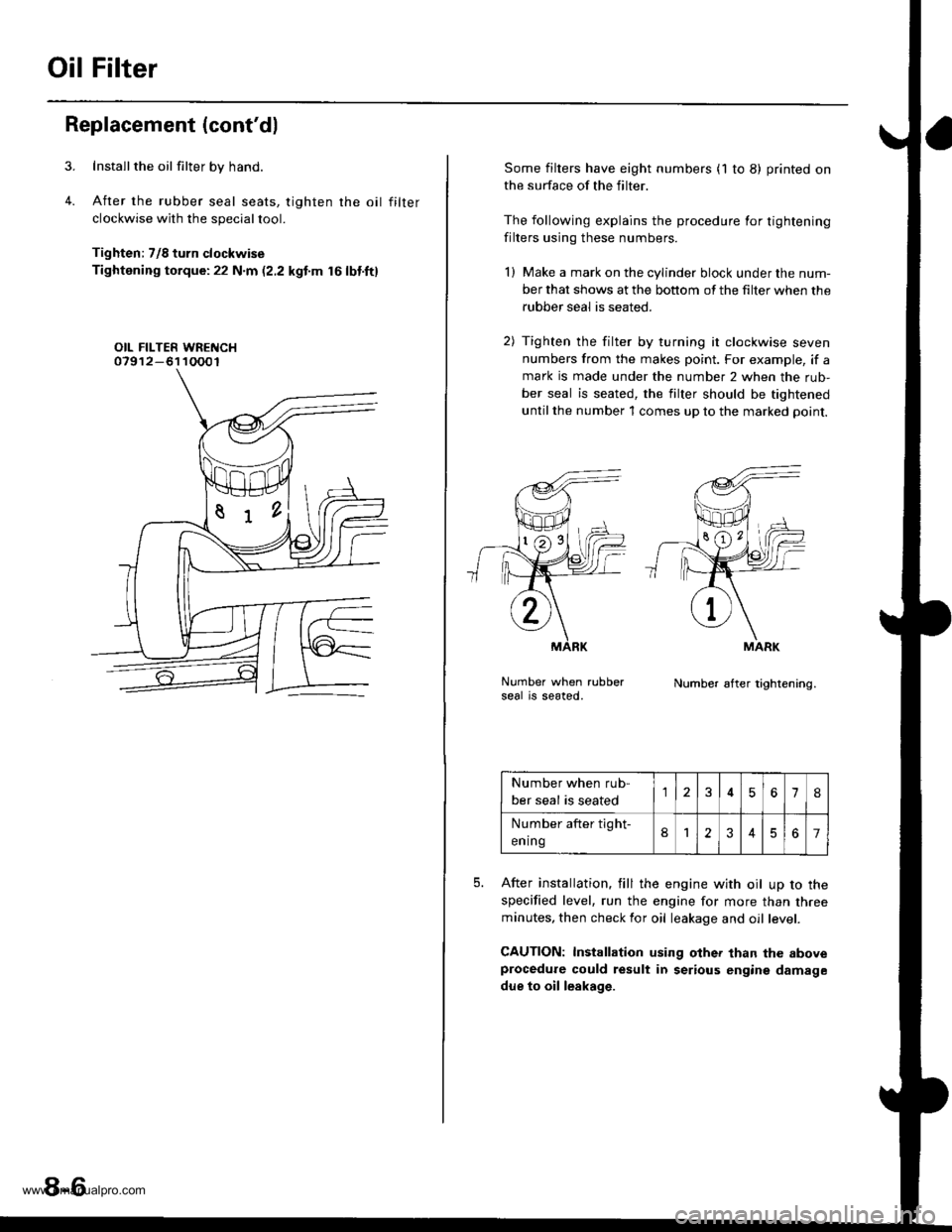
Installthe oil filter by hand.
After the rubber seal seats, tighten rhe oil filter
clockwise with the special tool.
Tighten: 7/8 turn clockwise
Tightening torque:22 N.m (2.2 kgt'm 16lbt.ft)
OIL FILTER WRENCH07912-61 10001
8-6
Some filters have eight numbers (1 to 8) printed on
the surface of the filter.
The following explains the procedure for tightening
filters using these numbers.
l) Make a mark on the cylinder block under the num-
ber that shows at the bottom of the filter when the
rubber seal is seated.
2) Tighten the filter by turning it clockwise seven
numbers from the makes point. For example, if a
mark is made under the number 2 when the rub-
ber seal is seated, the filter should be tightened
until the number 1 comes up to the marked point.
Number when rubberseal is seated.Number af ter tightening.
5.After installation. fill the engine with oil up to the
specified level, run the engine for more than threeminutes, then check for oil leakage and oil level.
GAUTION: Installation using other than the aboveprocedure could result in serious engine damage
due to oil leakage.
MARK
Number when rub-
ber seal is seated567IJ
Number after tight-
ening8123467
www.emanualpro.com
Page 332 of 1395
PGM-FI System
Knock Sensor {KSl
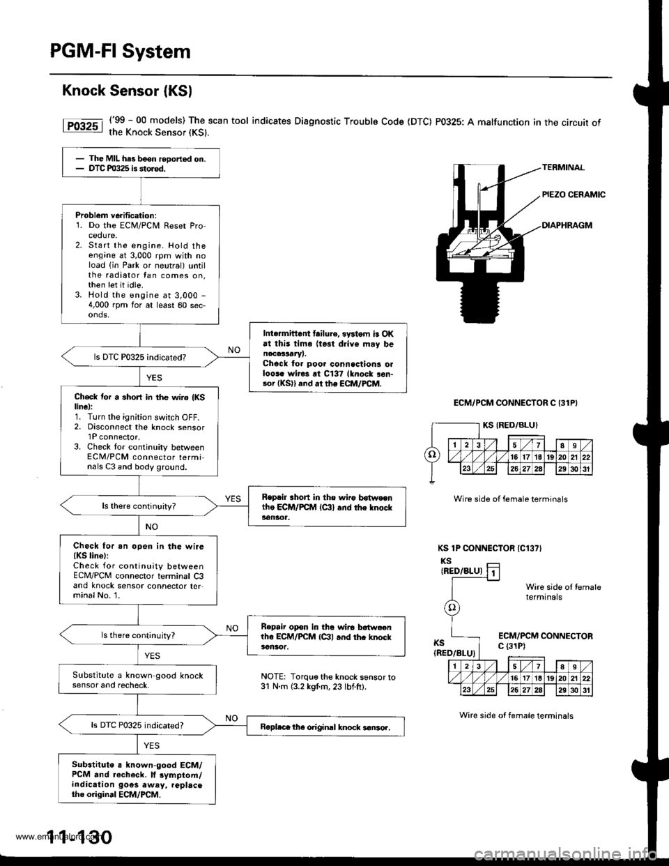
('99 - 00 models) The scan tool indicates Diagnostic Troublo Code (DTC) P0325: A malfunction in the circuit ofthe Knock Sensor (KS).
ECM/PCM CONNECTOR C 131P}
Wire side of female terminals
KS 1P CONNECTOR IC13?'
KSIRED/BLU)
KS(BED/BLU)
Wire side ol femaletermtnals
ECM/PCM CONNECTORc (31P)
- The MIL has been rooorted on.- DTC m325 is storod.
Problem verification:1. Do the ECM/PCir, Reset Procedure,2. Start the engine. Hold theengine at 3,000 rpm with noload (in Park or neutral) untilthe radiator tan comes on,then let it idle.3. Hold the engine at 3,000 -
4,000 rpm for at least 60 sec-onds,
Intermittent lailu.e, 3ystom is OKat thi3 tim. (te3t drive m.y benacalLrYr.Chock to. poor connsctions olloora wiros rt C137 lknock aon-.o. (KS)) and ar the ECM/FCM.
Ch€ck tor a short in the wir6 {KSlinel:1. Turn the ignition switch OFF.2, Disconnect the knock sensorlP connector.3. Check lor continuity betweenECM/PCM connector terminals C3 and body ground.
Replil rhort in the n irg b6{wocntho ECM/PCM lc:ll and the knocks€ngr1.
Check fo..n open in the wire{KS line):Check for continuity betweenECM/PCM connector terminal C3and knock sensor connector ter,minal No. 1.
B.pair opon in the wirc lrotweenlho ECM/PCM lctl and thc knockacnsor.
ls there cont;nuity?
Substitute a known-good knocksensor and recheck.
ls DTC P0325 indicated?Bcpl.ce the original knock 3€nsor,
Substituto a known-good ECM/PCM and .echeck. lf 3ymptom/indication goes away, replacethe original ECM/PCM.
NOTE: Torque the knock s6nsor to31 N.m (3.2 kgl.m, 23 lbf.ft).
1 1-130
Wire side ot female terminals
www.emanualpro.com
Page 437 of 1395
FlywheelClutch Disc, Pressure Plate
Replacement (cont'dl
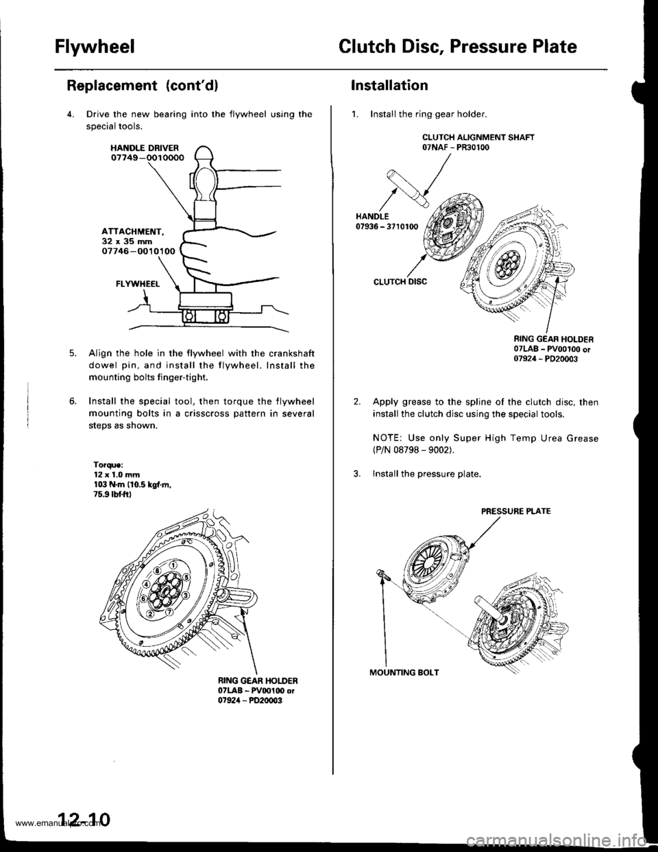
Drive the new bearing
specialtools.
HANOLE DRIVER07749-
ATTACHMET{T-32x35mm07746 -O010100
FLYWHECI-
Align the hole in the flywheel with the crankshaft
dowel pin, and install the flywheel. Install the
mounting bolts finger-tight.
Install the special tool, then torque the flywheel
mounting bolts in a crisscross pattern in several
steps as shown.
Torque:12 x 1.0 mmr03 N.m (10.5 kgl.ln,75.9 tbtftl
into the flywheel using the
12-10
Installation
1. Install the ring gear holder.
CLUTCH ALIGNMENT SHAFT07NAF - PR30100
CLUTCH DISC
RING GEAR HOLDER07LAB _ pvoot(x) or07924 _ PD20003
Apply grease to the spline of the clutch disc, then
install the clutch disc using the special tools.
NOTE: Use only Super High Temp Urea Grease(P/N 08798 - 9002).
lnstall the pressure plate.
PRESSURE PLATE
www.emanualpro.com
Page 438 of 1395
Release Bearing
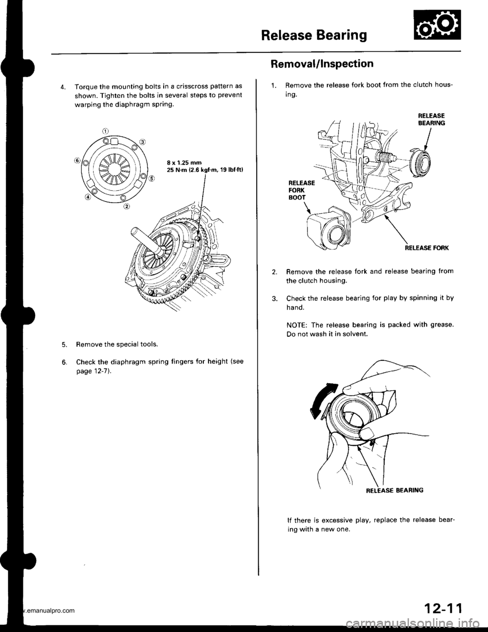
4. Torque the mounting bolts in a crisscross pattern as
shown. Tighten the bolts in several steps to prevent
warping the diaphragm spring.
8 x 1.25 mm25 N.m (2.6 kgf.m, 19lbfft)
Remove the special tools.
Check the diaphragm spring fingers for height (see
page 12-7]'.
5.
6.
Removal/lnspection
1. Remove the release fork boot from the clutch hous-
Ing.
RELEASEBEABING
RELEASEFORKBOOT
\
RELEASE FORK
Remove the release fork and release bearing from
the clutch housing.
Check the release bearing for play by spinning it by
ha nd.
NOTE: The release bearing is packed with grease.
Do not wash it in solvent.
lf there is excessive play, replace the release bear-
ing with a new one.
12-11
www.emanualpro.com
Page 443 of 1395
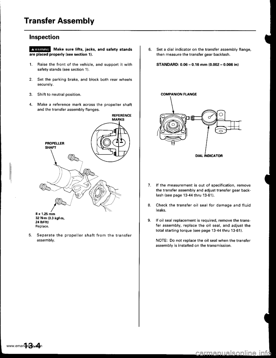
Transfer Assembly
lnspection
@ Make sure tifts, iacks, and satety stands
are placed properly (see section 1).
L Raise the front of the vehicle, and support it with
safety stands (see section 1).
2. Set the parking brake, and block both rear wheels
securely.
3. Shift to neutral oosition.
4. Make a reference mark across the DroDeller shaft
and the transfer assembly flanges,
REFERENCE
8 x 1.25 mm32 N.m (3.3 kg{.m.24 rbf.ftlReplace.
Separate the propeller shaft from the transfer
assemDty.
5.
13-4
6. Set a dial indicator on the transfer assembly flange,
then measure the transfer gear backlash.
STANDARD: 0.06 - 0.16 mm (0.002 - 0.006 in)
COMPAf{ION FI-ANGE
1.lf the measurement is out of specification, remove
the transfer assembly and adjust transfer gear back-
lash (see page 13-44 thru '13-61).
Check the transfer oil seal for damage and fluid
teaKs.
lf oil seal replacement is required, remove the trans-
fer assembly, replace the oil seal, and adjust the
total starting torque (see page 13-44 thru 13-61).
NOTE: Do not replace the oil seal when the transfer
assembly is installed on the transmission.
www.emanualpro.com
Page 474 of 1395
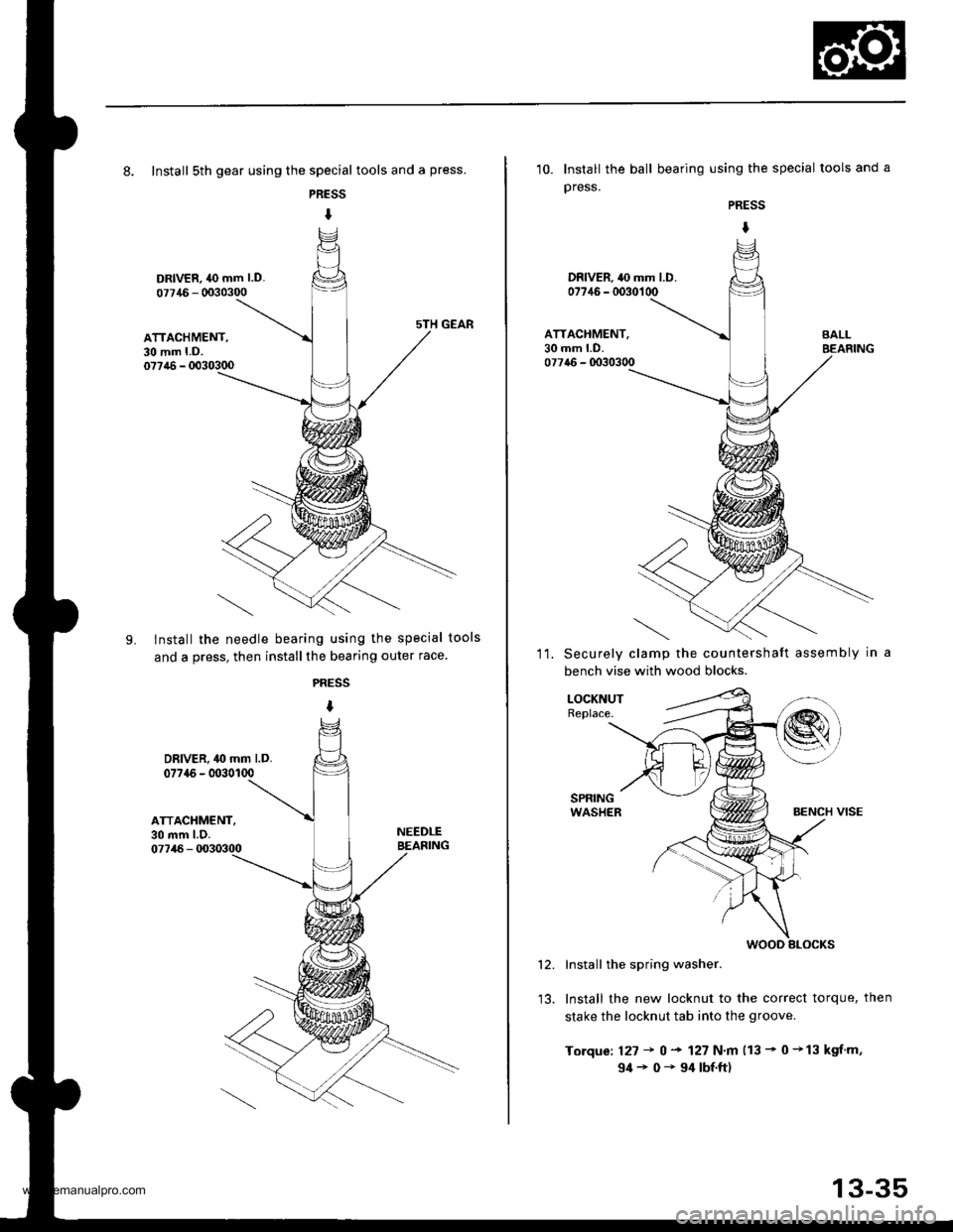
8. Install sth gear using the special tools and a press.
PRESS
I
DRIVER, 40 mm l.D.
07715 - 0030300
ATTACHMENT,30 mm LD.077,16 - 0030300
LInstall the needle bearing using the special tools
and a press, then installthe bearing outer race
PRESS
I
DRIVER. 40 mm l.D.077{6 - 0030100
ATTACHMENT,30 mm l.D.07746 - 0030300
NEEDLEBEASING
10. Install the ball bearing using the special tools and a
press.
PRESS
I
DRIVER. 40 mm LD.07746 - 0030100
ATTACHMENT,30 mm LD.077a6 - 0030300
11.Securely clamp the countershaft assembly in
bench vise with wood blocks.
LOCKNUTReplace.
Install the spring washer.
Install the new locknut to the correct torque, then
stake the locknut tab into the groove.
Torque: 127 + 0 + 127 N.m 113 - 0 +13 kgf.m,
94+0-94|bf.ft)
12.
wooD slocKs
13-35
www.emanualpro.com
Page 480 of 1395
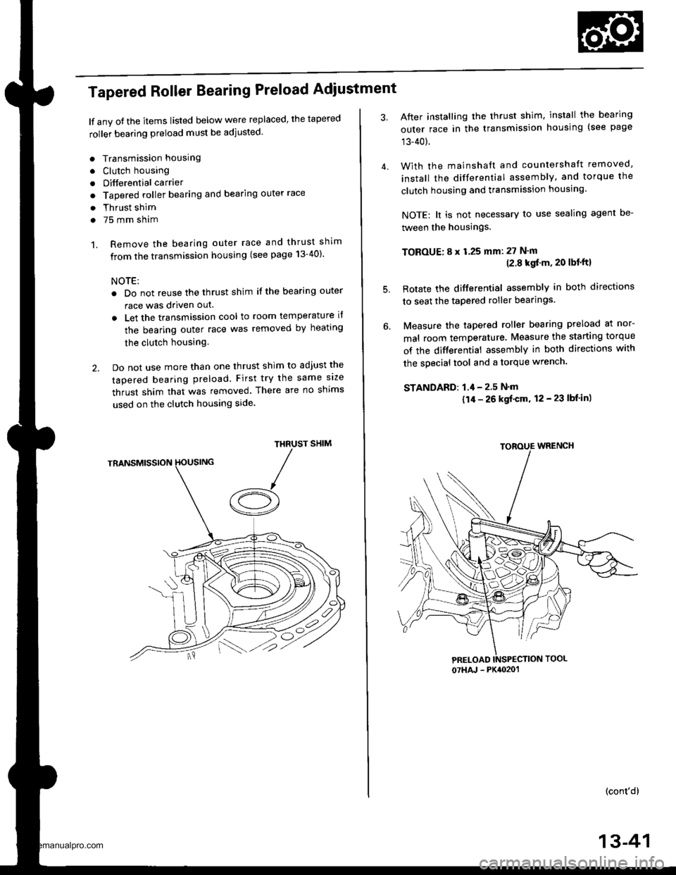
Tapered Roller Bearing Preload Adiustment
lf any oJ the items listed below were replaced, the tapered
roller bearing preload must be adjusted.
. Transmission housing
. Clutch housing
. Differential carrier
o Tapered roller bearing and bearing outer race
. Thrust shim
. 75 mm sham
1. Remove the bearing outer race and thrust shim
from the transmission housing (see page 13-40)'
NOTE:
. Do not reuse the thrust shim if the bearing outer
race was driven out.
. Let the transmission cool to room temperature il
the bearing outer race was removed by heating
the clutch housing.
2. Do not use more than one thrust shim to adjust the
tapered bearing preload. First try the same size
thrust shim that was removed. There are no shims
used on the clutch housing side
SHIMTHRUST
/A
After installing the thrust shim, install the bearing
outer race in the transmission housing (see page
13-40).
With the mainshaft and countershaft removed,
install the differential assembly, and torque the
clutch housing and transmission housing.
NOTE: lt is not necessary to use sealing agent be-
tween the housings.
TOBOUE; 8 x 1.25 mm: 27 N'm(2.8 kgf'm, 20 lbt'ftl
Rotate the differential assembly in both directions
to seat the tapered roller bearings.
Measure the tapered roller bearing preload at nor-
mal room temperature. Measure the starting torque
of the differential assembly in both directions with
the special tool and a torque wrench.
STANDAFD: 1.4 - 2.5 N'm
{1/r - 26 kgf'cm, 12 - 23 lbf in)
(cont'd)
4.
5.
07HAJ - PK4020'�1
13-41
www.emanualpro.com
Page 484 of 1395
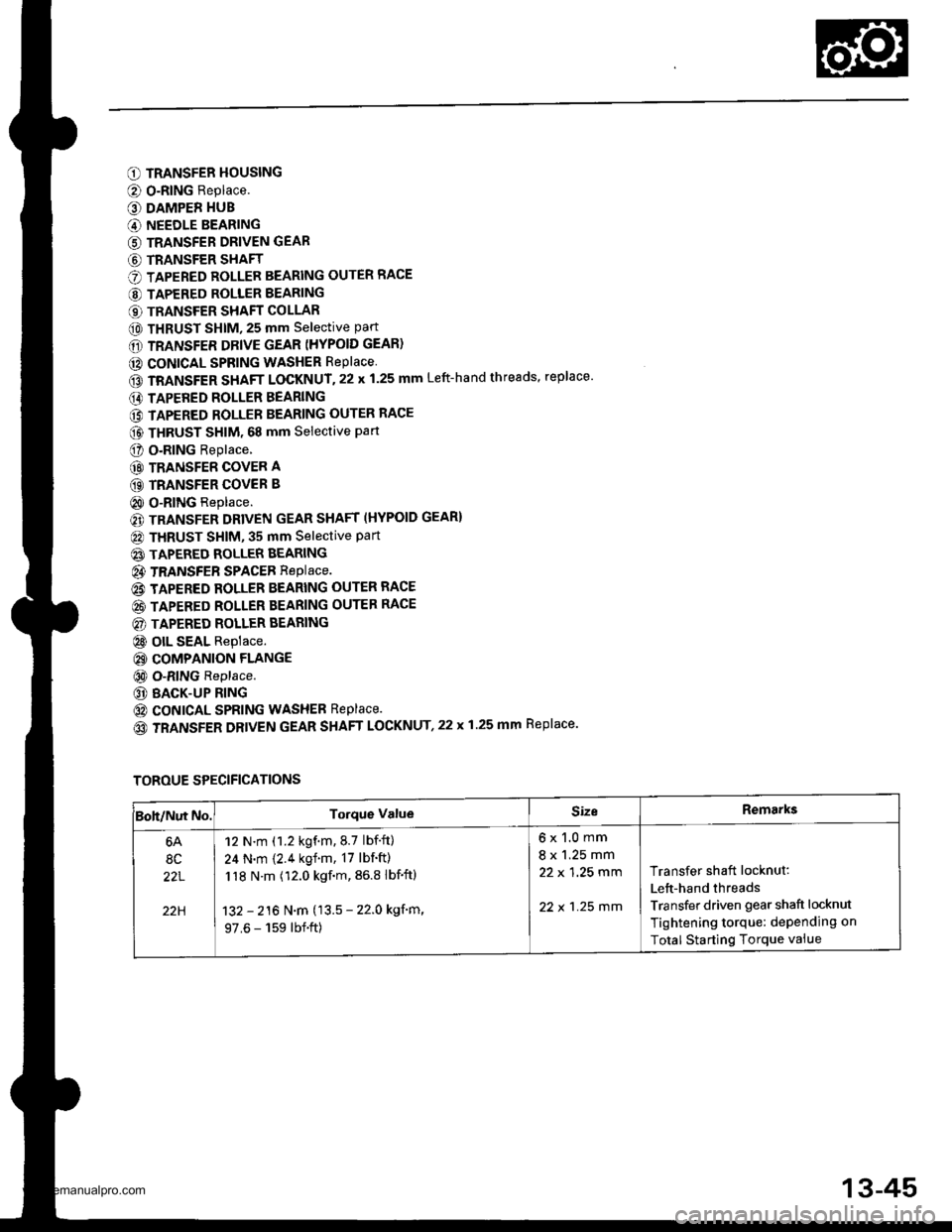
O TRANSFER HOUSING
@ O-RING Replace.
O DAMPER HUB
G) NEEDLE BEARING
G) TRANSFER DRIVEN GEAR
G) TRANSFER SHAFT
O TAPERED ROLLER BEARING OUTER RACE
@ TAPERED ROLLER BEARING
€) TRANSFER SHAFT COLLAR
@ THRUST SHIM, 25 mm selective part
6D TRANSFER DRIVE GEAR (HYPOID GEAR)
@ CONICAL SPRING WASHER RePlace
GD TRANSFER SHAFT LOCKNUT.22 x 1.25 mm Left-hand threads, replace'
E) TAPERED ROLLER BEARING
@ TAPERED ROLLER BEARING OUTER RACE
@ THRUST sHlM. 68 mm selective part
O o.RlNG Replace.
@ TRANSFER COVER A
GD TRANSFER COVER B
@ O-RING Replace.
€) TRANSFER DRIVEN GEAR SHAFT (HYPOID GEAR}
@ THRUST SHIM, 35 mm Selective Part
@ TAPERED ROLLER BEARING
@ TRANSFEB SPACEB RepIace.
@ TAPERED ROLLER BEARING OUTER RACE
@ TAPERED ROLLER BEARING OUTER RACE
@) TAPERED ROLLER BEARING
@ olL SEAL Replace.
@ COMPANION FLANGE
@ O-RING Replace.
@ BACK-UP RING
@ coNtcAL SPRING WASHEB Replace.
(o TRANSFER DRIVEN GEAR SHAFT LOCKNUT,22 x 1.25 mm Replace.
TOROUE SPECIFICATIONS
Boh/Nut No.Torque ValueSizeRemarks
6A
8C
22L
22H
12 N.m (1.2 kgf.m.8.7 lbf.ft)
24 N.m {2.4 kgf.m, 17 lbf'ft)
118 N.m (12.0 kgf.m, 86.8 lbf'ftl
132 - 216 N.m (13.5 - 22.0 kgf'm,
97.6 - 159 lbf.ft)
6x1.0mm
8 x 1.25 mm
22 x 1 ,25 mm
22 x 1 .25 mm
Transfer shaft locknut:
Lett-hand threads
Transfer driven gear shaft locknut
Tightening torque: dePending on
Total Starting Torque vaiue
13-45
www.emanualpro.com
Page 485 of 1395
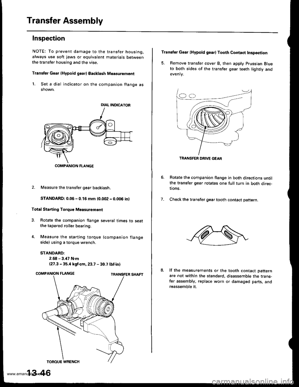
Transfer Assembly
Inspection
NOTE: To prevent damage to the transfer housing,
always use soft jaws or equivalent materials between
the transfer housing and the vise.
Transter Gaar (Hypoid goar) Backlssh M€asurement
1. Set a dial indicator on the companion flange asshown.
2. Measure the transfer gear backlash.
STANDARD: 0.06 - 0.16 mm {0.002 - 0.006 in}
Total Sta.ting Torquo Msasuremont
3. Rotate the companion flange several times to seatthe tapered roller bearing.
4. Measure the starting torque (companion flange
side) using a torque wrench.
STANDARD:
2.68 - 3.47 N.m
{27.3 - 35.4 kgf.cm.23.7 - 30.7 tbt.in)
DIAL INDICATOR
COMPANION FLANGE
13-46
Transfer Gear lHypoid gearl Tooth Contaqt Insp€ction
5. Remove transfer cover B, then apply Prussian Blueto both sides of the transler gear teeth lightly andevenlv.
Rotate the companion flange in both directions untilthe transfer gear rotates one full tuln in both direc-tions.
Check the transfer gear tooth contact pattern.7.
lf the measurements or the tooth contact Datternare not within the standard. disassemble the trans-fer assembly, replace worn or damaged parts, andreassemble it.
TRANSFER DRIVE GEAR
www.emanualpro.com
Page 491 of 1395
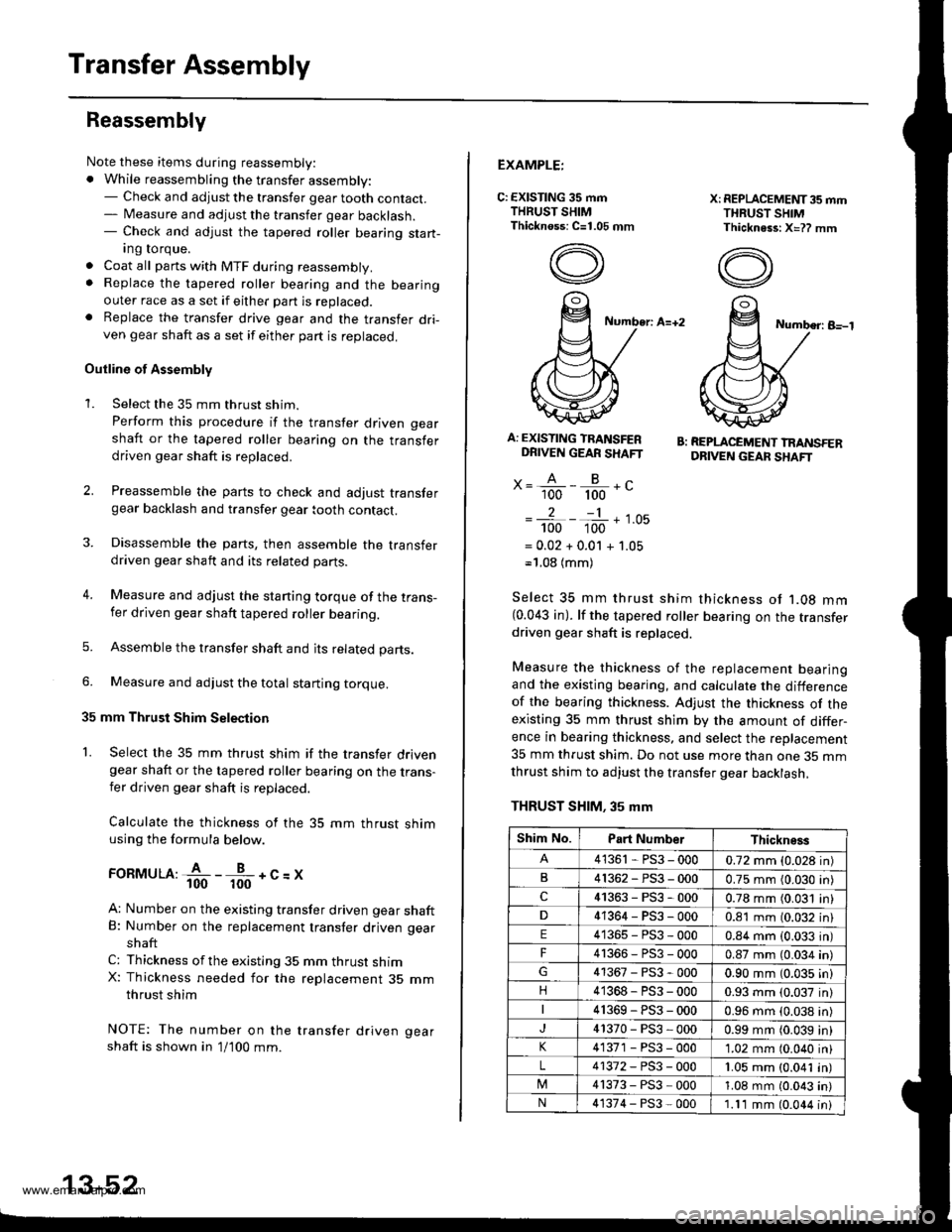
Transfer Assembly
Reassembly
Note these items during reassembly:. While reassembling the transfer assembly:- Check and adjust the transfer gear tooth contact.- Measure and adjust the transfer gear backlash.- Check and adjust the tapered roller bearing start-Ing rorque.
. Coat all parts with MTF during reassembly.. Replace the tapered roller bearing and the bearingouter race as a set if either part is replaced.. Replace the transfer drive gear and the transfer dri-ven gear shaft as a set if either part is replaced,
Outline of Assembly
1.Select the 35 mm thrust shim.
Perform this procedure if the transler driven gear
shaft or the tapered roller bearing on the transferdriven gear shaft is replaced.
Preassemble the parts to check and adjust transfergear backlash and transfer gear tooth contact.
Disassemble the parts, then assemble the transferdriven gear shaft and its related parts.
4. Measure and adjust the staning torque of the trans-fer driven gear shaft tapered roller bearing.
5. Assemble the transfer shaft and jts related parts.
6. Measure and adjust the total starting torque.
35 mm Thrust Shim Seleqtion
1. Select the 35 mm thrust shim if the transfer drivengear shaft or the tapered roller bearing on the trans-fer driven gear shaft is replaced.
Calculate the thickness of the 35 mm thrust shimusing the formula below.
ronrvruu:fi--fr-+c=x
A: Number on the existing transfer driven gear shaftB: Number on the replacement transfer driven gear
shaft
C: Thickness ofthe existing 35 mm thrust shimX: Thickness needed for the replacement 35 mmthrust shim
NOTE: The number on the transfer driven gear
shaft is shown in 1/100 mm.
2.
3.
13-52
EXAMPLE:
C: EXISTING 35 mmTHRUST SHIMThicknoss: C=1.05 mm
X: REPLACEMET{T35 mmTHRUST SHIMThickness: X=?? mm
Number: A=+2Number: B-l
A: EXISTING TRANSFERDRIVEN GEAR SHAFT
x= A - B -.'- 100 100 -
2-1
100 100 '-
= 0.02 + 0.01 + 1.05-'1.08 (mm)
B: REPLACEMENT TRANSFERDRIVEN GEAF SHAFT
Select 35 mm thrust shim thickness ot '1.08 mm(0.043 in). lf the tapered roller bearing on the transferdriven gear shaft is replaced.
Measure the thickness of the replacement bearingand the existing bearing, and calculate the differenceof the bearing thickness. Adjust the thickness of theexisting 35 mm thrust shim by the amount of differ-ence in bearing thickness. and select the replacement
35 mm thrust shim. Do not use more than one 35 mmthrust shim to adjust the transfer gear backlash,
THRUST SHIM. 35 mm
Shim No.Part NumberThickness
41361 - PS3 - 0000.72 mm (0.028 in)
B41362-PS3-0000.75 mm (0.030 in)
c41363-PS3-0000.78 mm (0.031 in)
41364-PS3-0000.81 mm (0.032 in)
E41365-PS3-0000.84 mm (0.033 in)
F4r366-PS3-0000.87 mm (0.034 in)
41367-PS3-0000.90 mm (0.035 in)
n41368-PS3-0000.93 mm (0.037 in)
41369-PS3-0000.96 mm {0.038 in)
41370-PS3-0000.99 mm (0.039 in)
41371 - PS3 - 0001.02 mm (0.040 in)
L41372-PS3-0001.05 mm (0.041 in)
41373-PS3-0001.08 mm (0.043 in)
N41374-PS3-0001.11 mm (0.044 in)
www.emanualpro.com