Ignition control HONDA CR-V 2000 RD1-RD3 / 1.G Repair Manual
[x] Cancel search | Manufacturer: HONDA, Model Year: 2000, Model line: CR-V, Model: HONDA CR-V 2000 RD1-RD3 / 1.GPages: 1395, PDF Size: 35.62 MB
Page 624 of 1395
Electrical Troubleshooting ('98 - 00 Models)
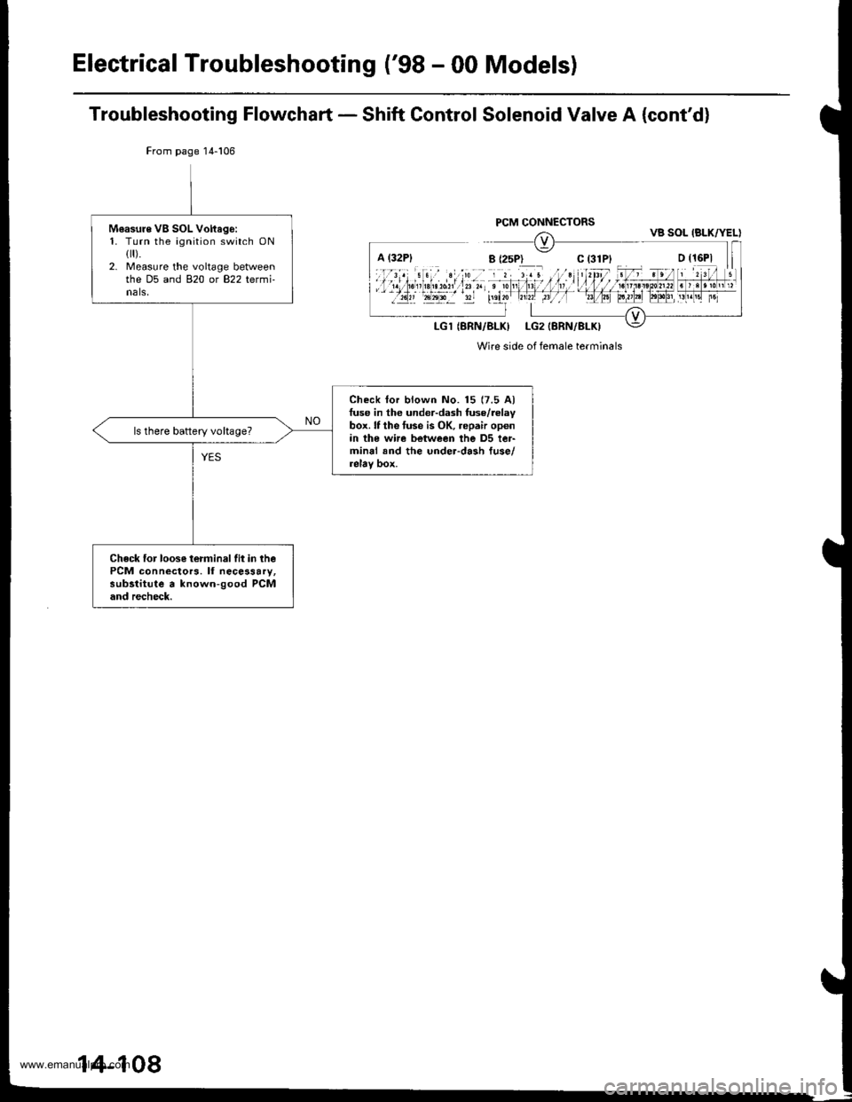
Troubleshooting Flowchart - Shift Control Solenoid Valve A (cont'd)
From page 14-106
Wire side of female terminals
Moasure VB SOL Voftago:1. Turn the ignition switch ONflr).2. Measure the voltage betweenthe D5 and 820 or 822 termi-nals,
Check lor blown No. 15 (7.5 Alfuse in the under-dash fuse/relaybox. lf the tuse is OK, repair openin the wi.e between the D5 ter-minal and the under-dash fuse/relay box.
ls there battery vohage?
Check for loose terminalfit in thePCM connectors. lf necessary,subltitute a known-good PCMand recheck.
VB SOL IBLK/YEL)
14-108
www.emanualpro.com
Page 625 of 1395
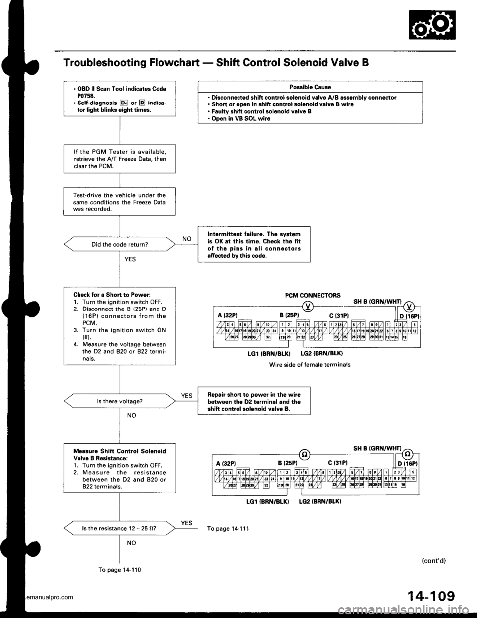
Troubleshooting Flowchart - Shift Control Solenoid Valve B
Po3sible C.us€
.Dt. Short or oDen in shift control solenoid valve B wira' F.ulW shitt cont.ol solonoid valvc B. Opon in VB SOL wir6
LGI {8RN/BLKI
To page 14-111
PCM CONNECTOBS
LGl {BRN/BLKI LG2 {BRN/BLK}
Wire side of lemale terminals
a l32Pl B {2sPl c t3tP}
c (31P1
. OBD ll Scan Tool indicatos CodeP0758.. Self-di.gnosis E or E indica-lor lighf blinb 6ight times.
lf the PGM Tester is available.retrieve the A/f Freeze Data, thenclear the PCM.
Test-drive the vehicle under thesame conditions the Freeze Data
Intermittent failu16. Tha 3yltgmis OK at thi3 time. Check the fitof the Dins in all connectorsaffocted by this codo.
Did the code return?
Check lol o Short to Power:1. Turn the ignition switch OFF.2. Disconnect the B 125P) and D(16P) connectors from thePCM,3. Turn the ignition switch ON0ll.4. Measu.e the voltage betweenthe D2 and 820 or 822 termi-nals.
Ropair short to powor in lhe wirebetwoon the D2 termin.l .nd thoshift cont.ol solenoid vslv6 B.
Measuro Shift Control SolonoidValve I Rosbtance:1. Turn the ignition switch OFF.2. M easu re the resistancebetween tho D2 and 820 or822 terminals.
ls the resistanc€ 12 - 25 O?
To page 14-110
LG2 IBRN/BLKI
(cont'd)
www.emanualpro.com
Page 636 of 1395
Electrical Troubleshooting ('98 - 00 Models)
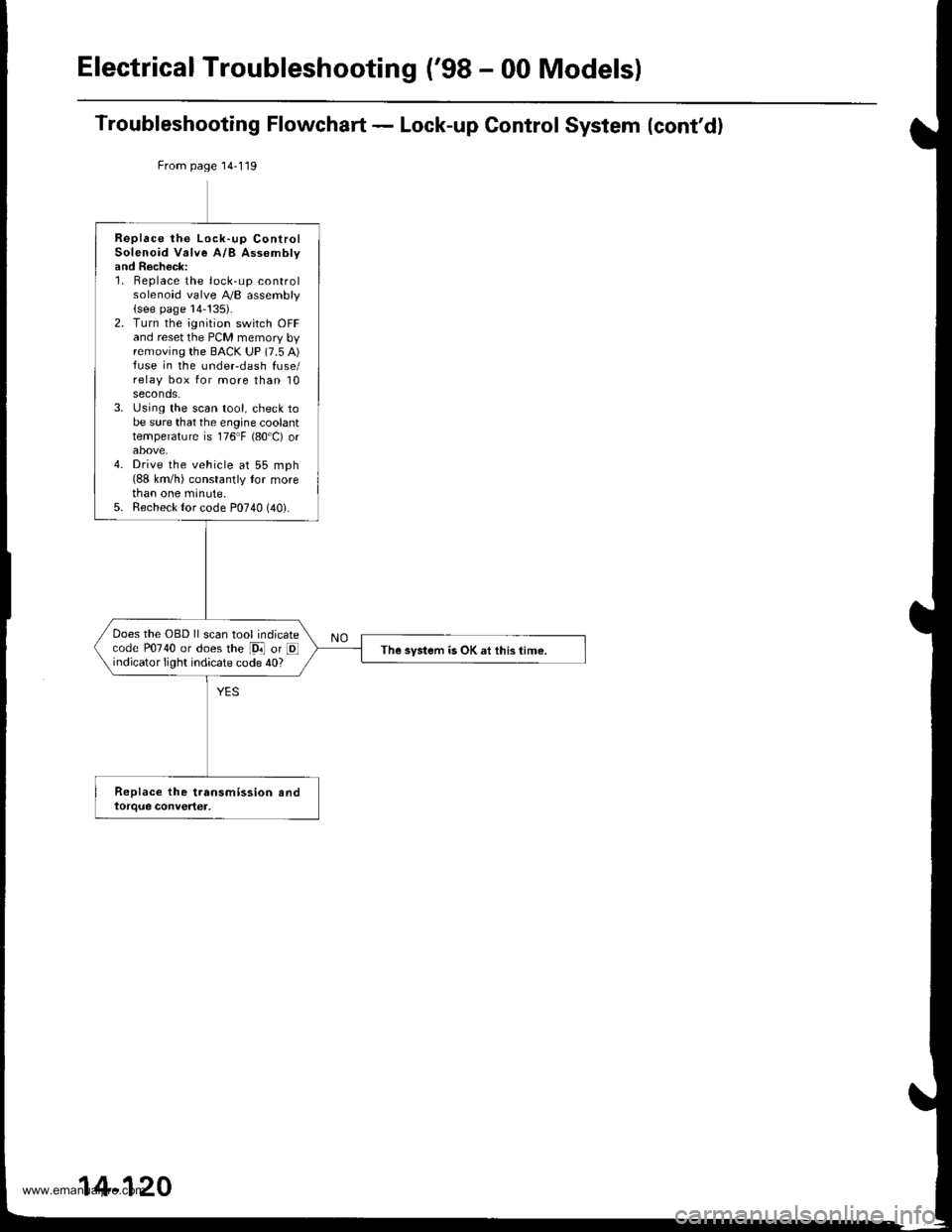
Troubleshooting Flowchart - Lock-up Control System (cont'd)
From page 14-119
Replace the Lock-up ControlSolenoid Valve A/B Assomblyand Recheck:1. Replace the lock-up controlsolenoid valve A,/B assembly(see page 14-!35).2. Turn the ignition switch OFFand reset the PCM memory byremoving the BACK UP (7.5 A)fuse in the undeFdash fuse/relay box for more than 10seconds.3. Using the scan tool, check tobe sure that the engine coolanttemperature is 176"F {80'C) orabove.4. Drive the vehicle at 55 mph(88 km/h) constantly tor morethan one minute.5. Recheck {or code P0740 (40i.
Does the OBD ll scan tool indicatecode P0740 or does the [9i] or Eindicator light indicate code 40?The system is OK at this time.
14-120
www.emanualpro.com
Page 638 of 1395
Electrical Troubleshooting {'gB - 00 Models}
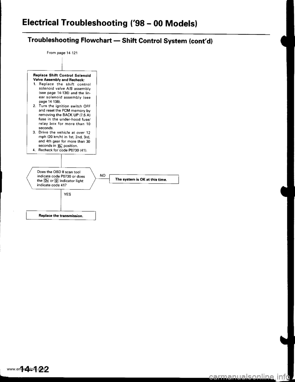
Troubleshooting Flowchart - Shift Control System (cont,d)
From page 14 121
Replace Shilt Cont.ol SolenoidValve A$ambly and Recheck:'1. Replace the shift controlsolenoid valve A/B assembly(see page 14-136) and the lin,ear solenoid assembly (seepage 14138).2. Turn the ignition switch OFFand reset the PCM memory byremoving the BACK UP (7.5 A)tuse in the !nder-hood luse/relay box for more than 10seconos.3. Drive the vehicle at over '12
mph (20 km,/ti) in lst,2nd,3rd,and 4th gear tor more than 30seconds in E position.4. Recheck for code P0730 (41).
Does the OBD ll scan toolindicate code P0730 or doesthe E orE indicator lightindicate code 41?
Tho system is OK .l this tim€.
www.emanualpro.com
Page 642 of 1395
Electrical Troubleshooting ('98 - 00 Modelsl
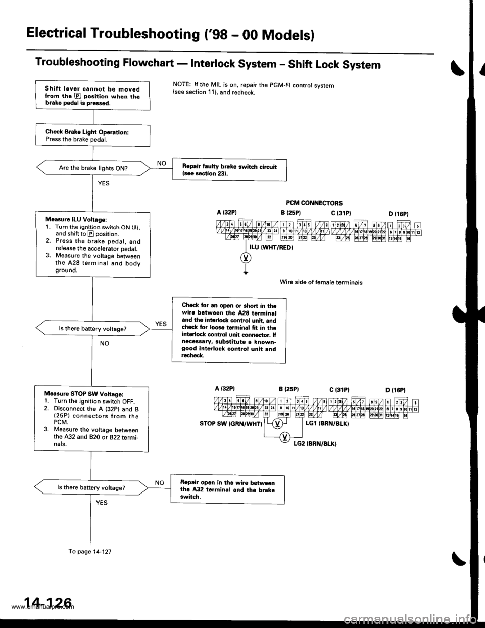
Troubleshooting Flowchart - Interlock System - Shift Lock System
NOTE: li the MIL is on, ropair the PGM-FI controt system{see section 11), and recheck.
PCM CONNECTORS
c l3lPl
Wire side of female lerminals
c t3lPt
D {16P1
1 tttt/ 5t/ 1 a t /tlt 1 t\/t ,/ VVV tl t ttj,r\1e\10l211n . I 3 rholr1 t?m@-@Effilil"
D (lCPl
| 2ttt/ ;t /n) ).tt)/ 1 21:/ tvvvvv nnvl.lnl2
I r r ero
12wE gp]P] polr EI!l!!i r.
a (25P1
LGl {8RN/ALKI
Shift levor cannot be mov6dllom the E po3ition when th6blako pedal is pre3sed.
Ch€ck BJake Light Oporation:Press the brake pedal.
B6pair tlutty brrko 3whch circuitl..e rection 231.Are the brake lights ON?
Me.sure ILU Voltage:1. Turn the ignition switch ON (ll1,and shiftto E position.2. Press the brake pedal, andrelease the accelerator pedal.3. Measure the voltage betweenthe A28 terminal and bodygrouno.
Chock tor an open or short in thewi.o botwoen tha A28 t6rminrland thc intorlod( control unit, rndcheck tor loose torminrl fit in theintorlock conftol unh connoctor. lfnocassaryr aubstitute a known-good intollock control unit rndroch6d(
Mor3uro STOP SW vohsgo:1. Turn the ignition switch OFF.2. Disconnect the A (32P1 and B(25P) connectors {rom thePCM.3. Measure the voltage betweenthe A32 and 820 or 822 termi-nals,
Repair op6n in tho wir€ betwsenthe A32 t6.minal and th6 brake3witch.
ls there battery voltage?
fo page 14-121
14-126
www.emanualpro.com
Page 644 of 1395
Electrical Troubleshooting ('98 - 00 Modelsl
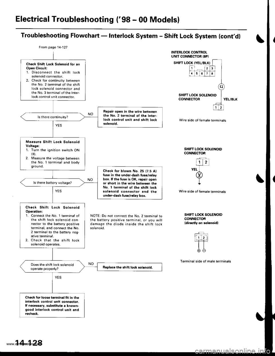
Troubleshooting Flowchaft - Interlock System - Shift Lock System {cont'dl
INTERLOCK CONTROLUNTT CONNECTOR ISPI
SHIFT LOCK IYEL/BLX
SHIFT LOCK tCONNECTOR
{YEL/BLKI
123
1678
o
LOCK SOLENOID
12
YEL/BLK
Wire side of female termtnals
SHIFT LOCK SOI.ENOIDCONNECTOR
"l z-irr-
YEL ](v)
I!
Wire side of female terminsls
NOTE: Do not connect the No. 2 terminal tothe battery positive terminal, or you willdamage the diode inside the shift rocKsolenoid.
SHIFT LOCK SOLENOIOCONNECTOR(dir.ctly on $lenoidl
Terminal side of male terminals
From page 14-127
Check Shift Lock Solenoid tor anOpen Ci.cuit:1. Disconnect the shilt locksolenoid connector,2. Check for continuity betweenthe No. 2 terminal of the shiftlock solenoid connector andthe No. 3 terminal of the interlock control unit connector,
Repair open in the wir6 betweenth€ No. 2 termin.l oI ihe inter-lock control unit and ahift locksolenoid.
ls there continuity?
Measu.e Shift Lock SolenoidVoltage:1. Turn the ignition switch ONflr).2. Measure the voltage betweenthe No. 1 terminal and bodyground.
Check lor blown No.25 {7.5 Alfuse in the underdash fuse/relaybox. It the tuse i3 OK, repair oponor short in lhe wire betw€en theNo. 1 terminal of tho shift locksolenoid connector rnd theunder-dash fuso/r€lay box,
ls there battery voltage?
Check Shift Lock SolenoidOperrtion:1. Connect the No. 1 terminal ofthe shitt lock solenoid connector to the battery positiveterminal, and connect the No,2 terminal to the battery neg,ative terminal.2. Check that the shift locksolenoid operates.
Does the shift lock solenoidoperate properly?Roplace the shift lock solenoid.
Check tor looso torminal tit in th6interlock control unit connector.lf necessary, substitute a known-good int€rlock control unil andrecheck.
14-128
www.emanualpro.com
Page 646 of 1395
Electrical Troubleshooting ('98 - 00 Models)
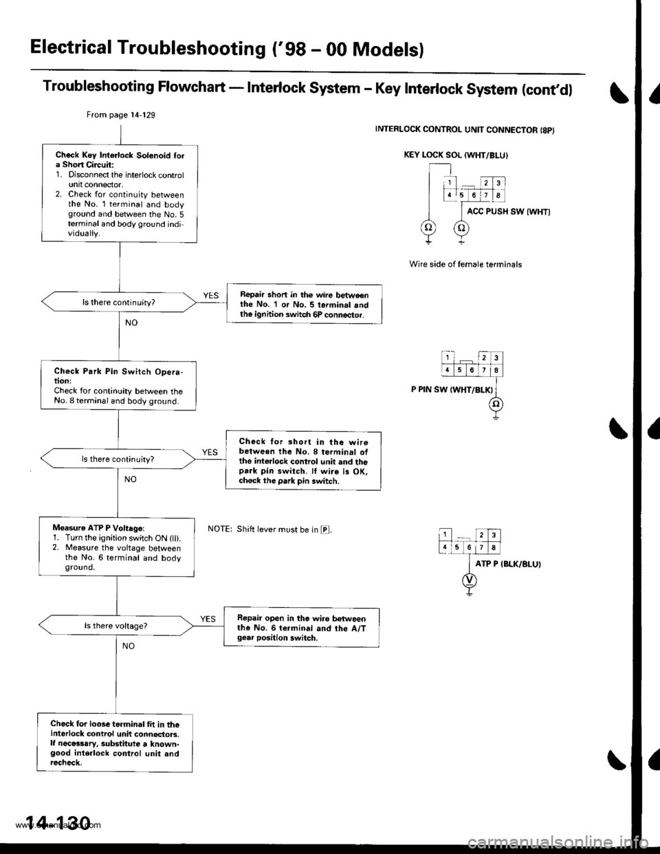
Troubleshooting Flowchart - Interlock System - Key Interlock System (cont,dl
INTERLOCK CONTROL UNIT CONNECTOR {8PI
KEY LOCK SOL (WHT/BI-U}
ACC PUSH SW {WHT)
Wire side of female terminals
ATP P IBLK/BLUI
From page 14'129
Shift lever must be in E.
Check Key Intorlock Solonoid tola Short Circuit:1. Disconnect the interlock controlunit connector,2. Check for continuity betweenthe No. l terminal and bodyground and between the No.5terminal and body ground individually.
Repair shon in thc wire betweonthe No. 1 or No. 5 terminal andth€ ignhion switch 6P connector.
ls there continuity?
Check Park Pin Switch Opera-tion:Check for continuity between theNo. I terminal and body ground.
Check for short in the wir6between the No. 8 terminal ofthe int€rlock control unit and thopark pin switch. ll wire is OK,ch6ck the park pin switch.
ls there continujty?
Moasure ATP P Voftegel1. Turn the ignition switch ON (lli.2. Measure the voltage betweenthe No. 6 terminal and bodyground.
Repair open in the wiro betweenthe No. 6 termin.l and the A/Tgear position 3witch.
Check for looseterminal fit in th€interlock control unit connoctors.lf necosssry, substitute t known-good interlock control unit andrecheck.
14-130
www.emanualpro.com
Page 657 of 1395
![HONDA CR-V 2000 RD1-RD3 / 1.G Repair Manual
8. Set the control shaft to E] position. then install the
A,/T gear position switch on it.
CONTROL SHAFT
Install the AyT gear position switch cover and har-
ness clamp on the end cover.
Connect the HONDA CR-V 2000 RD1-RD3 / 1.G Repair Manual
8. Set the control shaft to E] position. then install the
A,/T gear position switch on it.
CONTROL SHAFT
Install the AyT gear position switch cover and har-
ness clamp on the end cover.
Connect the](/img/13/5778/w960_5778-656.png)
8. Set the control shaft to E] position. then install the
A,/T gear position switch on it.
CONTROL SHAFT
Install the Ay'T gear position switch cover and har-
ness clamp on the end cover.
Connect the A,/T gear position switch connector.
then install it on the connector bracket.
Turn the ignition switch ON (ll). Move the shift lever
through all gears, and check the AfI gesr position
switch synchronization with the A/T gear position
indicator.
9.
10.
11.
A/TGEARPOSMON A/T GEAR POSITIONINDICATOR INDICATOR'99 - 00 MODELS '�97 - 98 MOOELS
12, Start the engine. Move the shift lever through all
gears. and verify the following:
. The shift lever cannot be moved to E] position
from E position unless the shift lever is pulled.
. The engine will not start in any position other
than E or E.. The back-up lights come on when the shift lever
is in El position.
14-141
www.emanualpro.com
Page 658 of 1395

A/T Gear Position Indicator
1.
f nput Test -'97 - 98 Models
Remove the gauge assembly from the dashboard (see section 20). and disconnect the 14P connector from the gauge
assemblv (see section 23),
Inspect the connector and socket terminals to be sure they are all making good contact.
. lf the terminals are bent, loose, or corroded, repairthem as necessary, and recheck the system.. lf the terminals look OK, make the following input tests at the 14P connector.- lf I test indicates a problem, find and correct the cause, then recheck the system.- lf all the input tests prove OK, but the indicator is faulty. replace the printed circuit board,
GAUGE ASSEMBLY 14P CONNECTOR
Wire side of female terminals
CavityWirs
ColorTest ConditionTest: Desir€d ResultPossible Cause
{lf rosult is not obtainod)
YEL
lgnition switch ON (ll)Check for voltage to ground:
There should be battery voltage,
. Blown No. 25 (7.5 A) fuse in the
under-dash fuse/relay box. An open in the wire
RE D/BLKCombination light
switch ON and dash
lights brightness con-
trol dial on full bright
Check for voltage between No. 2
and No. 3 terminals;
There should be battery voltage.
Blown No. 47 (7.5 A) fuse in the
under-dash fuse/relay box
Faulty combination Iight switch
Faulty dash iight brightness
controller
An open in the wire
RED
4BLUShift lever in ECheck for continuity to ground:
There should be continuity.
NOTE: There should be no continu-
ity in any other shift lever position.
' Faulty Ay'T gear position switch. An open in the wireBRNShift lever in E
7YELShift lever in @
8BLKUnder all conditionsCheck for continuity to ground:
There should be continuity
. Poor ground {G401). An open in the wire
9GRN/BLK
lgnition switch ON {ll)
and shift lever in any
position except E
Check for voltage to ground:
There should be battery voltage
for two seconds after the ignition
switch is turned ON {ll), and less
than 1 V two seconds later,
' Faulty PCM. An open in the wire
10GRNShift lever in ECheck for continuity to ground:
There should be continuity.
NOTE: There should be no conti-
nuity in any other shift lever posi-
UOn.
. Faulty A,ff gear position switch. An open in the wire1'lREDShift lever in @
12WHTShift lever in E
BLVBLU
Shift lever in ENOTE: Do not push
the brake pedal.
14LT GRN
lgnition switch ON { ll)
and shift lever in any
position except E and
E
Check for voltage to ground:
There should be about 5 V.
. Faulty PCM. An open in the wire
14-142
www.emanualpro.com
Page 659 of 1395

L
Input Test -'99 - 00 Models
Remove the gauge assembly from the dashboard {see section 20), and disconnect the 14P connector from the gauge
assembly (see section 23).
Inspect the connector and socket terminals to be sure they are all making good contact.
a lf the terminals are bent. loose, or corroded. repair them as necessary. and recheck the system.
. lf the terminals look OK, make the following input tests at the 14P connector.- lf a test indicates a problem, find and correct the cause, then recheck the system.- lf all the input tests prove OK, but the indicator is faulty, replace the printed circuit board.
GAUGE ASSEMBLY 14P CONNECTOR
Wire side of female terminals
CavityWire
ColorTest ConditionTest: Desired ResuhPossible Caus6
{lf resutt is not obtainod)
1YEL
lgnition switch ON (ll)Check for voltage to ground:
There should be battery voltage.
. Blown No.25 (7.5 A) fuse in the
under-dash fuse/relay box. An open in the wire
2RE D/BLK
Combination light
switch ON and dash
lights brightness con-
trol dial on full bright
Check for voltage between No. 2
and No.3 terminals:
There should be battery voltage.
Blown No. 47 {7.5 A) fuse in the
under-dash fuse/relay box
Faulty combination light switch
Faulty dash light brightness
controller
An open in the wire
5RED
BRNShift lever in ECheck for continuity to ground:
There should be continuity.
NOTE: There should be no continu-
ity in any other shift lever position.
. Faulty A/T gear position switch. An open in the wire7YELShift lever in E
'10BLUShift lever in E
LT BLU
lgnition switch ON (ll),
shift lever in E. and
Over-Drive is OFF bypressing O/D switch.
Check for continuity to ground:
There should be continuity.
Faulty O/D switch
Faulty A/T gear position switch
Faulty PCM
An open in the wire
8BLKUnder all conditionsCheck for continuity to ground:
There should be continuity
. Poor ground (G401)
. An open in the wire
9a:FI\|/Et| ta
lgnition switch ON (ll)
and shift lever in any
position except E
Check for voltage to groundl
There should be battery voltage
for two seconds after the ignition
switch is turned ON (ll). and less
than 1 V two seconds later.
. Faulty PCM. An open in the wire
11REDShift lever in SCheck for continuity to ground:
There should be continuity.
NOTE: There should be no conti-
nuity in any other shift lever posi-
Iton.
. Faulty A/T gear position switch. An open in the wire12WHTShift lever in E
BLI(BLU
Shift lever in ENOTE: Do not push
the brake pedal.
14LT GRN
lgnition switch ON (ll)
and shift lever in any
position except E and
E
Check for voltage to groundl
There should be about 5 V,
. Faulty PCM. An open in the wire
14-143
www.emanualpro.com