Valve clea HONDA CR-V 2000 RD1-RD3 / 1.G Repair Manual
[x] Cancel search | Manufacturer: HONDA, Model Year: 2000, Model line: CR-V, Model: HONDA CR-V 2000 RD1-RD3 / 1.GPages: 1395, PDF Size: 35.62 MB
Page 939 of 1395

6.
7.
8.
lf the clearance between the gauge body and
adjusting nut is 0.4 mm (0.02 in), the pushrod-to-
piston clearance is 0 mm. However. if the clearance
between the gauge body and adjusting nut is 0 mm,
the pushrod-to-piston clearance is 0.4 mm (0.02 in)
or more. Therefore it must be adjusted and
recheck€d.
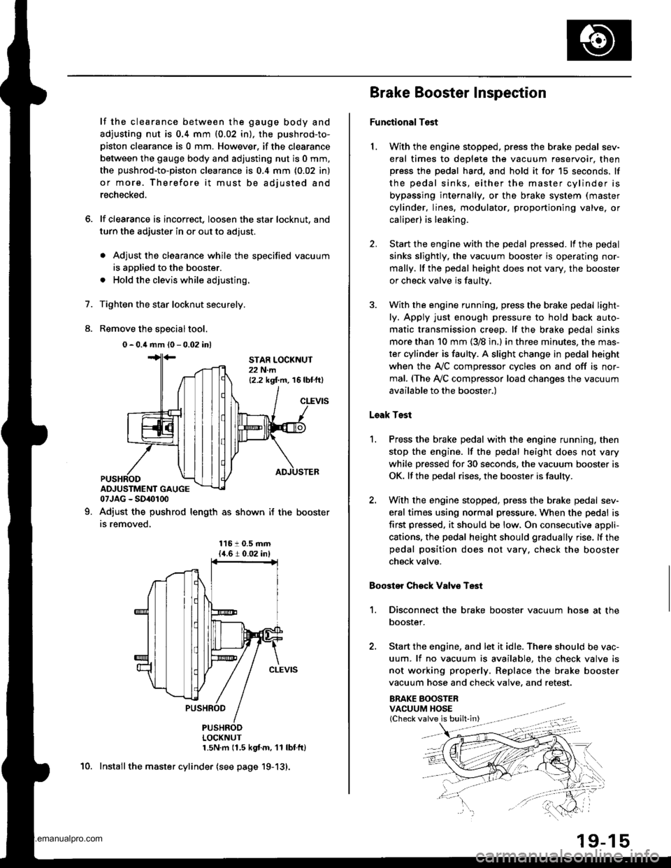
lf clearance is incorrect, loosen the star locknut, and
turn the adjuster in or out to adjust.
. Adjust the clearance while the specified vacuum
is applied to the booster.
. Hold the clevis while adjusting.
Tighten the star locknut securely.
Remove the special tool.
0 - 0.4 mm (0 - 0.02 inl
Adjust the pushrod length as shown if the
is removed,
booster
11610.5 mm{4.6 t 0.02 inl
PUSHRODLOCKNUT1.5N.m 11.5 kgf.m. '11 lbtfl)
Install the master cylinder (see page 19-13).
9.
STAR LOCKNUT22 N.m12.2 kgt m. 16 lbtftl
10.
(Check valve is built-in)
Brake Booster Inspection
FunctionalTest
1. With the engine stopped, press the brake pedal sev-
eral times to deplete the vacuum reservoir. thenpress the pedal hard, and hold it for 15 seconds. lf
the pedal sinks, either the master cylinder is
bypassing internally, or the brake system (master
cylinder, lines, modulator, proportioning valve. or
caliper) is leaking.
2. Start the engine with the pedal pressed. lf the pedal
sinks slightly. the vacuum booster is operating nor-
mally. lf the pedal height does not vary, the booster
or check valve is faultv.
3. With the engine running, press the brake pedal light-
ly. Apply just enough pressure to hold back auto-
matic transmission creep. lf the brake pedal sinks
more than 10 mm (3/8 in.) in three minutes, the mas-
ter cylinder is faulty. A slight change in pedal height
when the Ay'C compressor cycles on and off is nor-
mal. (The Ay'C compressor load changes the vacuum
available to the booster.)
Leak Test
1.Press the brake pedal with the engine running, then
stop the engine. lf the pedal height does not vary
while pressed for 30 seconds, the vacuum booster is
OK. lf the pedal rises, the booster is faulty.
With the engine stopped, press the brake pedal sev-
eral times using normal pressure. When the pedal is
first pressed. it should be low, On consecutive appli-
cations, the pedal height should gradually rise. lf thepedal position does not vary. check the booster
check valve.
Boostor Chock Valve Test
1. Disconnect the brake booster vacuum hose at the
booster.
2. Start the engine, and let it idle. There should be vac-
uum. lf no vacuum is available, the check valve is
not working properly. Replace the brake booster
vacuum hose and check valve. and retest.
ERAKE BOOSTERVACUUM HOSE
www.emanualpro.com
Page 1141 of 1395

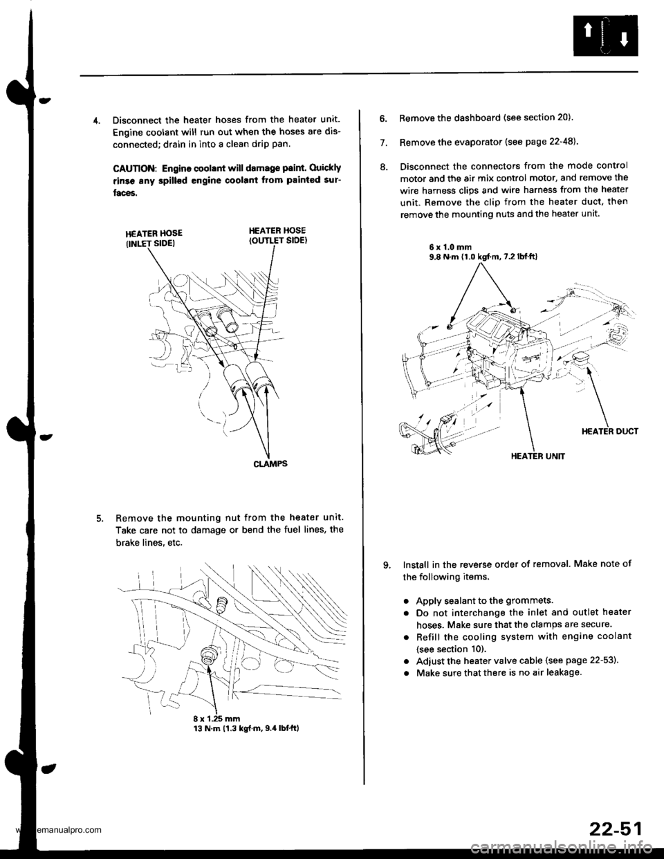
4. Disconnect the heater hoses from the heater unit.
Engine coolant will run out when the hoses are dis-
connected; drain in into a clean drip pan.
CAUTION: Engino coolant will damage p8int. Ouickly
rinse any spill€d engine coolant Itom painted sur-
faces.
HEATER HOSEIOUTLET SIDE)
Remove the mounting nut from the heater unit.
Take care not to damage or bend the fuel lines, the
brake lines. etc.
CLAMPS
13 N.m 11.3 kg{.m,9.4 lbtftl
22-51
7.
ll.
Remove the dashboard (see section 20).
Remove the evaporator (see page 22-48).
Disconnect the connectors from the mode control
motor and the air mix control motor, and remove the
wire harness clips and wire harness from the heater
unit. Remove the clip from the heater duct, then
remove the mounting nuts and the heater unit
6x1.0mm9,8 N.m (1.0 kgt m,7.2lblft)
qInstall in the reverse order of removal. Make note of
the following items.
a
a
a
a
Apply sealant to the grommets.
Do not interchange the inlet and outlet heater
hoses. Make sure that the clamps are secure.
Refill the cooling system with engine coolant
{see section 10).
Adiust the heater valve cable (see page 22-53).
Make sure that there is no air leakage.
HEATER UNIT
www.emanualpro.com
Page 1148 of 1395

A/C System Service
Pressure Test Chart
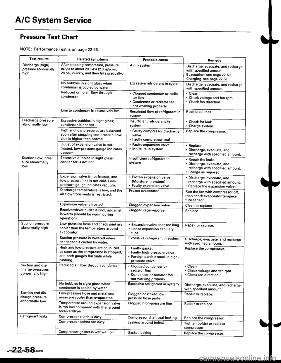
NOTE: Performance Test is on page 22-56.
Test resultsRelatad symptomsPrcbable caus€Remody
Discharge (high)pressure 6bnormallyhagh
After stopping compressor, pressuredrops to about 200 kPa 12.0 kgtlcm,,28 psi) quickly, and then lalls gradualty.
Air in systemDischarge, evacuate, and rechargewith specified amount.Evacuation: see page 22-60Charging: see page 22-61No bubbles in sight glass whencondenser is cooled by waterExcessive refrigerant in systemDischarge, evacuate, and rechargewith specilied amount.Reduced or no air flow throughcondenser. Clogged condenser or radia-tor fins. Condenser or radiator fannot wo.king properly
CleanCheck voltage and fan rpm.Check fan direction.
Line to condensor is excossivelv hot.Restricted flow of relrigerant insy$emFestricted lines
Discharge pressureabnormally lowExcessive bubbles in sight glass;condenser is not hot.Insufficient retrigerant inCheck for leak.Charge system.High and low pressures are balancedsoon after stopping compressor. Lowside is higher than normal.
. Faulty compressor discharge
. Faulty compressor seal
Replace the comprossor.
Outlet ot expansion valve is notfrosted, low-pressure gauge indicates
' Faulty expansion valve. Moisture in system. Replace. Discharge, evacuate, andrecharge with specified amount.Suction {low) pros,sure abnormallyExcessive bubbles in sight glass;condenser is not hot.Insufficiont relrigerant inRepair the leaks.Discharge, evacuate, andrecharge with specified amount.Charge as r€quired.Expansion valve is not frosted, andlow-pressure line is not cold. Low-pressure gauge indicates vacuum.
' Frozen expansion valvelMoisture in system). Faulty expansion valve
. Discharge, evacuate, andrecharge with specitied amount.. Replace th€ expansion valve.Discharge temperature is low, and theair llow trom vents is restricted.Frozen evaporatorRun the fan with compressor off,then check evaporator tempera,ture sensor.Expansion valve is frosted.Clogged expansion valveClean or replace.Feceiver/dryer outlet is cool, and inlotrs w6rm (should be warm duringoperation).
Clogged receiver/dryerReplace
Suction pressureabnormally highLow-pressure hose and check joint arecooler than tho temperature aroundevaporator.
. Expansion valve open too long. Loose expansion capillarytube
Repair or roplace.
Suction pressure is lowored whencondenser is cooled by water.Excessive refrigerant in systemDischarge, evacuate, and rechargewath specified amount.High and low-pressure are equalizedas soon as tho compressor is stopped,and both gauges tluctuate whilerunning.
Faulty gasketFaulty high-pressure valveForeign panicle stuck in high-
Replace the compressor.
Slction and dis,charge pressutesabnormally high
Reduced air flow through condens€r,. Clogged condenser orradiator tins. Condenser or radiator fannot working properly
CleanCheck voltage and fan rpm.Check Ian direction.
No bubbles in sight glass whencondenser is cooled by walerExcessive refrigerant jn systemDischarge, evacuate, and rechargewith specified amount.Suction and dis-charge pressureabnormally low
Low-pressure hose and motalendareas are cooterlhan evaporator.Clogged or kinked low-pressure hose pansRepair or replace.
Temperature around expansion valvers too low compared with that aroundClogged high-pressure lineRepair or replace.
Refrigerant leaksCompressor clutch is diny.Compressor shaft seal leakingReplace the compressor.Compressor boltls) are dirty.Leaking around bolt(s)Tighton bolt{s) or replacecompressor.Compressor gasket is wet with oil.Gasket leakingReplace the compressor,
www.emanualpro.com
Page 1158 of 1395

Compressor
Thermal Protector Replacement
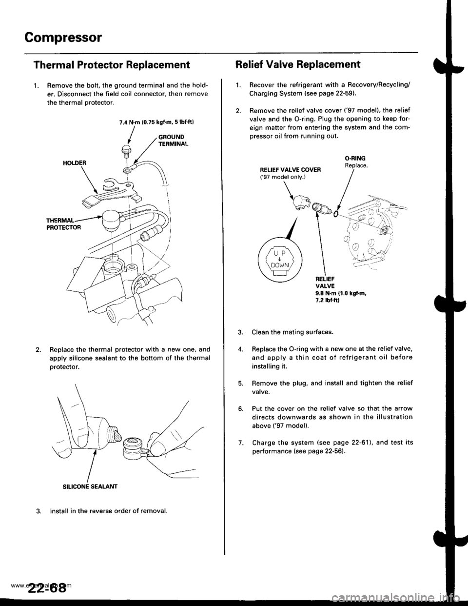
1. Remove the bolt, the ground terminal and the hold-
er. Disconnect the field coil connector. then remove
the thermal Drotector.
7.4 N.m (0.75 kgrf.m,5lbf ftl
GROUNDTERMINAL
ReDlace the thermal protector with a new one, and
apply silicone sealant to the bottom of the thermal
orotector,
3. lnstall in the reverse order of removal.
SILICONE SEALANT
22-68
Relief Valve Replacement
l.Recover the refrigerant with a Recovery/Recycling/
Charging System (see page 22-59).
Remove the relief valve cover ('97 model), the relief
valve and the O-ring. Plug the opening to keep for-
eign matter from entering the system and the com-
pressor oil from running out.
O.RINGReplace.
RELIEFVALVE9.8 N.m {1.0 hgf.m,7.2 rbr.ftl
Put the cover on the relief valve so that the arrow
directs downwards as shown in the illustration
above ('97 model).
Clean the mating surfaces.
Replace the O-ring with a new one at the relief valve,
and apply a thin coat of refrigerant oil before
installing it.
Remove the plug. and install and tighten the relief
valve.
7. Charge the system (see page 22-61), and test its
performance (see page 22-561r.
www.emanualpro.com