No start HONDA CR-V 2000 RD1-RD3 / 1.G Manual PDF
[x] Cancel search | Manufacturer: HONDA, Model Year: 2000, Model line: CR-V, Model: HONDA CR-V 2000 RD1-RD3 / 1.GPages: 1395, PDF Size: 35.62 MB
Page 348 of 1395
PGM-FI System
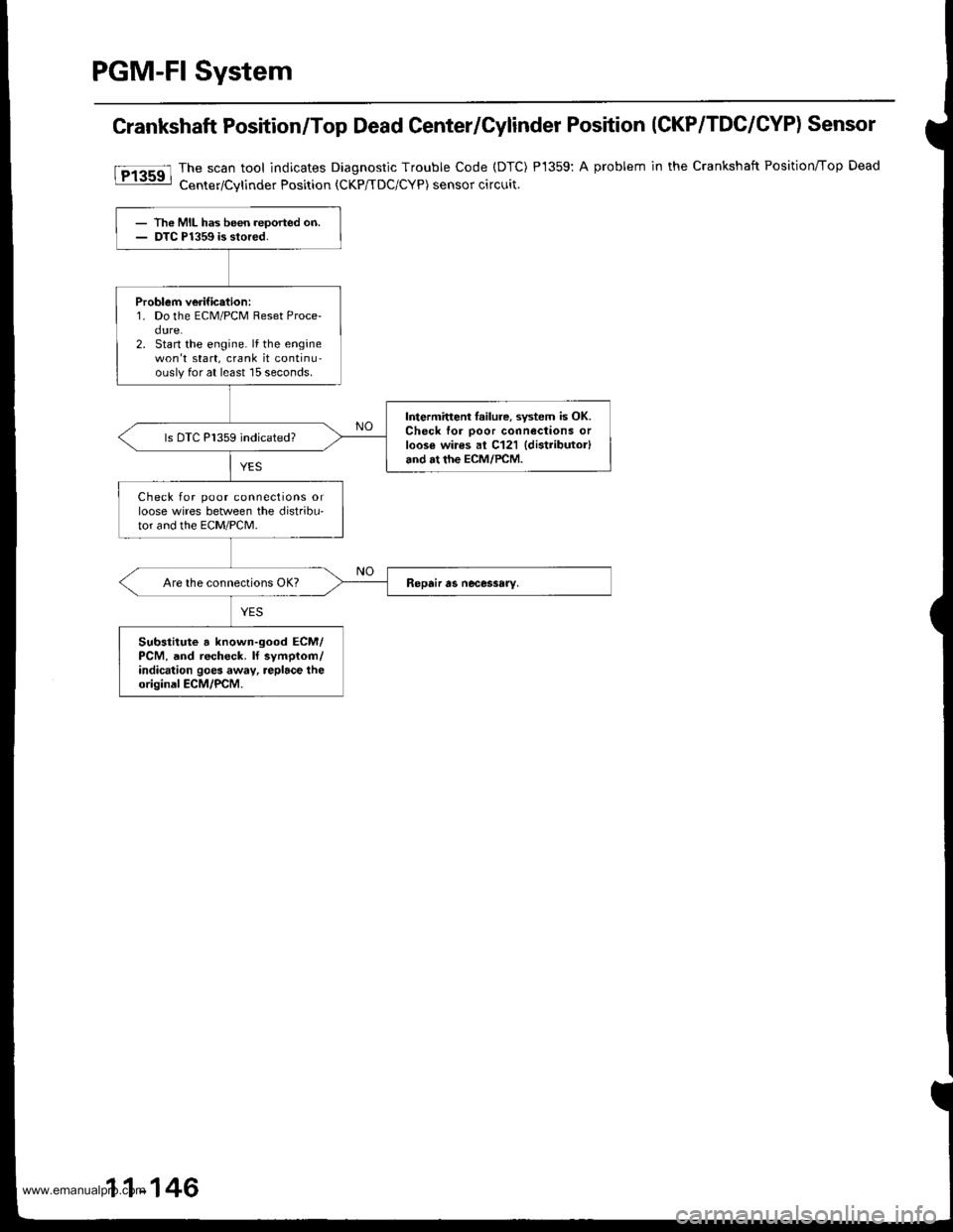
Crankshaft Position/Top Dead Center/Cylinder Position (CKP/TDC/CYP) Sensor
The scan tool indicates Diagnostic Trouble Code (DTC)
Center/Cvlinder Position tCKP/TDC/CYP) sensor circuit.
P1359:A problem in the Crankshaft Position/Top Dead
- The MIL has been reoorted on.- DTC P1359 is stored.
Problem verific.tion:1. Do the ECM/PCM Reset Proce-dure.2. Start the engine. lf the enginewon't start, crank it continu-ouslyfor at least 15 seconds.
Intermitteni lailure, system is OK.Check for ooor connections orloos€ wires al C121 {distributor}and at the ECM/PCM.
ls DTC P1359 indicated?
Check for poor connections orloose wires between the distribu'tor and the EcM/PcM.
Substitute a known-good ECM/PCM, and recheck. ll symplom/indication goes away, replace theoriginal ECM/PCM.
11-146
www.emanualpro.com
Page 351 of 1395
ldle Control System
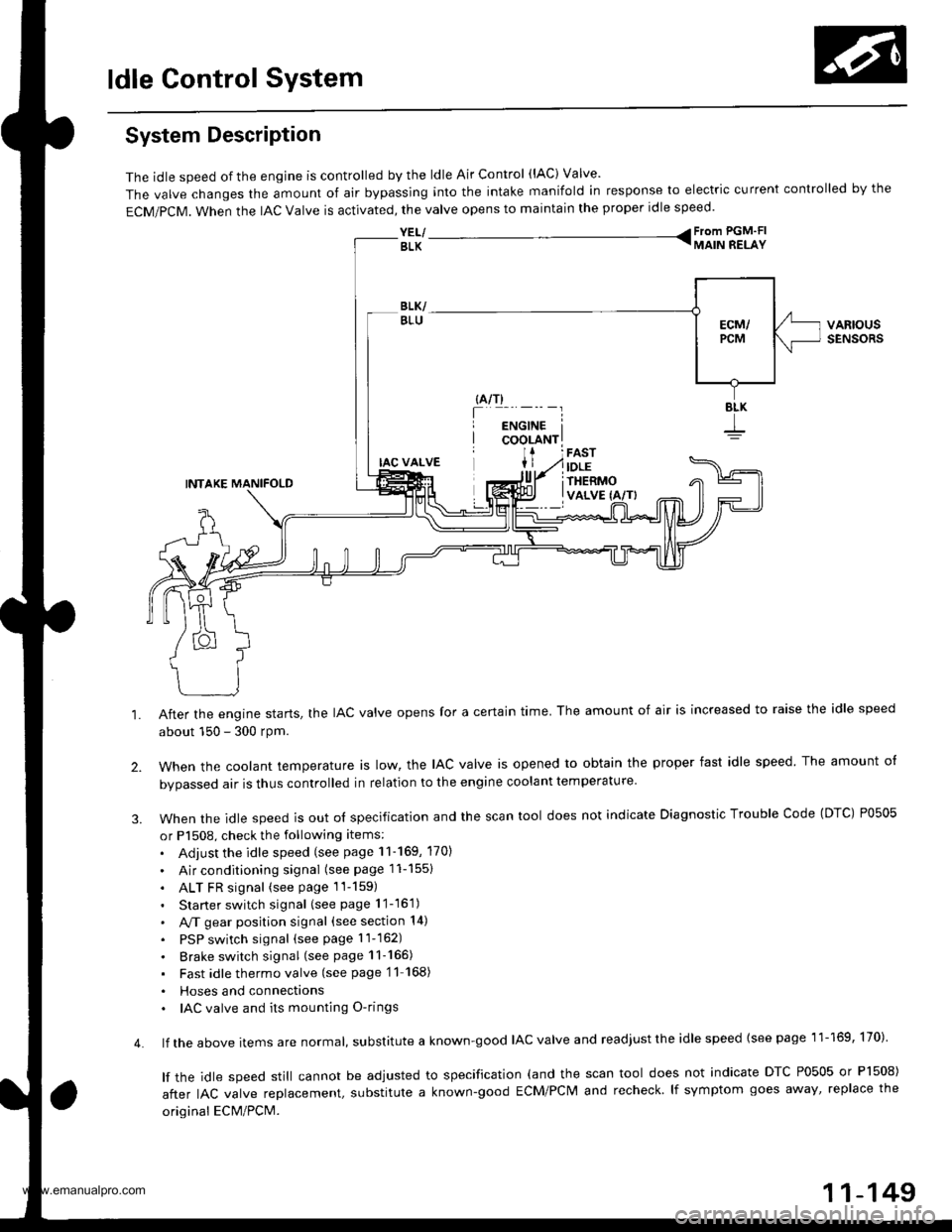
System Description
The idle speed of the engjne is controlled by the ldle Air Control (lAC) Valve'
The valve changes the amount of air bypassing into the intake manifold in response to electric current controlled by the
ECM/PCM. When the lAc valve is activated, the valve opens to maintain the proper idle speed.
YEL/ From PGM'FI
BLK TMAIN RELAY
VARIOUSSENSORS
4.
IAC VALVE
INTAKE MANIFOLD
After the engine starts, the IAC valve opens for a certain time. The amount of air is increased to raise the idle speed
about 150 - 300 rpm.
when the cootant temperature ts row, the lAc valve is opened to obtain the proper fast idle speed The amount o{
bvoassed air is thus controlled in relation to the engine coolant temperature
When the idle speed is out o{ specification and the scan tool does not indicate Diagnostic Trouble Code (DTC) P0505
or P1508, check the following items:
. Adjust the idle speed (see page 11-169, 170)
. Air conditioning signal (seepagell-1551
. ALT FR signal (see page 1l-159)
. Starter switch signal (see page 11-16'1)
. A,/T gear position signal (see section 14)
. PSP switch signal (seepagell-162)
. Brake switch signal (see page 11-165)
. Fast idlethermovalve (see page'11 168)
. Hoses and connecttons. IAC valve and its mounting O-rings
lf the above items are normat, suDslitute a known-good IAC valve and readjust the idle speed {see page 11-169, 170)
lf the idle speed still cannot be adjusted to specification (and the scan tool does not indicate DTC P0505 or Pl508)
after IAC valve reolacement, substitute a known-good ECM/PCM and recheck lf symptom goes away' replace the
original ECM/PCM.
11-149
www.emanualpro.com
Page 352 of 1395

ldle Control System
ldle Control System
I P0505 | The scan tool indicates Diagnostic T.ouble Code (DTCI PO5O5: ldlecontrol svstem mattunction.
NOTE: lf DTC P1508 is stored at the same time as DTC P0505, troubleshoot DTC P1508 first. then troubleshoot DTC p0505.
Possibls Cause
. IAC valve mechanical malfunction. Throttle body clogged port, improper adlustment. Intake manifold gasket leakaging. Intake air hose loose leakaging. Vacuum hose leakaging
a ECT sensor incorrect output. Throttle Position sensor incorrect output
Troubleshooting Flowchart
The MIL has been reDorted on.DTC P0505 is sto.ed.
Problem verificationi1. Start the engine. Hold theengine at 3,000 rpm with noload (in Park or neutral) untilthe radiator Ian comes on, thenlet it idle.2. With the scan tool, check thelollowing items.- Throttle position should beapprox. 10% with the throt-tle {ully closed.- Engine coolant temperature shorJld be 194 - 205'F(90 - 96"C).lf they are not within thespec., repair the faulty sen-sor circuit.3 Check the engine speed atidle with no-load conditions:headlights, blower fan. reardefogger, radiator lan, and airconditioner are not operaling,
Inte.mittent failure. syltem is OKat this time.ls it 750 {730)* i 50 rpm?
ls il 700 (680)' rpm or less?
{To page 11-151)(To page 1'l-151)
l:'99 - 00 models
www.emanualpro.com
Page 353 of 1395
(From page 11-150)
{From page 11-150}
THERMO VALVE(A/T onlyl
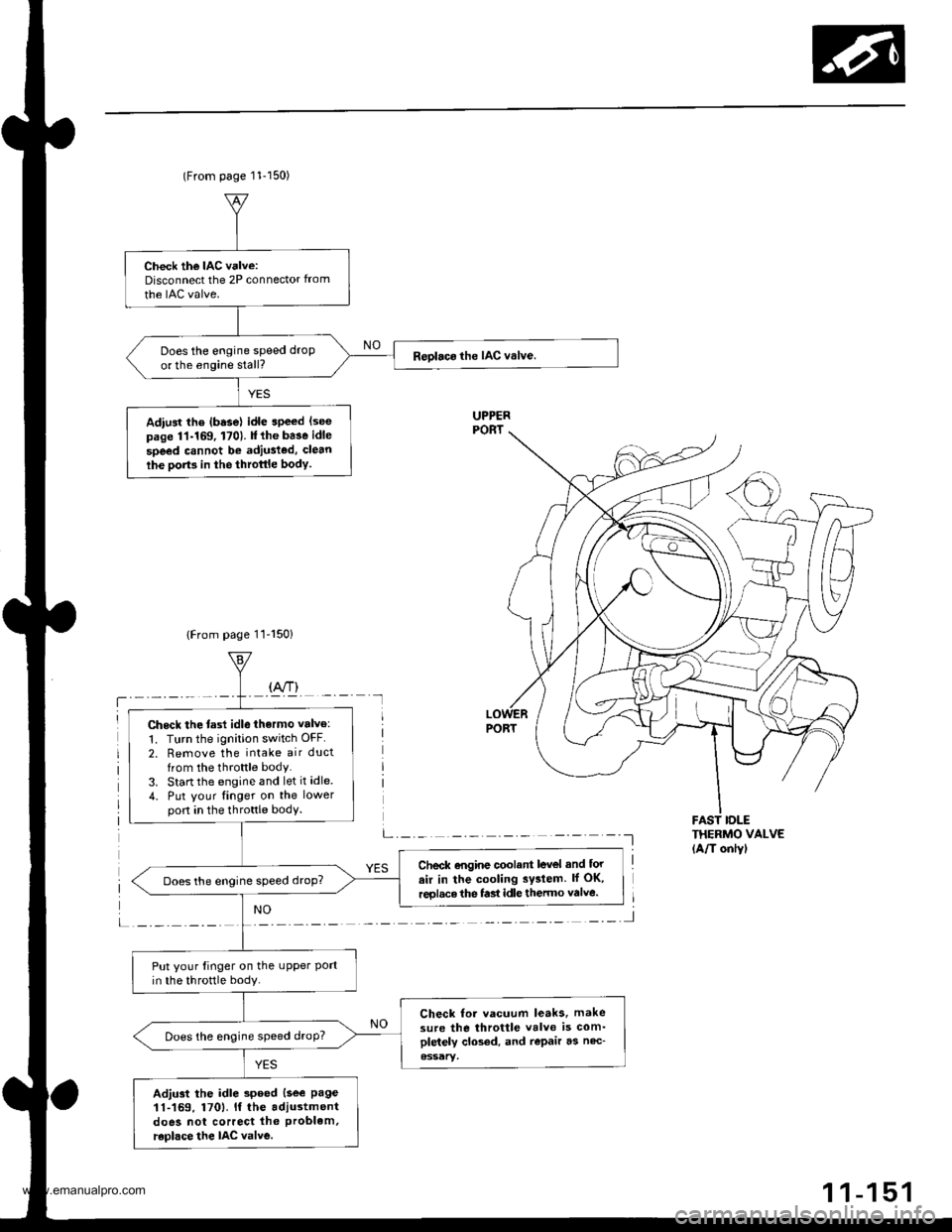
Check the IAC valve:Disconnect the 2P connector from
the IAC valve.
Does the engine speed droP
or the engine stall?
Adiust the (basel idl€ speed lseepage 11-169, 1t0). Itihe ba3e idle
speed cannot be adiust€d, clean
the Dorts in the throttle body.
UPPER
Check the tast idle lhermo valve:
1. Turn the ignition switch OFF.
2. Remove the intake air ductfrom the throttle body.3. Start the engine and let it idle.
4. Put your finger on the lowerpon in the throttle body.
Check engine cool.nt level and for
air in the cooling sy3lem. lf OK,
reolace the f.st idle thermo valve.Does the engine speed drop?
Put your Iinger on the uPPer Portin the throttle body.
Check for vacuum leaks, make
sure the throttle valve is com'pletely clo3ed. and repair as nec-Does the engine speed droP?
Adjust the idle spoed lsee Page11-169. 1701. lf the adiustmentdoes not correct lhe problem,
r.olace the IAC valve.
www.emanualpro.com
Page 354 of 1395
ldle Control System
ldle Air Control llAC) Valve
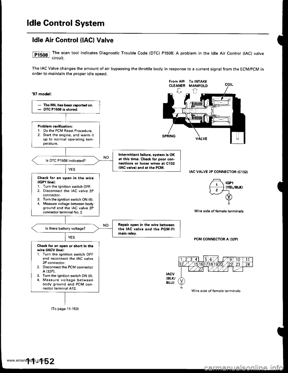
The scan tool indicates Diagnostic Trouble Code (DTC) Pl508: A probtem in the ldle Air Controt flAC) varvecircuit.
The IAC Valve changes the amount of air bypassing the throttle body in response to a current signal from the ECM/PCM inorder to maintain the proper idle speed.
37 model;
IAC VALVE 2P CONNECTOR {C132}
,f rcp'# IYEL/BI.(II2f-1-d)
Y
Wir€ side of female terminals
PCM CONNECTOR A I32PI
tacvIBLK/BLU)
From AIR To INTAKECLEANER MANIFOLD
Wire side of female terminals
The MIL has beon .eport€d on.OIC Pl508 is sto.ed.
Problem veiification:1. Do the PCM Reset Procedure.2. Start the engine, and warm itup to normal operating tem-perature.
Inte.mittent failure, systcm b OKat thi3 time. Check tor poo. con-nections or loose wircs at C132(lAC v.lvel and at the PCM.
ls DTC Pl508 indicated?
Check lor an open in the wir6{lGPl lins}:1. Turn the ignition switch OFF.2. Disconnect the IAC valve 2Pconnector.3. Turn the ignition switch ON {ll).4. Measure voltage between bodyground and the IAC valve 2Pconnector term inal No.2.
Repair open in the wire trctwoontha IAC v!lv6 and the PGM-Flmain relly.
Chock for an opan o. short in thowi.e (lACv linel:1. Turn the ignition switch OFFand reconnect the IAC valve2P connector.2. Disconnect the PCM conneclorA (32P).
3. Turn the ignition switch ON {ll).4, Measure voltage betweenbody ground and PCM con-nector terminal A12.
{To page 1l-153)
www.emanualpro.com
Page 356 of 1395
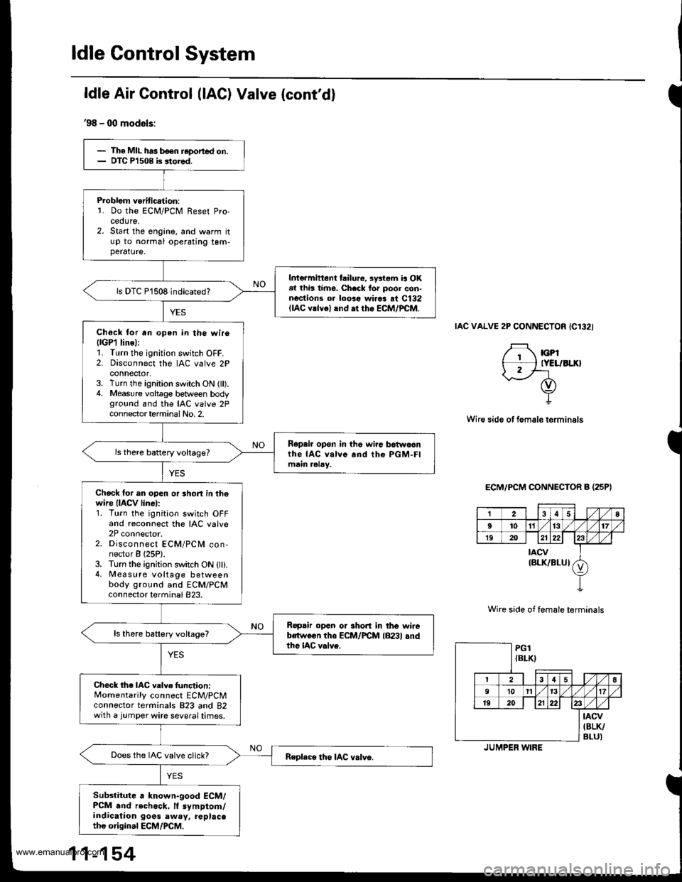
The MIL has boen r.ported on.DIC Pl 508 b 3tored.
Problem veritication:L Do the ECM/PCM Reset Pro-cedure.2. Start the engine, and warm itup to normal operating tem-perature.
Int€rmittent failure, systom is OKal lhis timo. Check lor poor con-nections or looro wirca at C132(lAc vrlvel and .t rho EcM/PcM.
ls DTC P1508 indicated?
Chock tor an open in the wir6llGPl linel:1. Turn the ignition switch OFF.2. Disconnect the IAC valve 2Pconnector,3. Turn the ignition switch ON (ll).4. Measure voltage between bodyground and the IAC valve 2Pcon nector termina I No, 2.
Repair opon in the wira botwoonthe IAC valve and tho PGM-FImain aalay.
Check tor an open or short in thewire (IACV linel:1. Turn the ignition switch OFFand reconnect the IAC valve2P connector.2. Disconnect ECM/PCM con-nector B {25P).3. Turn the ignition switch ON {ll}.4. Measure voltage betweenbody ground and ECM/PCMconnector terminal 823.
Ropair open or short in thg wirebetween tho ECM/FCM lB23l andthe IAC valve.
ls there battery voltage?
Check the IAC valve func,tion:Momentarily connect ECM/PCMconnector terminals 823 and 82with a jumper wire several times.
Does the IAC valve click?
Subslitute . known-good ECM/PCM .nd rechock. lf symptom/indication goes aw.y, replac.th€ original ECM/PCM.
ldle Air Control (lAC) Valve {cont'd}
'98 - 00 models:
IAC VALVE 2P CONNECTOR {C132I
F rcpt*l tYELrBLxlI2/'-- rf)
Y
Wire side ot fem.le terminals
ECM/PCM CONNECTOR B (25PI
Wire side of female torminals
258
9'to1l13t7
1920212223
tAcv(BLK/BLUIv
PG1{BLKI
12 | t3 4 58
910 111317
1920 | 121)22
tAcv(BLK/
BLU)JUMPER WIRE
www.emanualpro.com
Page 358 of 1395
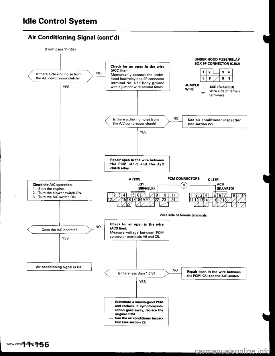
ldle Gontrol System
Air Conditioning Signal (cont'dl
(From page 11-'155)
JUMPERWIRE
UNOER.HOOD FUSE/RELAYBOX 9P CONNECTOR tqt52)
123I
56I
ACC IBLK/RWire side ofACC IBLK/REDIWire side of femaletermrnats
A t32PlPCM CONNECTORS C t3rp)
Wire side ol lemale terminals
Ch6ck for an open in th€ wire(ACC linel:Momentarily connect the under-hood fuse/relay box 9P connectorterminal No.5 to body groundwith a jumper wire several times.
ls there a cl;cking noise fromthe 4!/C compressor clutch?
ls there a clicking noise fromthe 4!/C compressor clutch?See air condiiioner inspection{see section 221.
Repai. op6n in the wire betwoenthe PcM (A17) and tho A/Cclutch relay.
Check the A/C operation:1. Start the engine.2. Turn the blower switch ON.3. Turn the A"/C switch ON.
Check for an open in the wire(ACS line):Measure voltage between PCMconnector terminals Ag and C5.
Does the A,/C operate?
Air conditioning signal is OK.
Repair open in the wire betweenthe PCM lCSl and the A/C awitch.ls there less than 1.0 V?
- Subqtitute a known-good FCM.nd r€ch6ck. lt 3ymptom/indi-cation goes awav, replece theoriginal rcM.- Soe th€ eir conditioner in3pec-tion (s6€ aec.tion 22).
www.emanualpro.com
Page 361 of 1395
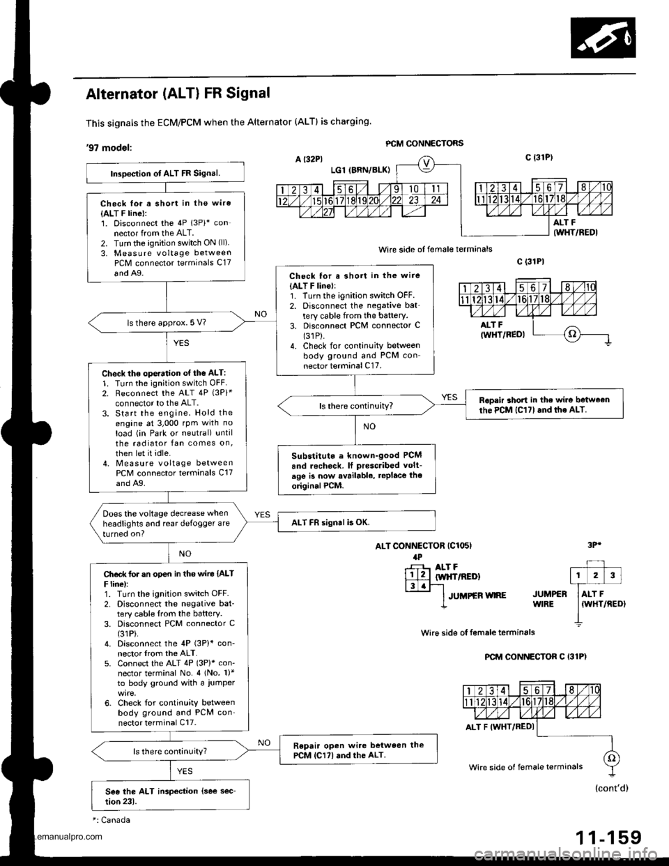
Alternator (ALT) FR Signal
This signals the ECM/PCM when the Alternator (ALTI is charging.
,97 modet: PCM GONNECTORS
wire side of female terminals
ALT CONNECTOR (C1O5I
lPr-F- ALT F
lll2llw|{frREDl|3.r-'l-
lruueen wne
c (31P|
wire side ol f€male terminals
PCM CONNECTOR C I31P)
3Pr
JUMPERWIRE
Inspection ot ALT FR Signal.
Check lor a short in the wire
{ALT F line}:1. Disconnect the 4P 13Pi* connector from the ALT.2. Turn the ignition switch ON (ll)
3, Measure voltage betweenPCM connector terminals C17
and A9.Check for a short in the wire(ALT F linel:1. Turn the ignition switch OFF.2. Disconnect the negative bat'tery cable from the battery.3. Disconnect PCM connector C(31P).
4. Check for continuity betweenbody ground and PCM connector terminal C17.
ls there approx. 5 V?
Check th€ ope.ation of the ALT:
1. Turn the ignition switch OFF2. Reconnect the ALT 4P {3Pi*connector to the ALT.3. Start the engine. Hold theengine at 3,000 rpm with no
load (in Park or neutral) untilthe radiator fan comes on,
then let it idle.4. Measure voltage betweenPCM connector terminals C17and A9.
Ropeir short in the wir6 betweonthe PCM lC17l and the ALT.
Substitut. a known-good PCM
and recheck. lf prescribed volt-
age is now availablo, replace the
originalPCM.
Does the voltage decrease when
headlights and rear defogger are
turned on?ALT FR signal b OK.
Ch€d( for an op€n in tho wire IALTF linel:1. Turn the ignition switch OFF.2. Disconnect the negative bat-tery cable lrom the battery.3. Disconnect PCM connector C(31P).
4. Disconnect the 4P (3P)* con-nector lrom the ALT.5. Connect the ALT 4P (3P)* con-nector terminal No. 4 (No. 1)*to body ground with a iumper
6. Check for continuity betweenbody ground and PCN4 con'nector terminal Cl7.
Repair open wi.e between thePCM lCl7l and the ALT.ls there continuity?
ALT F IWHT/REDI
Wire side of female terminals
1 1-159
www.emanualpro.com
Page 362 of 1395
![HONDA CR-V 2000 RD1-RD3 / 1.G Manual PDF
ldle Gontrol System
Alternator (ALT) FR Signal (contdl
98 - 00 modols:
ALT CONNECTOR (C1I}5I
4P
rH] Arr FllltwHr/REo)l3laF1
I JUMPER WIRE JUMPER+ WIRE
ECM/PCM CONNECTORS
Wire side of female termi HONDA CR-V 2000 RD1-RD3 / 1.G Manual PDF
ldle Gontrol System
Alternator (ALT) FR Signal (contdl
98 - 00 modols:
ALT CONNECTOR (C1I}5I
4P
rH] Arr FllltwHr/REo)l3laF1
I JUMPER WIRE JUMPER+ WIRE
ECM/PCM CONNECTORS
Wire side of female termi](/img/13/5778/w960_5778-361.png)
ldle Gontrol System
Alternator (ALT) FR Signal (cont'dl
'98 - 00 modols:
ALT CONNECTOR (C1I}5I
4P
rH] Arr Fl'l'ltwHr/REo)l3laF1
I JUMPER WIRE JUMPER+ WIRE
ECM/PCM CONNECTORS
Wire side of female terminals
ECM/PCM CONNECTOR C {31PI
Wire side of female terminals
Wire side of female terminals
ECM/PCM CONNECTOR C {31P}
": Canada
1 1-160
B (25P)
Insp€ction of ALT FR Signsl.
Check fo. a shon in th. wire {ALTF linel:1. Disconn6ct the 4P (3P)* con-nector from the ALT.2. Turn the ignition switch ON {ll).3. Measure voltage between ECM/PCM connector terminals C5and 820.Ch€ck for a sho.t in iho wirc lAlTF lino):1. Turn the ignition switch OFF.2. Disconnecl the negative bat,tery cable from the battery.3. Disconnect ECM,PCM connec-torC (31P).
4. Check for continuity betwoenbody ground and ECM/PCMconnector terminal c5.
ls there approx. 5 V7
Check the opcration of the ALT:1. Turn the ignitioo switch OFF.2. Reconnect rhe ALT 4P (3P)*connector to the ALT.3. Start the engine. Hold theengine at 3,000 rpm with noload (in Park or neutral) untilthe radiator lan comes on,then let it idle.4. Measure voltage between ECM/PCM connector terminals C5and 820.
Roprir lhort in tho wirc bstweentho ECM/PCM {Csl and the ALT.
Substitut. r known-good ECM/PCM and roch.ck. It Droscrib.dvoltage b now lvrilabls, .eplaccth. o.igin!l ECM/PCM.
Does the voltage decrease whenheadlights and rear defogger areturned on?ALT FR 3ignol is OK,
Chock lor an opon in tha wire (ALTF linel:1. Turn the ignition switch OFF.2. Disconnect the negative bat-tery cable from the battery.3. Disconnect ECM/PCM con-nector C (31P).4. Disconnect the 4P 13P)* con,nector from the ALT.5. Connect the ALT 4P {3P)* con-nector terminal No. 4 1No. 1)*to body ground with a jumper
6. Check for continuity betwe€nbody ground and ECM/PCMconnector terminal C5.
Rsprir opan wiro batw.en thoECM/PCM lcsl .nd th. ALT.ls there continuity?
AI.T F IWHT/REDI
ALT F {WHT/REDI
Wire side ot Iemale terminals
www.emanualpro.com
Page 363 of 1395
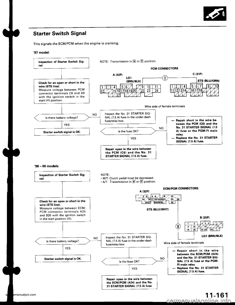
Starter Switch Signal
This signals the ECM/PCM when the engine is cranking.
'97 model:
A {32P}
'98 - 00 models:
Transmission in E or E position.
LGl(BBN/BLK)
PCM CONNECTORS
Wire side of female terminals
ECM/PCM CONI{ECTORS
STS (BLU/ORNI
c t31P)
NOTE:. M/T: Clutch pedal must be depressed.. A/T: Transmission in E orE position
Check for an opan ot short in the
wire (STS linel:Measure voltage between PCM
connector terminals C6 and Ag
with the ignition switch in the
start (lll) position.
lnspect the No. 31 STARTER SIG-
NAL (7.5 A)Illse in the under'dashls there battery voltage?- Reoair short in the wire be-
tween the PCM lc6l and th.No. 31 STARTER SIGNAL 17 5A) tuse ot the PGM-FI main
reray.- Reolace the No. 31 STARTERSIGNAL t7.5 Altu.e.
Starter swiich signal i3 OK.
Repair opon in the wire betweonrh6 PCM lc6l and the No 31
STARTER SIGNAL 17.5 A)fuse.
A (32P)
Wire side oI female terminals
Check tor an open or short in thewir€ (STS line):Measure voltage between ECM/
PCM connector terminals A24
and 820 with the ignition switchin the start position (lll).
Inspect the No. 31 STARTER SIGNAL (7.5 A){use in the under-dashls there battery voltage?
- Reoair shorl in the wire
betwe€n the ECM/PCM lA2,fland the No, 31 STARTER SIG-NAL t7.5 Al tu3€ ot the PGM'Fl main rclay.- Repl.c. tho No. 31 STARTERSIGNAL 17.5 Al fu3e.
Starter switch 3ignal is OK.
Repair opon in tho wire between
the ECM/PCM {A241 and the No
31 STARTER SIGNAL (7.5 A) tu3e
1 1-161
www.emanualpro.com