Reverse HONDA CR-V 2000 RD1-RD3 / 1.G Manual Online
[x] Cancel search | Manufacturer: HONDA, Model Year: 2000, Model line: CR-V, Model: HONDA CR-V 2000 RD1-RD3 / 1.GPages: 1395, PDF Size: 35.62 MB
Page 916 of 1395
Front Damper
Reassembly
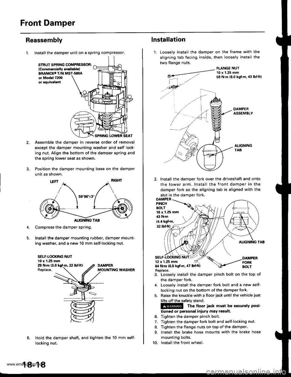
1. Install the damper unit on a spring compressor.
STRUT SPflNG COMPBESSOR:lcomm.rcillly .vrilrble)BRANICKC T/N MST.sEOAor Mod.l 7200or oquivtla
SPRING LOWER SEAT
Assemble the damper in reverse order of removal
except the damper mounting washer and self lock-
ing nut. Align the bottom of the damper spring and
the spring lower seat as shown.
Position the damper mounting base on the damper
unit as shown.
Compress the damper spring,
Install the damper mounting rubber, damper mount-
ing washer, and a new 10 mm self-locking nut.
SELF-LOCKING NUT10 x 1.25 mmZt N.m 13.0 kgf.m, 22 lbf.ft)Replace.
Hold the damper shaft, and tighten the
locking nut.
DAMPERMOUNfING WASHER
18-18
10 mm self-
1.
lnstallation
Loosely install the
aligning tab facing
two flange nuts.
damper on the frame with
inside, then loosely install
FLANGE NUT
the
tne
-__---a-"- 10 x 1.25 mmg*- 59 N.m {5.0 kgt m, 43 tbf.ftl
| -,./.46- --...
./ -4 A-
DAMPERASSEMBLY
ALIGNINGTAB
2, Install the damper fork over the driveshaft and onto
the lower arm. Install the front damper in the
damper fork so the aligning tab is aligned with the
slot in the damDer fork,
3. Loosely install the damper pinch bolt on the top of
the damper fork.
4. Looselv install the damper fork bolt and a new self-
locking nut on the bottom of the damper fork.
5. Raise the knuckle with a floor iack until the vehicle just
lifts off the safetv stand.
The lloor iack must b€ socurely posi-
tioned or personal iniury may result.
6. Tighten the damper pinch bolt.
7. Tighten the damper fork bolt and self-locking nut.
8. Tighten the flange nuts on top of the damper.
9. Install the brake hose mounts with the brake hose
mounting bolts.
10. Installthe front wheel.
10 x 1.25 mmil3 l+m
{4.4 kgf'm,
Replace.
www.emanualpro.com
Page 920 of 1395
Rear Suspension
Hub Bearing Unit Replacement (cont'd)
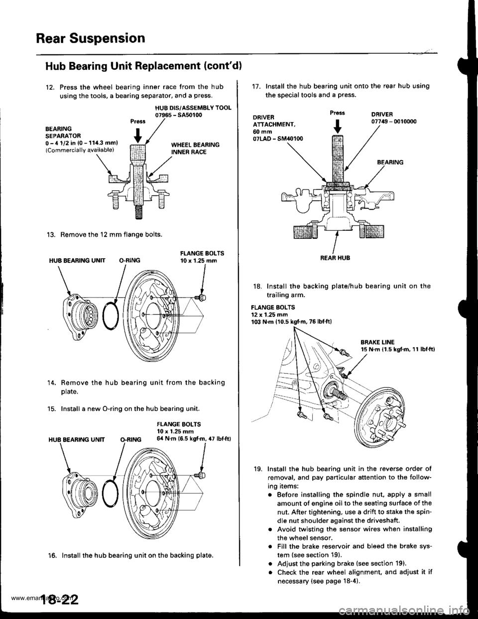
12, Press the wheel bearing inner race from the hub
using the tools, a bearing separator, and a press.
HUB DIS/ASSEMBLY TOOL07965 - SA50100
BEARINGSEPARATOR0 -,t 1/2 in {0 - 11i1.3 mml(Commercially qvailable)
13. Remove the 12 mm flange bolts.
HUB BEARING UN]T O.RING
14. Remove the hub bearing unit from the backing
plate.
15. Install a new O-ring on the hub bearing unit.
FLANGE BOLTS10 x 1.25 mm64 N.m (6.5 kgf.m, 47 lbf.ftl
16. Install the hub bearing unit on the backing plate.
18-22
't7.Install the hub bearing unit onto the rear hub using
the special tools and a press.
DRIVERATTACHMENT,60 mm07LAO - SM40100
Prcss
+
DRIVER07749 - 0010000
BEARING
18. Install the backing plate/hub
trailing arm.
FLANGE BOLTS12 x 1.25 mm103 N.m 110.5 kgf'm,75lbfft)
bearing unit on the
19. Install the hub bearing unit in the reverse order of
removal, and pay particular attention to the follow-
ing items:
. Before installing the spindle nut, apply a small
amount of engine oil to the seating surface of the
nut, After tightening, use a drift to stake the spin-
dle nut shoulder against the driveshaft.
. Avoid twisting the sensor wires when installing
the wheel sensor,
. Fill the brake reservoir and bleed the brake sys-
tem {see section 19).
. Adjust the parking brake (see section 191.
. Check the rear wheel alignment, and adjust it if
necessary (see page 18-4).
REAR HUB
www.emanualpro.com
Page 923 of 1395
Reassembly
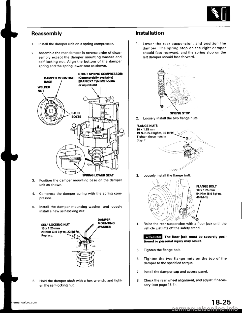
1.Install the damper unit on a spring compressor,
Assemble the rear damper in reverse order of disas-
sembly except the damper mounting washer and
self-locking nut. Align the bottom of the damper
spring and the spring lower seat as shown.
2.
DAMPER MOUNNNG
STRUT SPBING COMPRESSOR:(Commorcislly !v.ilablelBRANICKC T/N MST.s8OA
3.Position the damper mounting base on the damper
unit as shown.
Compress the damper spring with the spring com-
pressor.
Install the damper mounting washer, and loosely
install a new self-locking nut.
SELF.LOCKING NUT10 x 1.25 mm29 N.m (3.0
Replace.
Hold the damper shaft with a hex wrench, and tight-
en the self-locking nut.
1.
lnstallation
Lower the rear suspenston,
damper. The spring stop on
should face rearward, and the
left damper should face forward.
and position the
the right damper
sprang stop on the
SPRING STOP
2. Loosely install the two flange nuts.
FLANGE NUTS10 x 1.25 mm . .:{9 N.m 15.0 kgf.m, 36 lbtft}- :',,-rigf't"n if'"""_nrr. in ----.-*
qla^ 7Step 7.
3. Loosely install the flange bolt.
FLANGE EOLT10 x 1.25 mm54 N.m 15.5 kgt.m,40 tbI.ft)
6.
7.
8.
Raise the rear suspension with a floor jack until the
vehicle just lifts off the safety stand.
@ The floor iack must be securely posi-
iioned or personal iniury may result.
Tighten the flange bolt.
Tighten the two flange nuts on the top of the
damper to the specified torque.
Install the damper cap and access panel.
Check the rear wheel alignment. and adjust if neces-
sary (see page 18-4).
18-25
www.emanualpro.com
Page 937 of 1395

Master Cylinder/Brake Booster
Removal/lnstallation
1, Disconnect the brake fluid level switch connectors.
2. Remove the reservoir cap from the master cylinder.
3. Remove the brake fluid from the master cvlinder
reservoir with a syringe.
4. Disconnect the brake lines from the master cylinder.
To prevent spills, cover the line joints with rags or
shop towels.
5. Remove the master cylinder mounting nuts and
wasners.
6. Remove the master cylinder from the brake booster.
CAUTION: Be careful not to bend or damage the
brake lines when removing the master cylinder.
Do not spill brake fluid on the vehicle; it may dam.
age the paint; it brake fluid does cont.ct the paint,
wash it oft immediately with water.
7. Disconnect the vacuum hose from the brake booster.
8. Remove the cotter pin and clevis pin from the clevis.
Do not disconnect the clevis by removing it from
the operating rod of the brake booster. lf the clevis
is loosened, adjust the pushrod length before
installing the brake booster (see page 19-15).
To Front Caliper (Without ABS)
\\
15 N.m {1.5 kgtm, vAcuuM HosE
r r rbf.ft) |
/ | BRAKE FLUTD LEvEL
/l /
swrrcHcoNNEcroRs
/ I I I COTTER PIN
I I / neotace
l,/-- ro Rear wheet cylinders / | I
h ./-''' /. I I IYli //*s (.S
I /r:
9. Remove the four booster mounting nuts.'10. Pull the brake booster forward until the clevis is
clear of the bulkhead.
11. Remove the brake booster from the enqine com-
panment.
12. Install the brake booster and master cylinder in the
reverse order of removal, and note these items:
. When connecting the brake lines, make sure that
there is no interference between the brake lines
and other parts.
. Be careful not to bend or damage the brake lines
when installing the master cylinder.
. lf replacing the master cylinder or brake booster,
check and adjust the pushrod clearance before
installing the master cylinder (see page 19-14).
Fill the master cylinder reservoir, and bleed the
brake system (see page 19-7).
After installation, check the brake pedal height and
brake pedal free play (see page 19-5), and adjust if
necessary.
13 N.m 11.3 kg{.m,I rbf.ft)
13.
14.
To Master Cylinder(Without ABS)To Modulator Unit(with ABs)@-\
\
^ To Front Caliper
9i\.
-#qCLEVIS PIN
):-,/
PROPORTIONING CONTROL VALVE
MASTER CYLINDER
15 N.m (1.5 kgf.m, 11 lbl.ftl
BRAXE BOOSTER
www.emanualpro.com
Page 944 of 1395
Rear Drum Brakes
Brake Shoes Replacement (cont'd)
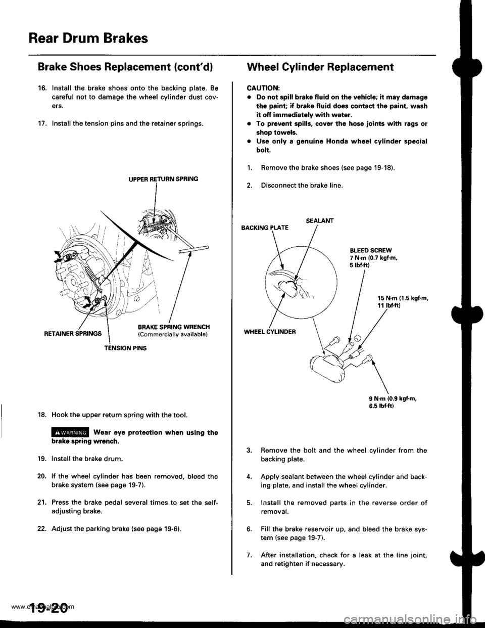
16. Install the brake shoes onto the backing plate. Be
careful not to damage the wheel cylinder dust cov-
ers.
17. Install the tension pins and the retainer springs.
18. Hook the upper return spring with the tool.
@ wsar eye proieclion whon using tho
brtko spring wronch.
lnstallthe brake drum.
lf the wheel cylinder has been removed, bleed the
brake system (see page 19-7).
Press the brake pedal several times to set the self-
adjusting brake.
Adjust the parking brako (see page 19-6).
19.
20.
21.
UPPER RETURN SPRING
TENSION PINS
19-20
7.
SEALANT
Wheel Cylinder Replacement
CAUTION:
. Do not spill brake fluid on th6 vehicle; it may damage
the paint; if brako fluid doos contact tho paint, wash
it off immedialely whh water.
. To pr6v6ni 3pills, cov6r th6 hose ioinls with rags ol
shop lowels,
. Use only a genuine Honda whoel cylinder spocial
bolt.
Remove the brake shoes {see page '19-18).
Disconnect the brake line,
BACKING PLATE
1.
15 N,m 11.5 kgt m,11 tbf.ftl
WHEEL CYLINDER
9 N.m 10,9 kgf'm.6.5 rbtft)
Remove the bolt and the wheel cylinder from the
backing plate.
Apply sealant between the wheel cylinder and back-
ing plate, and install the wheel cylinder.
Install the removed parts in the reverse order of
removal.
Fill the brake reservoir up. and bleed the brake sys-
tem {see page 19-7).
After installation. check for a leak at the line joint.
and retighten if necessary.
www.emanualpro.com
Page 947 of 1395
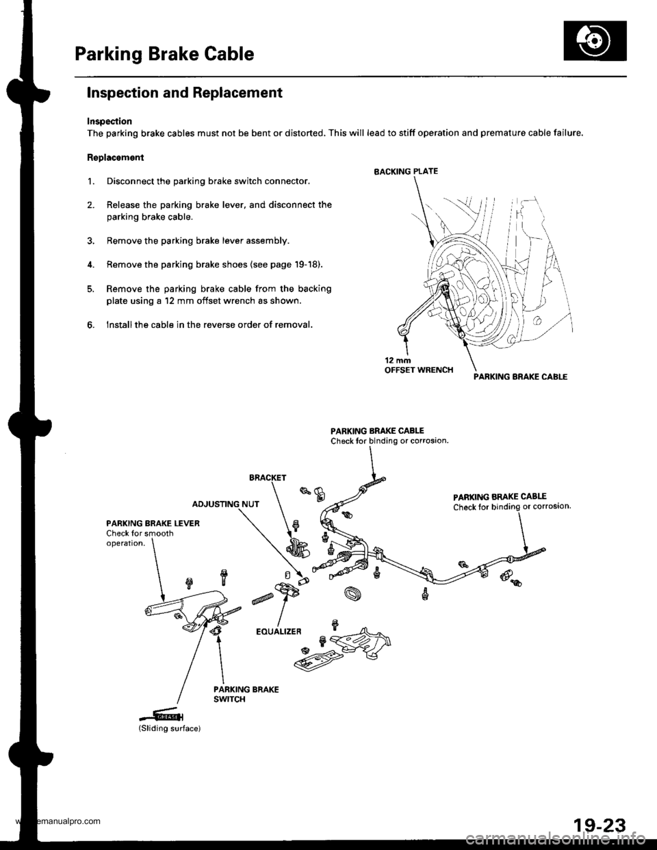
Parking Brake Cable
Inspection and Replacement
Inspection
The parking brake cables must not be bent or distorted, This will lead to stiff operation and premature cable failure.
Replacoment
l. Disconnect the parking brake switch connector.
2. Release the parking brake lever. and disconnect the
parking brake cable.
3, Bemove the parking brake lever assembly.
4. Remove the parking brake shoes {see page '19-18).
5. Remove the parking brake cable from the backing
plate using a '12 mm offset wrench as shown.
6. Installthe cable in the reverse order of removal.
BRACKET
PABKING ARAKE CABLE
Check toror corroston,
PARKING BRAKE LEVERCheck for smoothoperation,
d
,"u/n*UM
-6l(Sliding surface)
PARKING BRAKE CABI-E
19-23
www.emanualpro.com
Page 980 of 1395
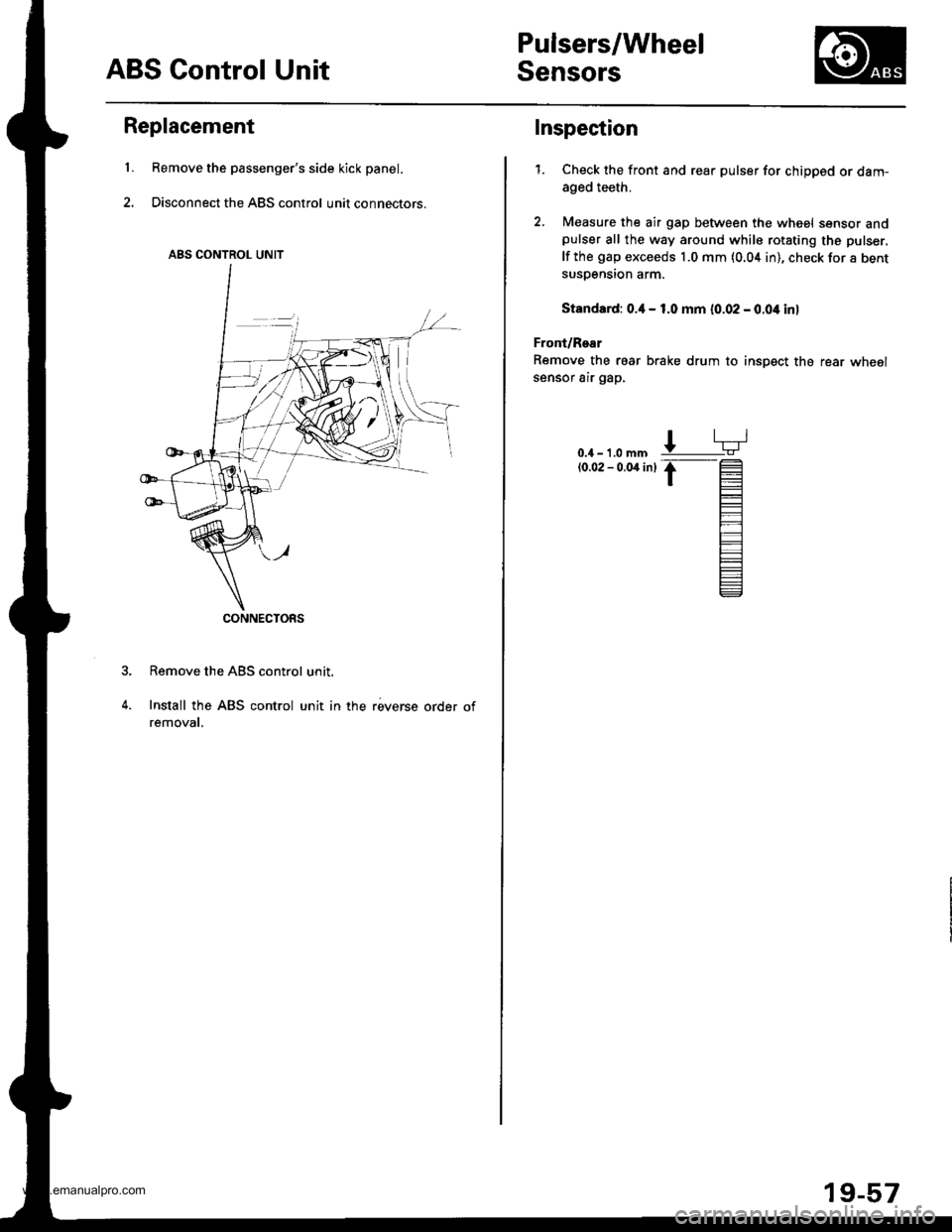
ABS Control Unit
Pulsers/Wheel
Sensors
Replacement
Remove the passenger's side kick panel.
Disconnect the ABS control unit connectors.
Remove the ABS control unit.
Install the ABS control unit in the reverse order ofremovat.
ABS CONTROL UNIT
CONNECTORS
L
Inspection
1.Check the front and rear pulser for chipped or dam-
aged teeth.
Measure the air gap between the wheel sensor andpulser all the way around while rotating the pulser.
lf the gap exceeds 1.0 mm (0.04 in), check for a bentsusDension arm.
Standard: o.il - 1.0 mm 10.02 - 0.04 inl
Front/Rear
Remove the rear brake drum to insDect the rear wheolsensor air gap,
0.4 - 1.0 mm(0.02 - 0.04 inl
19-57
www.emanualpro.com
Page 988 of 1395
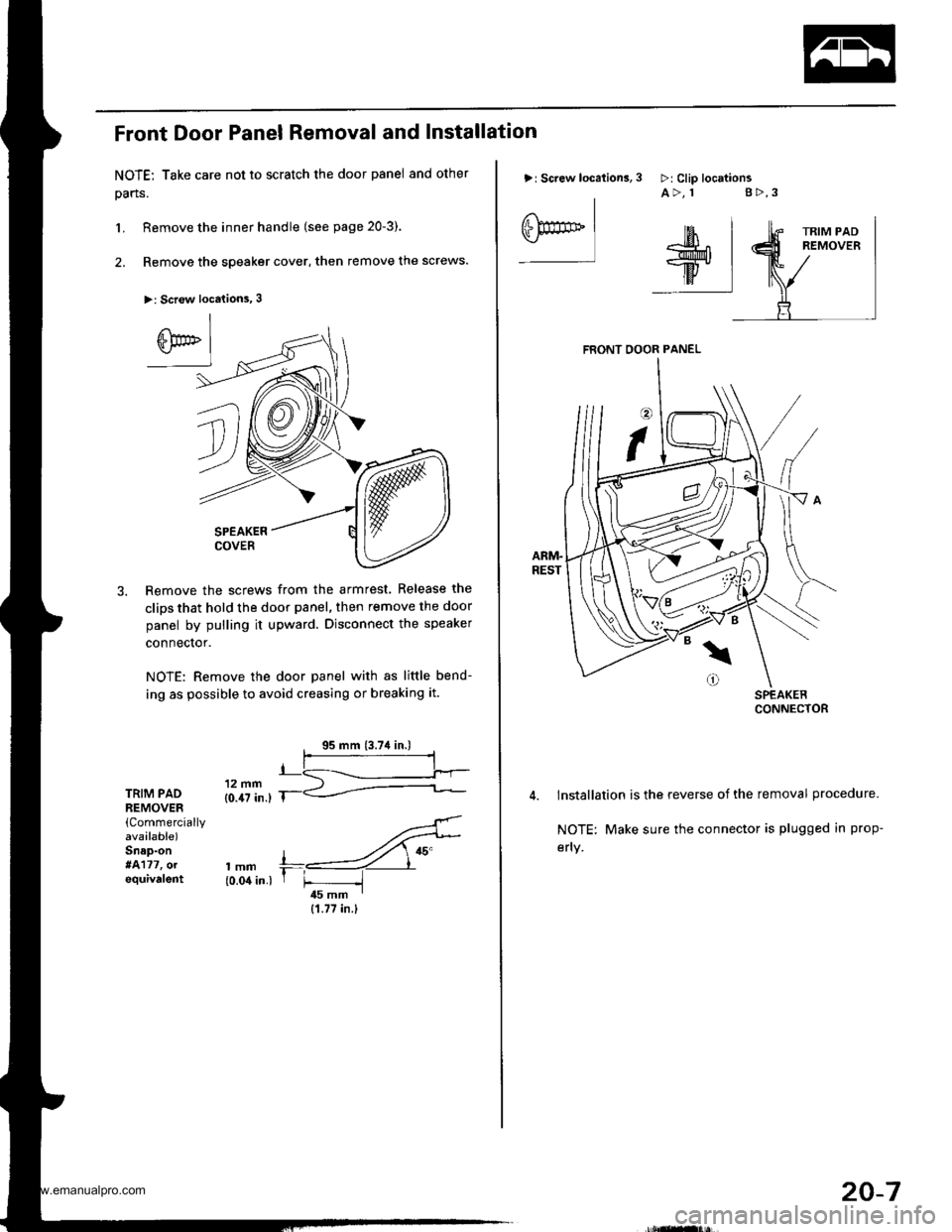
Front Door Panel Removal and Installation
NOTE: Take care not to scratch the door panel and other
pans.
L Remove the inner handle (see page 20-3).
2. Remove the speaker cover, then remove the screws.
>: Scr€w locations, 3
SPEAKERCOVER
Remove the screws from the armrest. Release the
clips that hold the door panel, then remove the door
panel by pulling it upward. Disconnect the speaker
connector.
NOTE: Remove the door panel with as little bend-
ing as possible to avoid creasing or breaking it.
TRIM PADREMOVER(Commercially
avaalable)Snap-on*4177, olequivalent
'..4'
,mm +,----ZY"{0.04 in.) r F -i45 mm I
{1.77 in.}
>: Screw location3,
I
eF** Iffil$;^r*l-w.
ttv IilF:I
3 >:Clip locttionsA>, 1 g>,3
FRONT OOOR PANEL
lnstallation is the reverse of the removal procedure.
NOTE: Make sure the connector is plugged in prop-
efly.
20-7
www.emanualpro.com
Page 989 of 1395
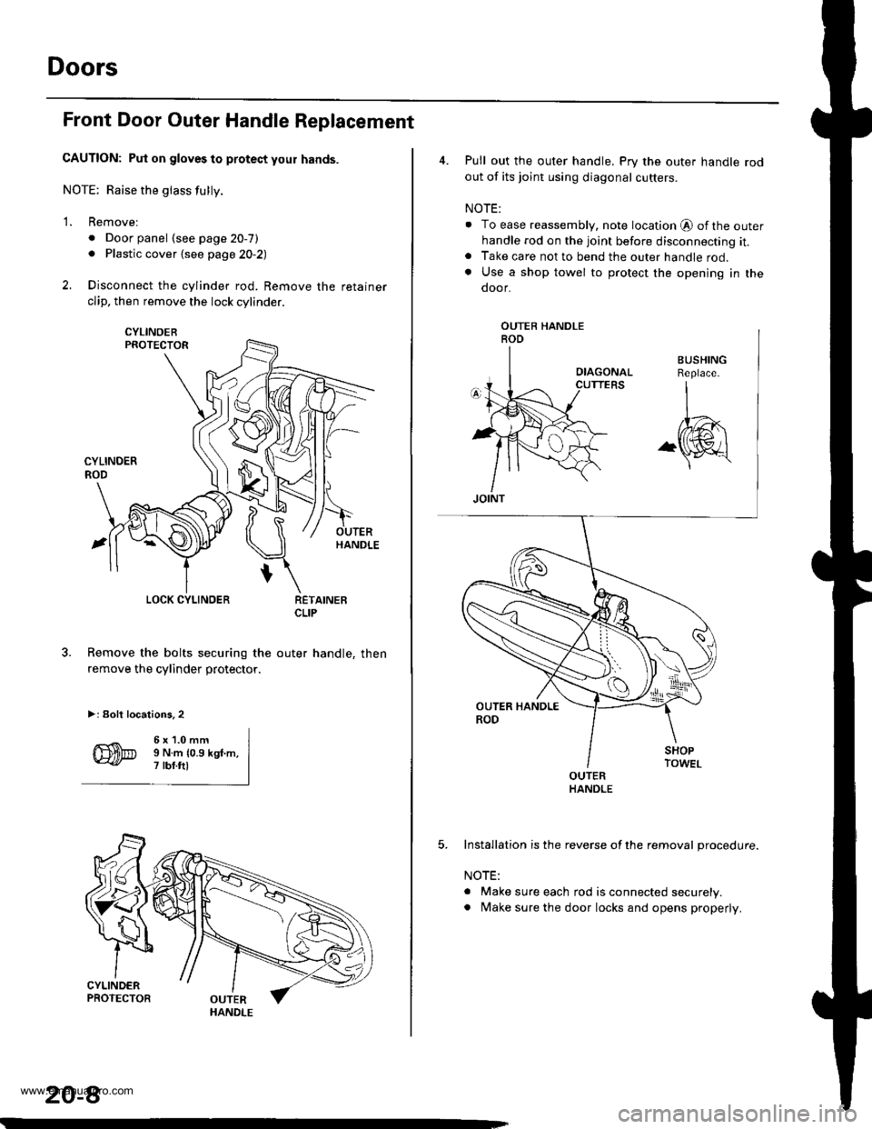
Doors
Front Door Outer Handle Replacement
CAUTION: Put on gloves to protect your hands.
NOTE; Raise the glass fully.
2.
1.Removel
. Door panel (see page 20-7). Plastic cover {see page 2O-2)
Disconnect the cylinder rod. Remove the retainer
clip, then remove the lock cylinder.
5.
6 x'1.0 mmI N.m {0.9 kgt.m,7 rbf.ftl
LOCK CYLINDER
Remove the bolts securing the
remove the cylinder protector.
>: Eolt locations,2
RETAINEBCLIP
outer handle, then
HANDLE
20-8
4. Pull out the outer handle, Pry the outer handle rod
out of its joint using diagonal cutters.
NOTE:
. To ease reassembly, note location @ ofthe outerhandle rod on the joint before disconnecting it.. Take care not to bend the outer handle rod.. Use a shop towel to protect the opening in the
door.
OUTEBHANDLE
5. Installation is the reverse of the removal procedure.
NOTE:
. Make sure each rod is connected securely.. Make sure the door locks and opens properly.
www.emanualpro.com
Page 990 of 1395
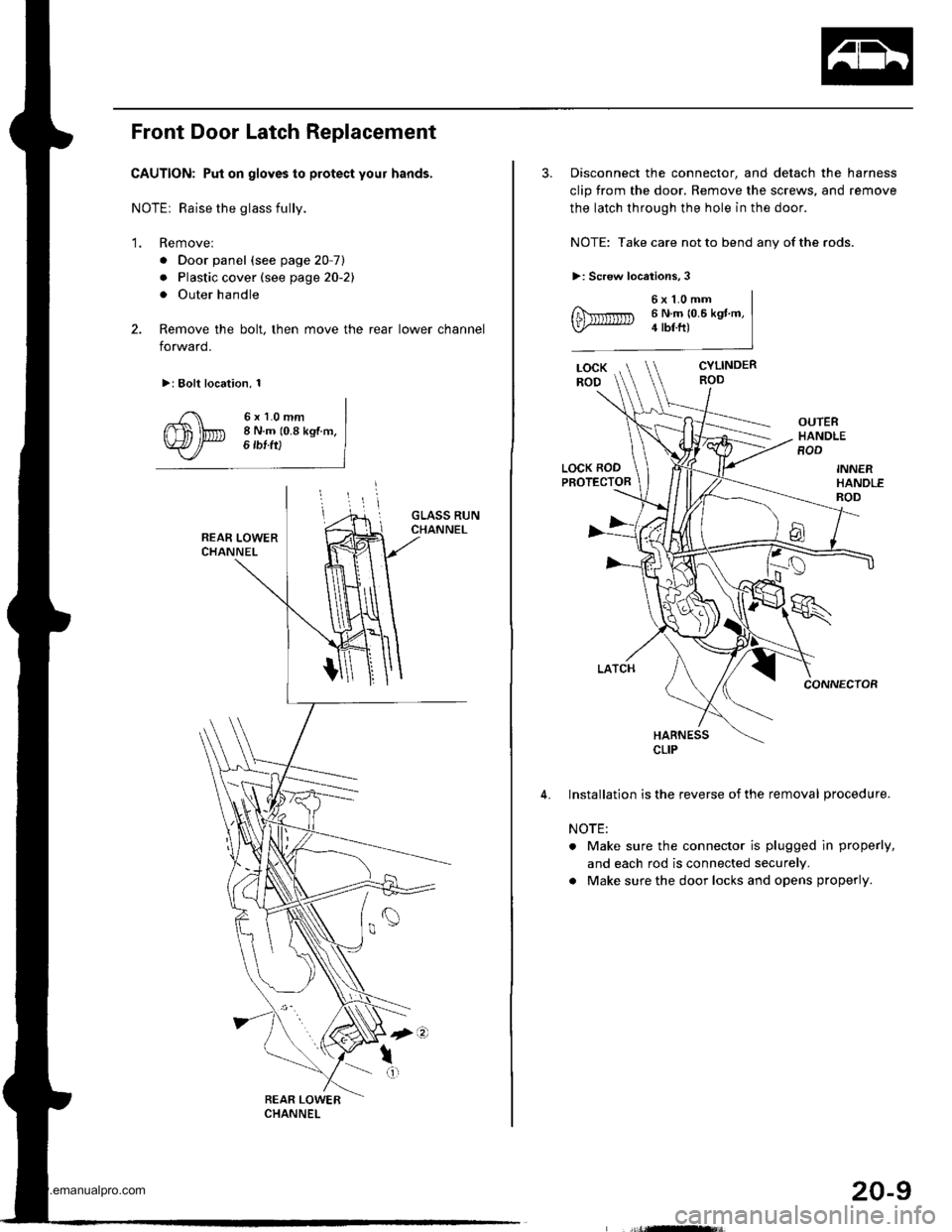
Front Door Latch Replacement
CAUTION: Put on gloves to protect your hands,
NOTEr Raise the glass fully.
'1. Remove:
. Door panel (see page 20-7)
. Plastic cover (see page 20-21
. Outer handle
2. Remove the bolt, then move the rear lower channel
forward.
>: Bolt location, 1
6xl.0mm8 N.m (0.8 kgf m,6 tbf ft)
3. Disconnect the connector, and detach the harness
clip from the door. Remove the screws, and remove
the latch through the hole in the door.
NOTE: Take care not to bend any of the rods.
>: Screw locations,3
6x1.0mm6 N.m 10.6 kgt m,4 tbf.ft)
CYLINDERROD
OUTERHANDLEROD
LOCK RODPROTECTOR
CONNECTOR
HARNESS
Installation is the reverse of the removal procedure.
NOTE:
. Make sure the connector is plugged in properly,
and each rod is connected securely.
a Make sure the door locks and opens properly.
CLIP
20-9
www.emanualpro.com