body HONDA CR-V 2000 RD1-RD3 / 1.G Manual Online
[x] Cancel search | Manufacturer: HONDA, Model Year: 2000, Model line: CR-V, Model: HONDA CR-V 2000 RD1-RD3 / 1.GPages: 1395, PDF Size: 35.62 MB
Page 422 of 1395
Emission Control System
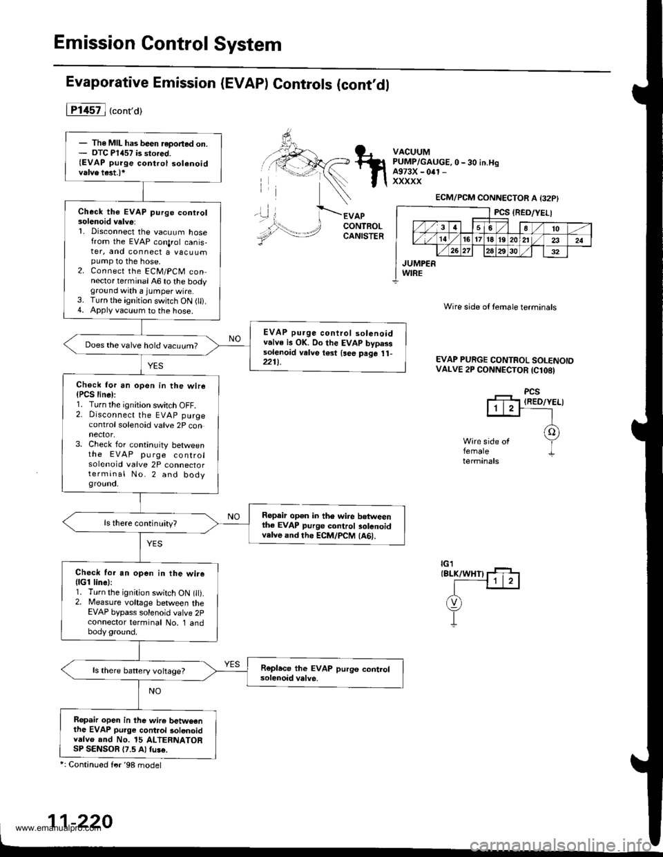
Evaporative Emission (EVAP) Controls (cont,dl
iTl457l ("ont'or
APCONTROLCANISTER
Ropair op€n in th6 wire betweenthe EVAP purge control 3olenoidvelve and ths ECM/PCM (A61.
VACUUMPUMP/GAUGE, O-30 iN.HgA973X - 0rl -
xxxxx
'\)
Wire side of lemale terminals
EVAP PURGE CONTROL SOI.ENOIDVALVE 2P CONNECTOR (Cl08)
PCSIRED/YELI
femaletermanals
ECM/PCM CONNECTOR A {32P}
PCS (RED/YELI
,/3 458/'t0
,,/ 14 ,/'t61718l92024
,/ 262930
JUMPERWIRE
- The MIL has been reported on.- DTC P1457 is stored.{EVAP purge control solenoidvalve test.l*
Check the EVAP purge conrrol30lenoid velve:L Disconnect the vacuum hosefrom the EVAP conlrol canis,ter, and connect a vacuumpump to the hose.2. Connect the ECM/PCM connector terminal A6 to the bodyground with a jumper wire.3. Turn the ignition switch ON (tl).4. Apply vacuum to the hose.
EVAP purge control solenoidvalve is OK. Oo the EVAP bypasssolenoid valve t€3t {see psge 1l-221t.
Does the valve hold vacuum?
Check for an open in the wire(PCS line):1. Turn the ignition switch OFF.2. Disconnect the EVAP purgecontrol solenoid valve 2P connector,3. Check for continuity betweenthe EVAP pu rge controlsolenoid valve 2P connectorterminal No.2 and bodygrouno,
ls there continuity?
Check for an open in the wire(lGl line):1. Turn the ignition switch ON t).2. Measure voltage between theEVAP bypass solenoid valve 2pcoonector terminal No. 1 andbody ground.
ls there battery voltage?
Repah open in lhe wir6 betwoenthe EVAP pu.ge cont.ol solonoidvdlvo and No. 15 ALTERNATORSP SENSOR {7.5 Al fu!€.
*: Continued frr '98 model
1-220
www.emanualpro.com
Page 423 of 1395
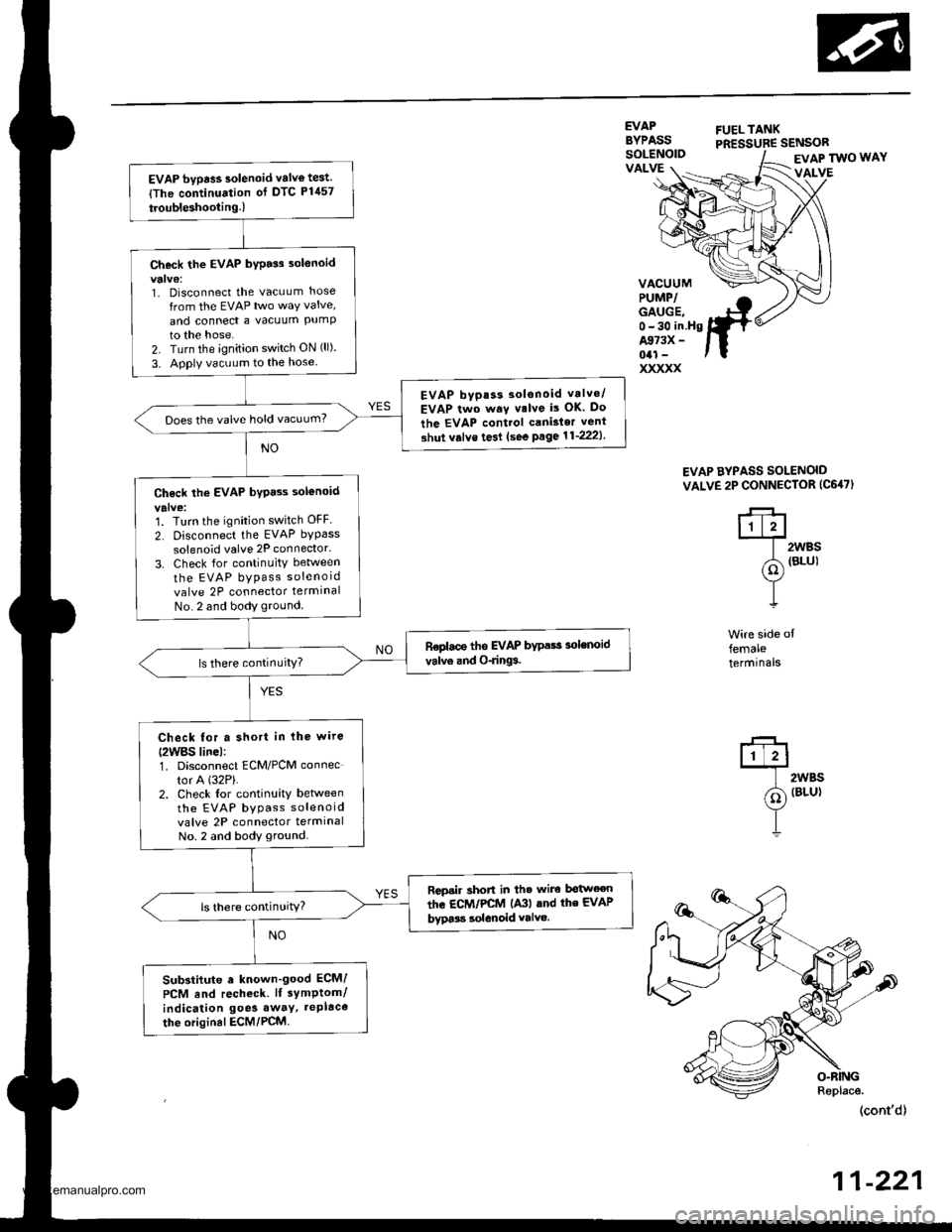
EVAP bypass solenoid valv€ test.
{The continuation of DTC P1457
troubleshooting.l
Check the EVAP bypass 3olenoid
1. Disconnect the vacuLlm hose
from the EVAP two way valve,
and conned a vacuum PUmPto the hose.2. Turn the ignition switch ON (ll).
3. Apply vacuum to the hose
EVAP bvpas3 30lsnoid vrlvo/
EVAP two way v.lve is OK. Do
the EVAP control canisler vent
3hut v.lve te3l (see Psge11'2221.
Does the valve hold vacuum?
Ch6ck the EVAP byp.ss solenoid
'1. Turn the ignition switch OFF
2. Disconnect the EVAP bypass
solenoid valve 2P connector.
3. Check {or continuity between
the EVAP bypass soleno id
valve 2P connector termlnal
No. 2 and body ground
ReDlace the EVAP bypass 3olenoid
valve and O-rings.
Check for a short in lhe wire
{2WBS linel:1. Disconnect ECM/PCM connec
tor A (32P).
2. Check lor continuity betlveenthe EVAP bypass soleno id
valve 2P connector termrnalNo. 2 and body ground.
Rcpsir short in th. wire bgtwoen
the EcM/PCtrl lA3l lnd the EVAP
bypa$ solenoid valvo.ls there continuitY?
Sub3tiiute . known'good ECM/
PCM End recheck. lI sYmptom/
indication goe3 away, tePlace
the original ECM/PCM.
EVAPBYPASSFUELTANKPRESSUBE SENSORSOLENOIDVALVEEVAP TWO WAY
VALVE
VACUUMPUMP/GAUGE,0-30 in.HgA973X -
041 -
xxxxx
EVAP AYPASS SOLENOID
VALVE 2P CONNECTOR (C647}
q
@)
T
t.'-+lt1t?l
| 2wBs
(d1 terul
Y-L
Wire side offemaleterminals
2WBS(BLU}
(cont'd)
11-221
www.emanualpro.com
Page 424 of 1395
Emission Control System
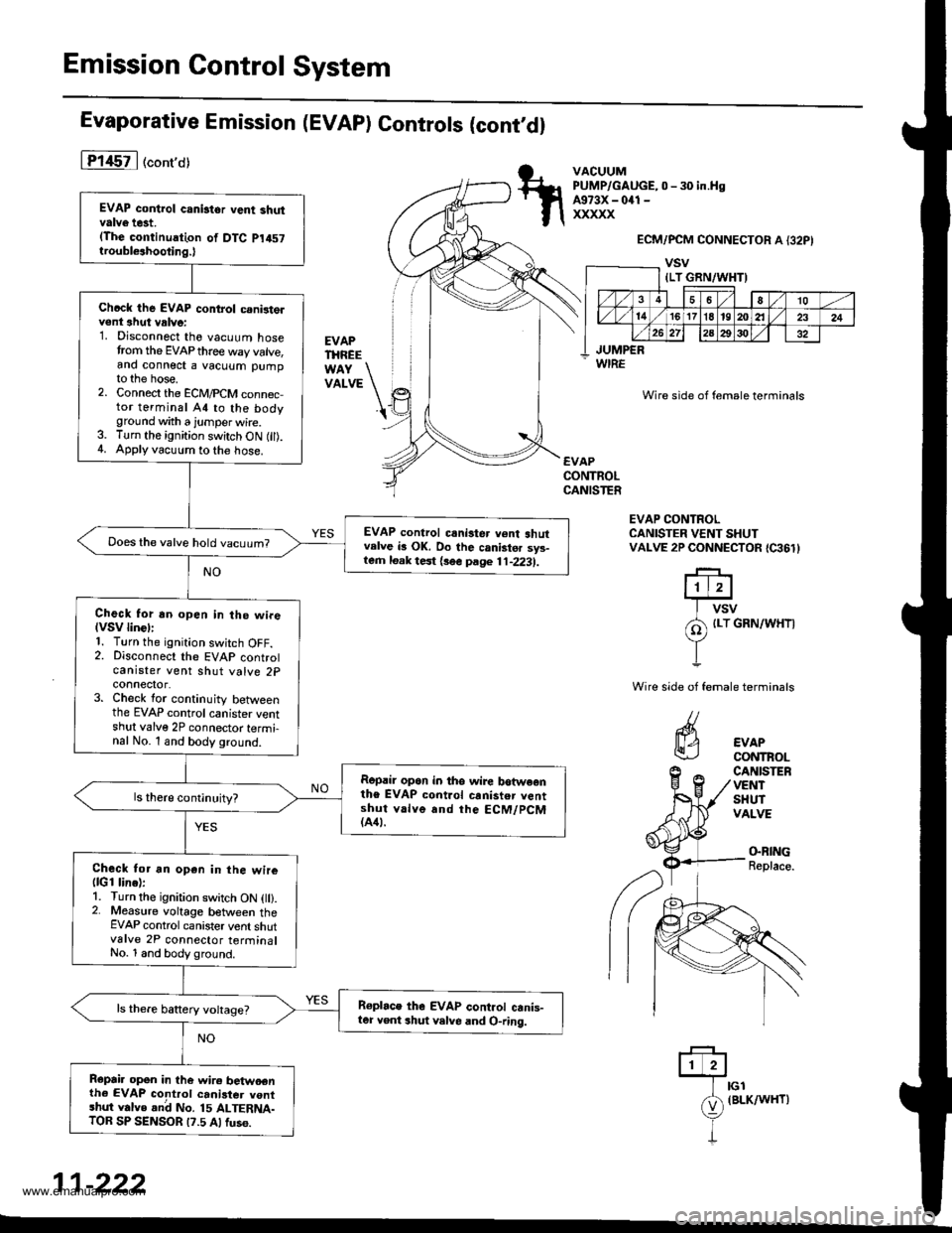
Evaporative Emission (EVAP) Controls (cont,dl
lT145il ("ont'o)
EVAPTHREE
VATVE \'t
VACUUMPUMP/GAUGE,0 - 30 in.HsA973X - 041 -
xxxxx
WIRE
ECM/PCM CONNECTOR A {32PI
vsv
Wire side of female terminals
EVAPCONTROLCANISTER
EVAP CONTROLCANISTER VENT SHUTVALVE 2P CONNECTOR {C361}
riErr+J
I vsv
/A {Lr GRN/WHT|
YI
Wire side of female terminals
CANISTEFVENTSHUTVALVE
EVAPCONTROL
(}BING
Replace.
ffilrcr
e
(BLK/wHr)
I
11-222
EVAP control canistor vent shutvalve t6t.(The continuation of DTC p1457
troubl€ahooting.)
Chcck the EVAP control c.nirt6lvent ahut vrlve:1. Disconnect the vacuum hosetrom the EVAP thre€ way valve,and connect a vacuum pumpto the hose.2. Connect the ECM,PCM conn6c,tor terminal A4 to the bodyground with a jumper wire.3. Turn the ignition switch ON fil).4. Applyvacuum to the hose.
EVAP control crni3ter v6nt shutvelve b OK. Do the canistsr sys-lern loak test {3ee page 11-2231.
Does the valve hold vacuum?
Check for an open in the wireIVSV linGll1. Turn the ignition swjtch OFF.2. Disconnect the EVAP controlcanister vent shut valve 2pconnector.3. Check for continuity betweenthe EVAP control canister ventshul valve 2P connector termi-nal No. l and body ground.
Ropril op6n in tho wire botweonthe EVAP control canister v6ntshut v.lve and the ECM/PCM(A41.
Check tor an open in the wire(lGl line):1. Turn the ignition switch ON l).2. Measure voltage between theEVAP control canister vent shutvalve 2P connector terrninalNo. 1 and body ground.
Roplace thG EVAP cont.ol canis-ter Yent shut velve and O-ring.
Repai. opon in the wire betwoenth6 EVAP control canister vontshut valve .nd No. 15 ALTERNA-TOB SP SENSOR t?.5 Alfus6.
{LT GRN/WHT)
36a10
l4/1617l8't9202l232426 272a2930
JUMPER
www.emanualpro.com
Page 517 of 1395

Automatic Transmission
Special Tools . 14'2OescriptionGeneral Operation . .... 14 3Power Flow . . .. '14_6
Electronic Control System .. .. . . .. .14_15Hydraulic Control .. 14 24Hydraulic Flow....-....... .. . .... .. .. . 14_29Lock'up Syslem .. .'t4'39Electrical SystemComponenl Locdlrons 14 45
PCM Circuil Dragram (A/T Control Svstem)'97 Model ....................... . . .. - . ... .14-46'98Model ................. . ... .. .. .1450'99 00Models.... . .... . . . 1452
PCM Terminal Voltage/Measuring ConditionsA"/T Control System-'97Model ...... ..14'48A,/T Control System -'98 00 Models . . .. . . 14 54
Troubleshooting Procedures .. ..... ... - 14_56Svmotom to comoonent CharlEiectr,cal Syslem -'97 Model . . 14 60Electrical System -'98 - OO Models . .. . . 14_62Electrical Troubleshooting ('97 Model)Troubleshooting Flowaharts .... ..... . .. . . 14_64
Electrical Troubleshooting ('98 - 00 Models)Troubleshootinq Flowclt"n" .... . ....- . .14-93ElectricalTroublesliooting('99 00Models)Troubleshootino FlowchartO/D OFF Indicator Light Does Not Come On 14 131
O/D OFF Indicator Liaht On ConstantlY . . . .1!-132O/D OFF Indicator Light Does Not Come OnEven Though O/D Switch ls Pressed . .... - 14_133
Lock up Control Solenoid Valve A,/B AssemblyTest....................-......... . .14-135Replacement . .ll_135Shifr ControlSolenoid Valve Ay'B Assembl,Test .............................. . .. 14-136
Replacement..............- . .14'136Linear Solenoid AssemblYTest.............................................. .. .... . 14_137Replacement .. . 14138Marnshaftlcountershafl Speed SensorsReplacement ...-... 14_138A/T Gear Position SwitchTest ..........................-... . .. 14-139ReplacementA/T Gear Positionlndicator.................. 14-140
Valve Eodynepair ............................... ..... . . .. - . .. ... 14 192
Assembly .................... .. 1{_193
Valve CapsDesciiption....-........................ .. ...... 14194
tnspeition ................... .. 14' 195
N4ain Valve BodyDisassembly/lnspection/Reassemblv - ...... .. 14_196
Secondarv Valve BodYDisassemblv4nspectron/ReassemblY .. . 14 198
Reoulator Valve Bodvbisassembtv,lnspiction/Reassemblv . 14199
Servo EodvDisassembly/lnspection/Reassembly ... ....14'200
Lock'uo Valve BodYDis;ssembly/lnspection/Reassembly .... . 14_201
MainshaftDisassembly/lnspection/Reassembly .. .. .. ..14'202
Inspection ....-.............. ..11_203
Sealing RingsReilaceient ...... ..... . 14'204
CountershaftDisassembly/lnspection/Reassembly .. . . . . . 11-205
Disassembly/Reassemb|y . . ........ ...... . .. 14_206Inspedron ................ . .... . 14 207
One wav ClutchDisassembly/lnspection/ReassemblY ... 11_209
Sub-shaftDisassembly/lnspection/Reassembly ... . .. . 14-210
oisassembly/Re6ssembly . . ... .-...... . . ..14-211
Sub-shaft BearingsReplacement .......14'212
Clutchllfustrated Index .......... . . .14-213
Disassembly .... .. .....14-216Reassembfy .... . .. .. . 14'218
Differentialllfustrated Index " 14-222Backlash Inspection . .... . .14'223
Bearing Repiacement .. 11-223
Differe-ntial Carrier Replacement .. .. . . . .. ..11-2?4
OifSeal Replacement. . .. 14'225
Side Clearance lnspection . . - .. ... . - ...... . .. 11'226
Transmission Housing BearingsMainshaJVCountershaft EearingsRepfacement .......14221Sub'siralt Eearing Replacement . . . . . . . . . ..11'224
Toroue Converter Housing BearingsMainshattEearing/OilSe6lReplacement . .. l4229
Countershaft Bea;ing Replacement.. .... .. ..14-230
Input Test - '97 - 98 ModelsInput Test '99 - 00 Models
Symptom to-Component ChartHydraulic System ...............
Checking
Removal ...,lllustrated Index (4WD)
Interlock SystemInterlock ControlUnit lnputTest. -..... -.. .... . - 14 144* Key Interlock Solenoid Test .- .. . . . - . . . ..... 14_146* Shift Lock Solenoid Test ..............-.-. . .. . ... .... 14 147*Shift LockSolenoidReplacement...... .. . .. .. 14 148* park pin Switch Test ......... 14 119' Park Pin Switch Replacement- '97 - 98 Models ....... 14-150* Park Pin Swirch/Over Drive (O/Di SwitchReplacemenl '99-00Models . .. 14_151over-Drive (O/D) Switch {'99 00 [4odels]Test........_..................... .......14-152Hydr.ulic System
..............._............... t4 142.................................. 14-143
Control Lever AssemblyR6placement ......,.,Reverse ldler Gear
lllustrated lndex
.......... 14-230
14 231
11-231
1nsta1|ation ..................Park StopInspeclion/AdjustmenlTransfer AssemblY.......14.232
RoadTest.............-.... ........ .StallSpeedTest ....._........................ ....... 14-159Fluid Level......_................... 14'160
Disessembly .................... 14-235Transfer Drive Gear BearingReplacementTrans{er Driven Gesf Shaft BearingReplacementTransfer Housing Roller BearingReplacementTransfer Cov€r A Bearing Outer RaceReplacementTransfer Housing Bearing Outer RaceReplacement ......-..,,,,,.....ReassemblvTransmassaonBeassembly ... -.. .... .14 250
Torque Converier/Drive Plate . .-. .... .. . ... .....14_258
Transmissionlnstatlation .................. ....... 14'259
Cooler Flushing . . ......11-261ATF Cooler HosesConnection.................. ....... 14-266I Shift LeverRemoval/lnstallation . .. 14'261
Disassemblv/Reassemblv - '97 - 98 Models . . 14_264
Disassembli/Reassemblv -'99 - 00 Models . 14-269
Over'Orive (O/D) Switch WireClearanceAdjustment. - ... . . . .. .. . 14'270
Detent Spring Replscement . . -.. ... .14'271*Shift CableAdiustment ....... 14'272
Repfacement.............. . 11'273
14 15711-237
11-237
14-238
$-234
11-23914-240
Transmigrion
Inspeclron ....., ...........Transfer AssemblyRemova1,.,,,..............,lnstallalion ........... .. ...Transmission
14 164
14-16514,167
14-169
End Cover/Transmissio . 14'174Transmission Housing .... ... .. . . .... .. 14-176Torque Converter Housingly'alve Body.. - ... -. 14 178
lllustrated lndex (2WD)End Cover/Transmissio ....... 14 180Transmission Housing . . ... . .. .... ... 14'182Torque Convener Housing/r'alve Body ......- 14-184
End CovefRemovat ...................... ....... 14'186Transmission HousingRemoval ...................... .. 14_188Torque Convener HousingA/alve BodYRemovat ................-..... .-..... 14-190
www.emanualpro.com
Page 519 of 1395

Description
General Operation
The Automatic transmission is a 3-element torque converter and triple-shaft electronically controlled unit which provides 4
speeds forward and 1 reverse speed The unit is positioned in line with the engine'
There are two tvoes of automatic transmission on CR-V; the four-wheel drive (4WD) model ('97 - 00)' and the front-wheel
drive (2WD) model ('98 - 00).
Toroue Converter, G€ars, and Clutches
The torque converter consists of a pump. turbine. and stator assembly in a single unit. The torque converter is connected to
the engine crankshatt. These parts turn together as a unit as the engine turns. Around the outside of the torque converter is
a ring gear which meshes with the starter pinion when the engine is started. The torque converter assembly serves as a fly-
wheel while transmitting power to the transmission mainshaft.
The transmission has three parallel shafts: the mainshaft. the countershaft, and the sub-shaft. The mainshaft is in line with
the engine crankshaft. The mainshaft includes the 1st, 2nd. and 4th clutches, and gears lor 3rd,2nd,4th. reverse and 1st
(3rd gear is integral with the mainshaft, while reverse gear is integral with the 4th gear). The countershaft includes the 3rd
clutch and gears for 3rd,2nd, 4th, reverse, 1st, and park. Reverse and 4th gears can be locked to the countershaft at its cen-
ter, providing 4th gear or reverse, depending on which way the selector is moved. The sub-shaft includes the lst-hold
clutch and gears for lst and 4th.
The gears on the mainshaft are in constant mesh with those on the countershaft and sub-shaft. When certain combinations
of gears are engaged by the ctutches, power is transmitted from the mainshaft to the countershaft to provide E, D!, tr, tr,
and E position ('97 - 98 models). and E. E, E, and E position ('99 - 00 models)'
Electlonic Control
The electronic controt system consists of the Powenrain Control Module (PCM), sensors, a linear solenoid, and four
solenoid valves. Shifting and lock-up are electronically controlled for comfortable driving under all conditions. The PCM is
located below the dashboard, under the kick panel on the passenger's side.
Hydraulic Control
The valve bodies include the main valve body, the secondary valve body, the regulator valve body, the servo body, and
the lock up valve body. They are bolted to the torque converter housing. The main valve body contains the manual valve,
the 1-2 shift valve, the 2nd orifice control valve. the CPB {Clutch Pressure Back-up) valve, the modulator valve, the servo
control valve. the relief valve, and ATF pump gears. The secondary valve body contains the 2-3 shift valve, the 3-4 shift
valve, the 3,4 orifice control valve. the 4th exhaust valve and the CPC (Clutch Pressure Control) valve. The regulator valve
bodv contains the pressure regulator valve, the torque converter check valve, the cooler relief valve, and the lock-up con-
trol valve. The servo body contains the servo valve which is integrated with the reverse shift tork, and the accumulators
The lock-up valve body contains the lock-up shift valve and the lock-up timing valve. The linear solenoid and the shift con-
trol solenoid valve Ay'B are bolted to the outside of the transmission housing, and the lock-up control solenoid valve Ay'B is
bolted to the outside of the torque converter housing. Fluid trom the regulator passes through the manual valve to the
various control valves. The clutches receive fluid from their respective feed pipes or internal hydraulic circuit
ShiftControl Mechanism
input from various sensors located throughout the vehicle determines which shift control solenoid valve the PCM will acti-
vate. Activating a shift control solenoid valve changes modulator pressure, causing a shift valve to move. This pressurizes
a line to one of the clutches. engaging that clutch and its corresponding gear. The shift control solenoid valves A and B are
controlled by the PCM.
Lock-up Mechanism
tn E! position (,97 - 98 modets) and in E position ('99 - O0 models), in 3rd and 4th, and in Del position in 3rd ('97 - 98
models) and in El position with Over,Drive (O/D) is OFF (by pressing rhe O/D switchl in 3rd ('99 - 00 models), pressurized
fluid is drained from the back of the torque converter through a fluid passage, causing the lock-up piston to be held
against the torque converter cover, As this takes place, the mainshaft rotates at the same speed as the engine crankshaft.
Together with hydraulic control, the PcM optimizes the timing of the lock-up mechanism The lock-up valves control the
range of lock-up according to lock-up control solenoid valves A and B, and the linear solenoid. When lock-up control
solenoid valves A and B activate, the modulator pressure changes. The lock-up control solenoid valves A and B and the
linear solenoid are controlled by the PCM.
{cont'd)
14-3
www.emanualpro.com
Page 540 of 1395
Description
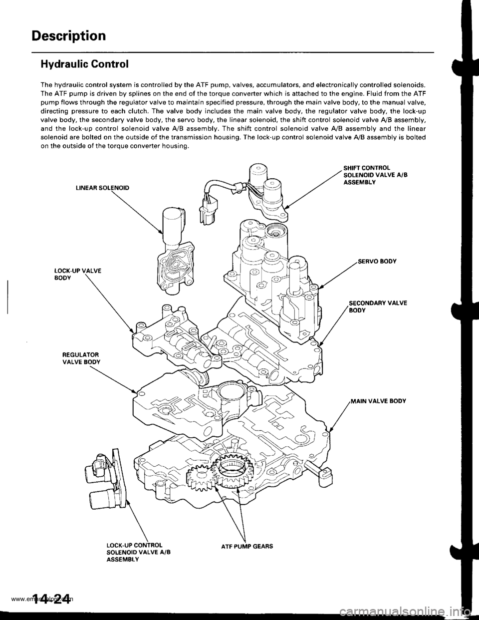
Hydraulic Control
The hydraulic control system is controlled by the ATF pump, valves, accumulators, and electronically controlled solenoids.
The ATF pump is driven by splines on the end of the torque converter which is aftached to the engine. Fluid from the ATF
pump flows through the regulator valve to maintain specified pressure, through the main valve body, to the manual valve,
directing pressure to each clutch. The valve body includes the main valve body, the regulator valve body, the lock-up
valve body, the secondary valve body, the servo body, the linear solenoid, the shift control solenoid valve Ay'B assembly,
and the lock-up control solenoid valve A/B assembly. The shift control solenoid valve A,/B assembly and the linear
solenoid are bolted on the outside of the transmission housing. The lock-up control solenoid valve A,/B assembly is bolted
on the outside of the torque converter housing.
LINEAR
SHIFT CONTROLSOLENOID VALVE A/BASSEMBLY
SECONDARY VALVEBODY
REGULATORVALVE BOOY
VALVE BODY
SOLENOID VALVE A/BASSEMELY
N
ATF PUMP GEARS
14-24
www.emanualpro.com
Page 541 of 1395
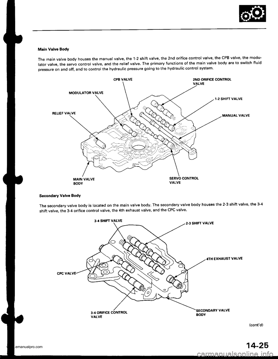
Main Valve Sody
The main valve body houses the manual valve, the 1-2 shift valve. the 2nd orifice control valve. the CPB valve, the modu-
lator valve. the servo control valve. and the relief valve. The primary functions of the main valve body are to switch fluid
pressure on and off, and to control the hydraulic pressure going to the hydraulic control system.
CP8 VALVE2ND ORIFICE CONTROLVALVE
MODULATOR VALVE
RELIEF VALVE
1-2 SHIFT VALVE
MANUAL VALVE
MAIN VALVEBOOY
SERVO CONTROI-VALVE
Secondary valve Body
The secondary valve body is located on the main valve body, The secondary valve body houses the 2-3 shift valve, the 3-4
shift valve, the 3-4 orifice control valve, the 4th exhaust valve, and the CPC valve'
3.' SHIFT VALVE
.TH EXHAUST VALVE
CPC VAL
(cont'd)
14-25
2.3 SHIFT VALVE
3na ORIFICE CONTROLVALVE
VALVE
www.emanualpro.com
Page 542 of 1395
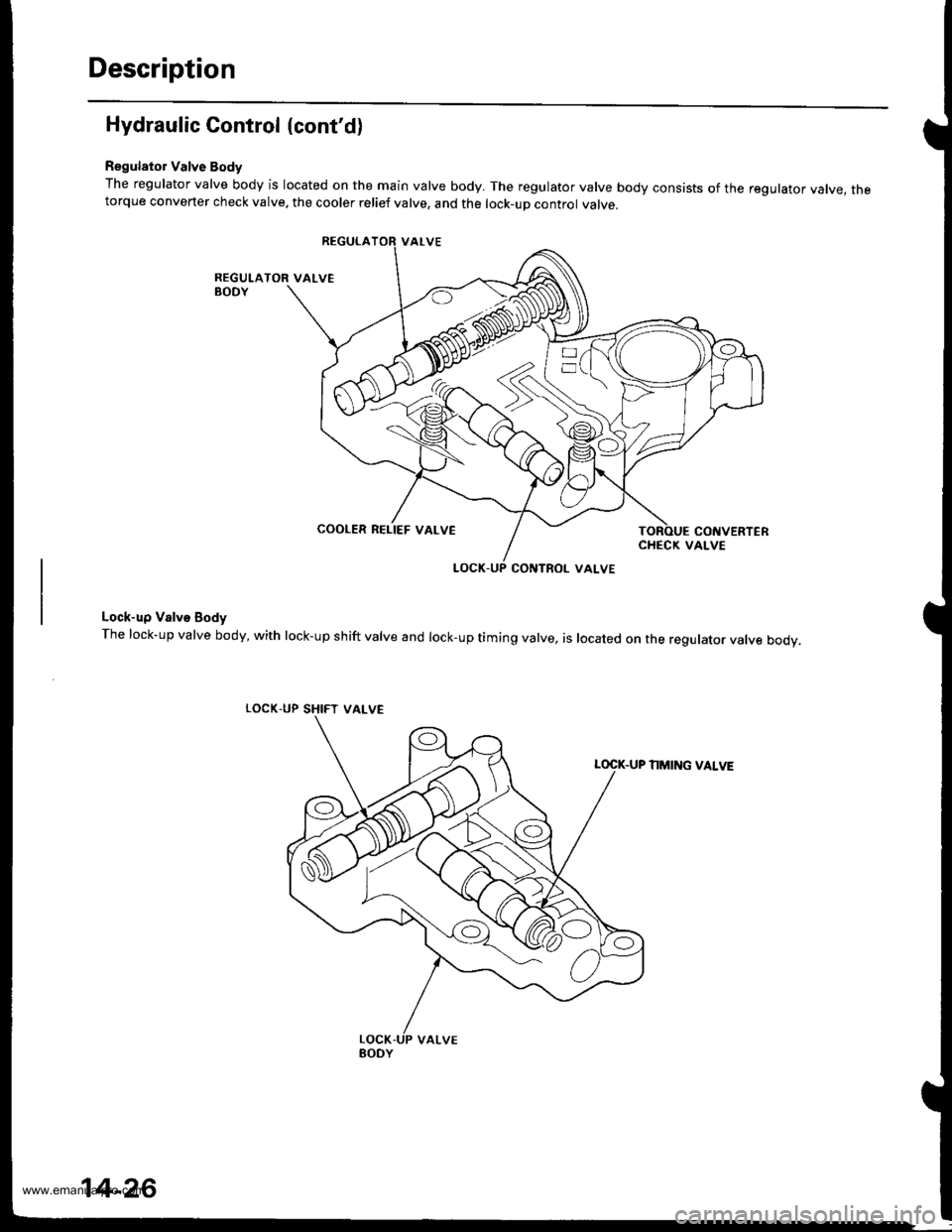
Description
Hydraulic Control (cont'd)
Regulator Valve Body
The regulator valve body is located on the main valve body. The regulator valve body consists of the regulator vatve, thetorque converter check valve. the cooler relief valve, and the lock-up control valve.
Lock-up Valve Body
The lock-up valve body, with lock-up shift valve and lock-up timing valve, is located on the regulator valve body.
LOCK.UP SHIFT
NMING VALVE
COOLER RELIEF VALVE
VALVE
14-26
www.emanualpro.com
Page 544 of 1395
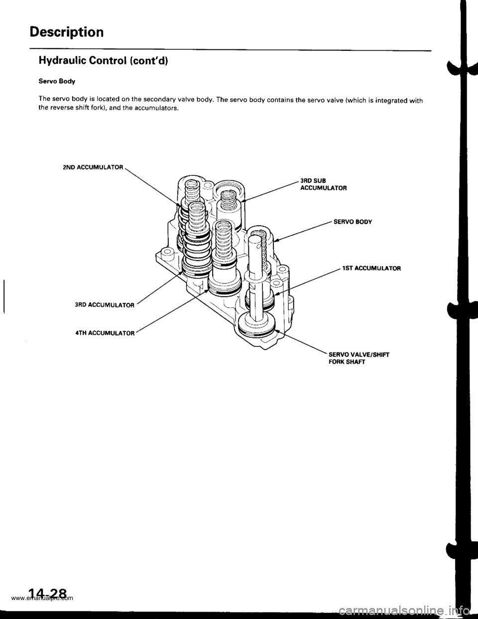
Description
Hydraulic Control (cont'd)
Servo Body
The servo body is located on the secondary valve body. The servo body contains the servo valve (which is integrated withthe reverse shift fork), and the accumulators.
2ND ACCUMULATOR
3RD SUBACCUMULATOR
SERVO BODY
1ST ACCUMULATOR
SERVO VALVE/SHIFTFORK SHAFT
14-28
www.emanualpro.com
Page 581 of 1395
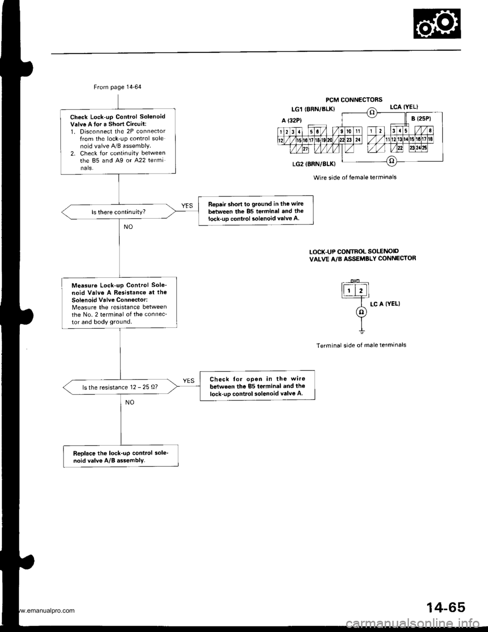
From page 14-64
Check Lock-up Control Sol6noidValve A tor a Short Circuit:1. Disconnect the 2P connectorfrom the lock-up control solenoid valve 4!/B assembly.2. Check for continuity betweenthe 85 and A9 or A22 terminals.
Reprir short to ground in the wire
between the 85 terrninal and thelock-uD contiol solenoid valve A.
Measuro Lock-up Control Sole-
noid Valve A Resistance at the
solenoid valve Connector:Measure the resistance betweenthe No. 2 terminal of the connec-
tor and body ground.
Check for open in the wire
belwe€n the 85 teiminal and the
lock-uo control solenoid valve Als the resistance 12 - 25 O?
Replace the lock-np control sole-noid valve A/B assembly.
PCM CONNECTORS
Wire side of female terminals
LOCK.UP CONTROL SOLENOID
VALVE A/B ASSEMBLY CONNECTOR
----E-
lFr].=--
A Lc A IYELI(nJY
t
Terminal side of male terminals
14-65
www.emanualpro.com