Braking HONDA CR-V 2000 RD1-RD3 / 1.G Workshop Manual
[x] Cancel search | Manufacturer: HONDA, Model Year: 2000, Model line: CR-V, Model: HONDA CR-V 2000 RD1-RD3 / 1.GPages: 1395, PDF Size: 35.62 MB
Page 520 of 1395
Description
General Operation (cont'dl
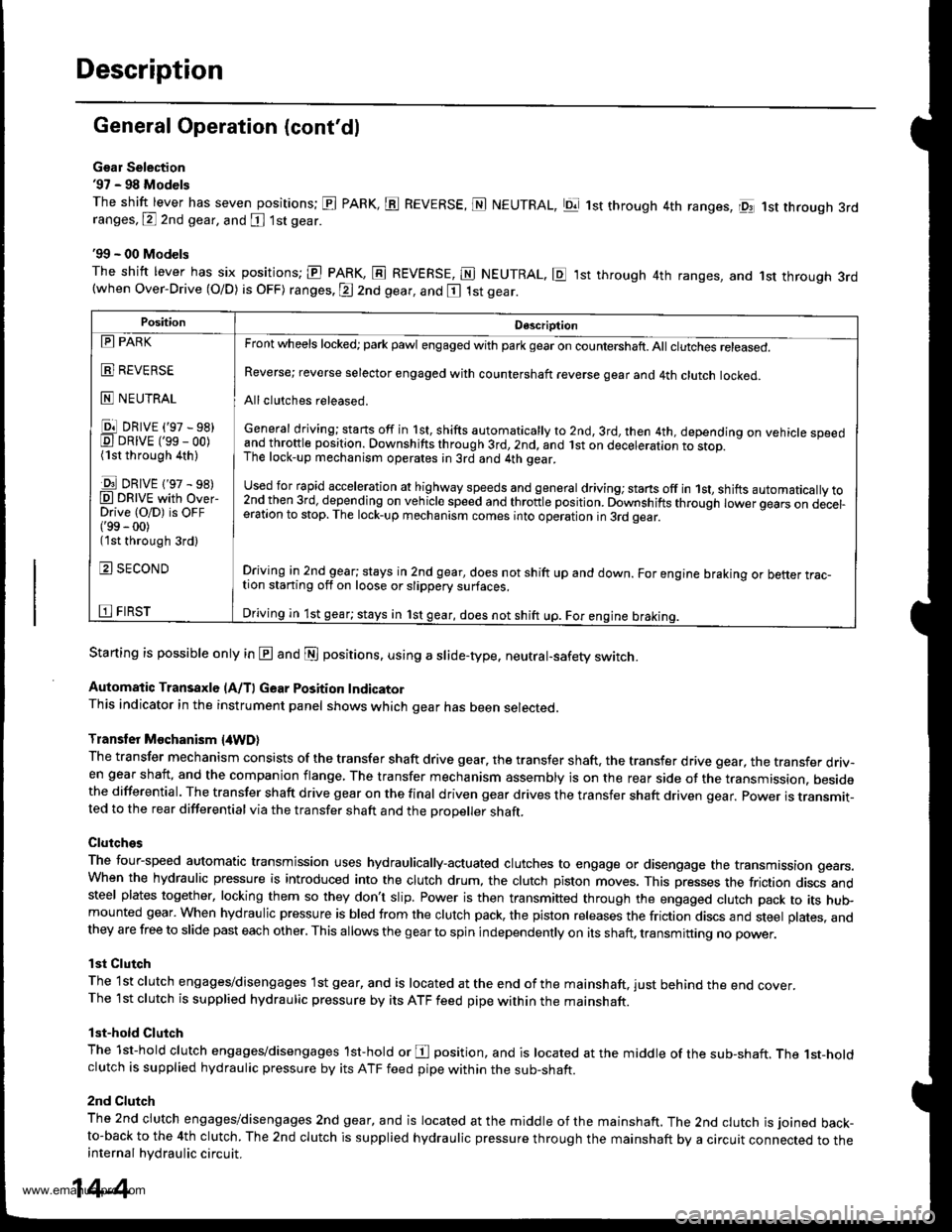
Gsar Selection'97 - 98 Models
The shift lever has seven positions; El PARK, ts REVERSE, N NEUTRAL, Ell 1st through 4th ranges, lpq 1st th.ough 3rdranges, P 2nd gear, and [ 1st gear
'99 - 00 Models
The shitt lever has six positions; El PARK, E REVERSE, E NEUTRAL. E ,lst through 4th ranges, and 1st through 3rd(when Over-Drive (O/D) is OFF) ranges. @ 2nd gear, and E 1st gear.
Starting is possible only in @ and @ positions. using a slide-type. neutral-safety switch.
Automatic Transaxle (A/T) Gear Position IndicatorThis indicator in the instrument panel shows which gear has been selected.
Transler Mochanism {4WD}
The transfer mechanism consists of the transfer shaft drive gear. the transfer shaft. the transfer drive gear, the transfer driv-en gear shaft, and the companion flange, The transfer mechanism assembly is on the rear side ot the transmission. besidethe differential. The transfer shaft drive gear on the final driven gear drives the transfer shaft driven qear. power is transmit-ted to the rear differential via the transfer shaft and the Drooeller shaft.
Clutches
The four-speed automatic transmission uses hydraulically-actuated clutches to engage or disengage the transmission gears.When the hydraulic pressure is introduced into the clutch drum, the clutch piston moves. This presses the friction discs andsteel plates together, locking them so they don't slip. Power is then transmifted through the engaged clutch pack to its hu$mounted gear. When hydraulic pressure is bled from the clutch pack, the piston releases the friction discs and steel plates, andthey are free to slide past each other. This allows the gearto spin independently on its shaft, transmitting no power.
lst Clutch
The 1st clutch engages/disengages lst gear, and is located at the end ofthe mainshaft, just behind the end cover.The 1st clutch is supplied hydraulic pressure by its ATF feed pipe within the mainshaft.
lst-hold Clutch
The 1st-hold clutch engages/disengages 1st-hold or E position, and is located at the middle of the sub-shaft. The 1st-holdclutch is supplied hydraulic pressure by its ATF feed pipe within the sub-shaft.
2nd Clutch
The znd ciutch engages/disengages 2nd gear, and is located at the middle of the mainshaft. The 2nd clutch is joined back-to-back to the 4th clutch. The 2nd clutch is supplied hydraulic pressure through the mainshaft by a circuit connected to theinternal hydraulic circuit.
PositionDescription
Reverse; reverse selector engaged with countershaft reverse gear and 4th clutch locked.
Allclutches released.
General driving; starts off in 1st, shifts automatically to 2nd, 3rd, then 4th, depending on vehicle speedand throftle position. Downshifts through 3rd,2nd, and lst on deceleration to stop.The lock-up mechanism operates;n 3rd and 4th gear.
used for rapid €cceleration at highway speeds and general driving; stans off in 1st, shifts automatically to2nd_then 3rd, dejending on vehicle speed and throttle position. Downshifts through lower gears on decel-eration to stop. The lock-up mechanism comes into operation in 3rd gear.
Driving in 2nd_gear; stays in 2nd gear, does not shift up and down. For engine braking or better trac_tion starting off on loose or slippery surfaces.
Driving in 1st gear; stays in 1st gear, does not shift up. For engine braking.
tll PARK
t!!l l|EvEn>E
E NEUTRAL
Ell DRrvE ('97 - sB)E DRrvE ('ss - oo)(1st through 4th )
E DRrvE {'97 - s8)O DRTVE with over-Drive (O/D) is OFF('99 - 00)(1st through 3rd)
E SECOND
E FIRST
14-4
www.emanualpro.com
Page 525 of 1395
2.
L
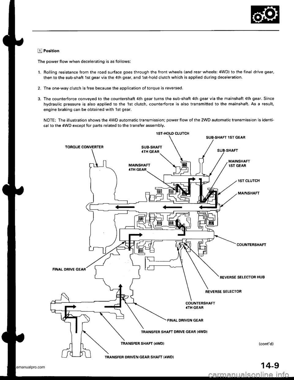
E Position
The power flow when decelerating is as follows:
Rolling resistance trom the road surface goes through the tront wheels (and rear wheels: 4WD) to the final drive gear.
then to the sub-shaft lst gear via the 4th gear. and 1st-hold clutch which is applied during deceleration.
The one-way clutch is free because the application of torque is reversed.
The counterforce conveyed to the countershaft 4th gear turns the sub-shaft 4th gear via the mainshaft 4th gear. Since
hydraulic pressure is also applied to the 1st clutch. counterforce is also transmitted to the mainshaft. As a result,
engine braking can be obtained with'lst gear.
NOTE: The illustration shows the 4WD automatic transmission; power flow of the 2WD automatic transmission is identi-
cal to the 4WD except tor parts related to the transfer assembly.
J.
SUB.SHAFT 1ST GEAR
TOROUE CONVERTER
FINAL DRIVE GEAR
SUB.SHAFT{TH GEAR
MAINSHAFTlST GEAR
lST CLUTCH
MAINSHAFT
COUNTERSHAFT
REVERSE SELECTOR HUB
REVERSE SELECTOR
COUNTERSHAFTIITH GEAR
FINAL ORIVEN GEAR
TRANSFER SHAFT DRIVE GEAR {4WDI
TRANSFEB SHAFT {{WD){cont'd}
lST.HOLD CLUTCH
TRANSFER DRIVEN GEAR SHAFT {,lWDl
14-9
www.emanualpro.com
Page 536 of 1395
Description
Electronic Control System (cont'd)
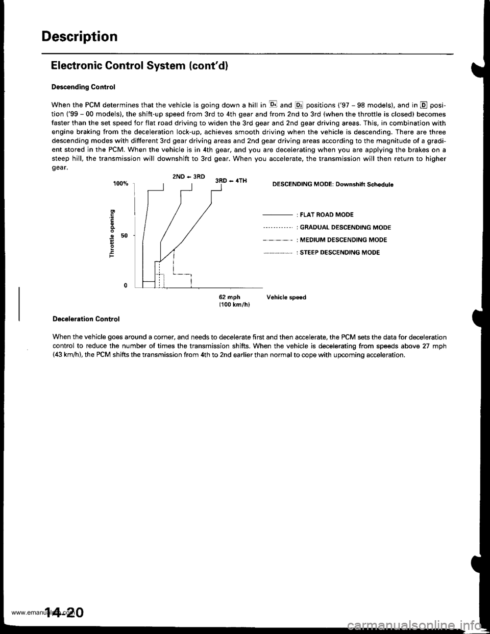
Descending Control
When the PCM determines that the vehicle is going down a hill in E and @ positions ('97 - 98 models). and in @ posi-
tion {'99 - 00 models), the shitt-up speed from 3rd to 4th gear and from 2nd to 3rd (when the throttle is closed) becomes
faster than the set speed for flat road driving to widen the 3rd gear and 2nd gear driving areas. This, in combination with
engine braking from the deceleration lock-up, achieves smooth driving when the vehicle is descending. There are three
descending modes with different 3rd gear driving areas and 2nd gear driving areas according to the magnitude of a gradi-
ent stored in the PCM. When the vehicle is in 4th gear, and you are decelerating when you are applying the brakes on a
steep hill, the transmission will downshift to 3rd gear, When you accelerate, the transmission will then return to higher
gear.
2ND - 3RD 3RD - 4TH
o50
F
DESCENDING MODE: Downshift Schodule
- : FLAT ROAD MODE
----'-----' I GRADUAL DESCENDING MODE
- - - - - : MEDIUM OESC€NOING MODE
. . ... : STEEP DESCENDING MODE
62 mph Vehicle sp€ed1100 km/hl
Deceleration Control
When the vehicle goes around a corner, and needs to decelerate first and then accelerate, the PCM sets the data for deceleration
control to reduce the number of times the transmission shifts. When the vehicle is decelerating from speeds above 27 mph(4i| km,ih), the PCM shifts the transmission from 4th to 2nd earlier than normal to cope with upcoming acceleration,
14-20
www.emanualpro.com
Page 670 of 1395
Symptom-to-Component Chart
Hydraulic System (cont'd)
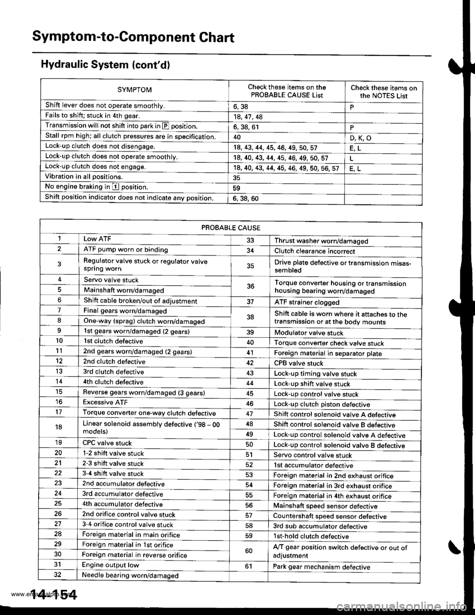
SYMPTOMCheck these items on thePROBABLE CAUSE ListCheck these items onthe NOTES Lisr
Shift lever does not operate smoothly.o, JdPFails to shift; stuck in 4th gear.14, 41 , 48
Transmission will not shift into park in E position.6, 38, 61PStall rpm high; all clutch pressures are in specification.40D,K,OLock-up clutch does not disengage.18, 43, 44, 45, 46, 49,50,57
Lock-up clutch does not operate smoothly.14, 40, 43, 44, 45, 46, 49, 50. 57Lock-up clutch does not engage.'t8, 40, 43, 44, 45, 46, 49, 50, 56, 57Vibration in all positions.
No engine braking in I position.59
Shift position indicator does not indicate anv position,6. 38, 60
PROBABLE CAUSE
I 33 Thrust washer worn/damaged
ATF pump worn or binding34Clutch clearance incorrect
Regulator valve stuck or regulator valvespflng wornDrive plate delective or transmission mtsas-sembled
Servo valve stuck5ttTorque converter housing or transmissionhousing bearing worn/damagedMainshaft worn/damaged
Shift cable broken/out of adjustmentATF strainer clogged
7Final gears worn/damaged38Shift cable is worn where it attaches to thetransmission or at the body mountsIOne-way (sprag) clutch worn/damaged
1st gears worn/damaged {2 gears)39Modulator valve stuck10lst clutch defective40Torque converter check valve stuck112nd gears worn/damaged (2 gears)41Foreign material in separator plate't22nd clutch defectiveCPB valve stuck
t53rd clutch defective43Lock-up timing valve stuck144th clutch defective44Lock-up shift valve stucktcReverse gears worn/damaged (3 gears)Lock-up control valve stuck16Excessive ATF46Lock-up clutch Diston defective17Torque converter one-way clutch defective47Shift control solenoid valve A defecttve
18Linear solenoid assemblv defective (,98 - OOmodels)48Shift control solenoid valve B dsfectrve
49Lock-up control solenoid valve A defective'19CPC valve stuckLock-up control solenoid valve B deleqtve20l-2 shift valve stuck51Servo control valve stuck212-3 shift valve stuck52lst accumulator defective3-4 shift valve stuck53Foreign material in 2nd exhaust orifice2nd accumulator defective54Foreign material in 3rd exhaust orifice3rd accumulator defectiveForeign material in 4th exhaust orifice4th accumulator defective56Mainshaft speed sensor defective262nd orifice control valve stuckCountershaft speed sensor defective273-4 orifice control valve stuck583rd sub accumulator defective2aForeign material in main orifice59lst-hold clutch defective29Foreign material in lst orifice60A/T gear position switch defective or out ofadjustment30Foreign material in reverse orifice
31Engine output low61Park gear mechanism defective32Needle bearing worn/damaged
14-154
www.emanualpro.com
Page 674 of 1395
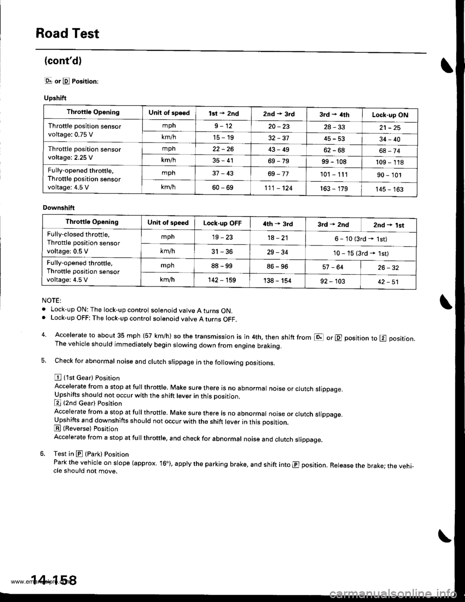
Road Test
(cont'd)
lgrr or E Position:
Upshift
NOTE:
. Lock-upON:The lock-up control solenoid valve A turns ON.. Lock-up OFF: The lock-up control solenoid valve A turns OFF.
4. Accelerate to about 35 mph (57 km/h) so the transmission is in 4th. then shift from E or E position to E position.The vehicle should immediately begin slowing down from engine braking.
5. Check for abnormal noise and clutch slippage in the following positions.
E {1st Gear) Position
Accelerate from a stop at full throttle, Make sure there is no abnormal noise or clutch slippage.Upshifts should not occur with the shift lever in this position.
E (2nd cear) Position
Accelerate from a stop at fuI throttre. Make sure there is no abnormar noise or crutch srippage.Upshifts and downshifts should not occur with the shift lever in this position.
E (Reverse) Position
Accelerate from a stop at full throttle. and check for abnormal noise and clutch slippage.
6. Test in E (Park) Position
Park the vehicle on slope (approx. 16"), apply the parking brake, and shift into E position. Release the brake; the vehi-cle should not move.
Throftle OpsningUnit of sps€dlsi + 2nd2nd * 3rd3rd + ilthLock-up ON
Throttle position sensor
voltage: 0.75 V
mph9-1220-2328-33
km/h15-1945-5334-40
Throttle position sensor
voltage; 2.25 V
mph22-2643-49oz - ott68-74
km/h35-4169-7999 - 108109 - 118
Fully-opened throttle,
Throttle position sensor
voltage: 4.5 V
mph37-43101 - 11190 - 101
k-/h60-69111 - 124163 - 179145 - 163
Downshift
Throttle OpeningUnit ot speedLock-up OFFi{th + 3rd3rd * 2ndznd + lst
Fully-closed throttle,
Throttle position sensor
voltage; 0.5 V
mpn19-231A - 2'l6 - 10 {3rd - 1st)
km/h5t-5D29-3410 - 15 (3rd * 1st)
Fully-opened throttle,
Throttle position sensor
voltage: 4,5 V
mph88-9986-9657 -6426-32
km/h142 - 't59138 - 15492 - 10342-51
14-158
www.emanualpro.com
Page 794 of 1395

Description
Rear Differential
Outline
The Real-time 4WD-Dual Pump System model has a hydraulic clutch and a differential mechanism in the rear differential
assembly. Under normal conditions, the vehicle is driven by the front wheels. However, depending on to the driving force
of the front wheels and the road conditions. the system instantly transmits appropriate driving force to the rear wheels
without requiring the driver to switch between 2WD (tront wheel drive) and 4WD (four wheel drive). The switching mecha-
nism between 2WD and 4WD is integrated into the rear differential assembly to make the system light and compact.
ln addition, the dual-pump system switches off the rear-wheel-drive force when braking in a forward gear. This allows the
braking system to work properly on models equipped with an Anti-lock Braking System (ABS).
Construction
The rear differential assembly consists of the torque control differential case assembly and the rear differential carrier
assembly. The torque control differential case assembly consists of the differential clutch assembly, the companion
flange, and the oil pump body assembly. The rear differential carrier assembly consists of the differential mechanism. The
differential drive and driven gears are hypoid gears.
The oil pump body assembly consists of the front oil pump, the rear oil pump, the hydraulic control mechanism, and the
clutch piston. The clutch piston has a disc spring that constantly provides the differential clutch assembly with a preset
torque to Drevent abnormal sound.
The clutch guide in the differential clutch assembly is connected to the propeller shaft via the companion flange, and it
receives the driving force lrom the transfer assembly. The clutch guide rotates the clutch plate and the front oil pump in
the oil pump body.
The clutch hub in the differential clutch assembly has a clutch disc that is splined with the hypoid drive pinion gear. The
hypoid drive gear drives the rear oil pump.
The front and rear oil pumps are trochoidal pumps. The rear oil pump capacity is 2.5 percent larger that the front oil pump
to handle the rotation difference between the front and rear wheels caused by worn front tires and tight corner braking.
The oil pumps are designed so the fluid intake works as a fluid discharge when the oil pumps rotate in reverse. Genuine
Honda CVT fluid is used instead of differential fluid.
Operation
When there is a difference in rotation speed between the front wheels (clutch guide) and rear wheels (hypoid driven gear),
hydraulic pressure from the front and rear oil pumps engages the differential clutch, and drive force from the transler
assembly is applied to the rear wheels.
The hydraulic pressure control mechanism in the oil pump body selects 4WD mode when the vehicle is started abruptly,
or when accelerating in a forward or reverse gear (causing rotation difference between the front and rear wheels). or
when braking in reverse gear {when decelerating). lt switches to 2WD mode when the vehicle is driven at a constant speed
in forwar! or reverse gear (when there is no rotation difference between the front and rear wheels), or when braking in a
fo rwa rd gear (when decelerating).
To protect the system, the differential clutch assembly is lubricated by hydraulic pressure generated by the oil pumps in
both 4WD and 2WD modes. Also, the thermal switch relieves the hydraulic pressure on the clutch piston and cancels 4WD
mode if the temDerature of the differential fluid rises above normal.
www.emanualpro.com
Page 797 of 1395
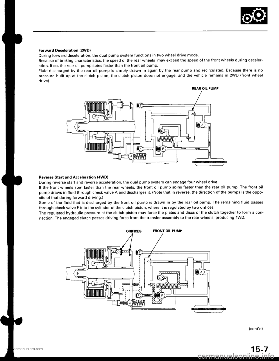
Forward Deceleration l2WDl
During forward deceleration, the dual pump system functions in two wheel drive mode.
Because of braking characteristics, the speed of the rear wheels may exceed the speed ol the front wheels during deceler-
ation. lf so, the rear oil pump spins faster than the front oil pump.
Fluid discharged by the rear oil pump is simply drawn in again by the rear pump and recirculated. Because there is no
pressure built up at the clutch piston. the clutch piston does not engage, and the vehicle remains in 2WD (front wheel
drive).
Reverse Start and Acceleration (4WD)
During reverse start and reverse acceleration, the dual pump system can engage four wheel drive.
lf the front wheels spin faster than the rear wheels, the front oil pump spins faster than the rear oil pump. The front oil
pump draws in fluid through check valve A and discharges it. {Note that in reverse, the direction of the pumps is the oppo-
site of that during forward driving.)
Some of the fluid that is discharged by the front oil pump is drawn in by the rear oil pump. The remaining fluid passes
through check valve F into the cylinder of the clutch piston, where it is regulated by two orifices.
The regulated hydraulic pressure at the clutch piston may force the plates and discs of the clutch together to form a con-
nectlon. The engaged clutch passes driving force from the transfer assembly to the rear wheels, producing 4WD.
oRtFtcEsFRONT OIL PUMP
{cont'd)
15-7
REAR OIL PUMP
www.emanualpro.com
Page 798 of 1395
Description
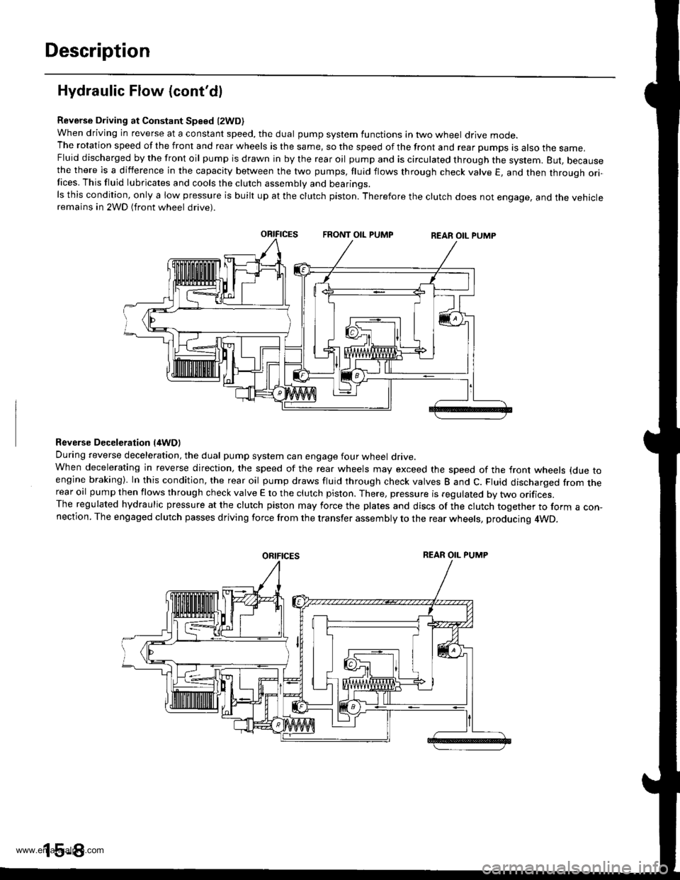
Hydraulic Flow (cont'dl
Reverse Driving at Constant Speed l2WD)when driving in reverse at a constant speed, the dual pump system functions in two wheel drive mode.The rotation speed of the front and rear wheels is the same, so the speed of the front and rear pumps is also the same,Fluid discharged by the front oil pump is drawn in by the rear oil pump and is circulated through the system. But, becausethe there is a difference in the capacity between the two pumps, fluid flows through check valve E, and then through ori-Iices. This fluid lubricates and cools the clutch assembly and bearings.ls this condition, only a low pressure is built up at the clutch piston. Therefore the clutch does not engage, and the vehicleremains in 2WD (front wheel drive).
Reverse Deceleration l/tWDl
During reverse deceleration, the dual pump system can engage four wheel drive.When decelerating in reverse direction, the speed of the rear wheels may exceed the speed of the front wheels (due toengine braking). In this condition, the rear oil pump draws fluid through check valves B and C. Fluid discharged from therear oil pump then flows through check valve E to the clutch piston. There, pressure is regulated by two orifices.The regulated hydraulic pressure at the clutch piston may force the plates and discs of the clutch together to form a con,nection. The engaged clutch passes driving force from the transfer assembly to the rear wheels, producing 4WD.
oRtFtcEsREAR OIL PUMP
www.emanualpro.com
Page 934 of 1395
Front Brake Pads
Inspection and Replacement (cont'dl
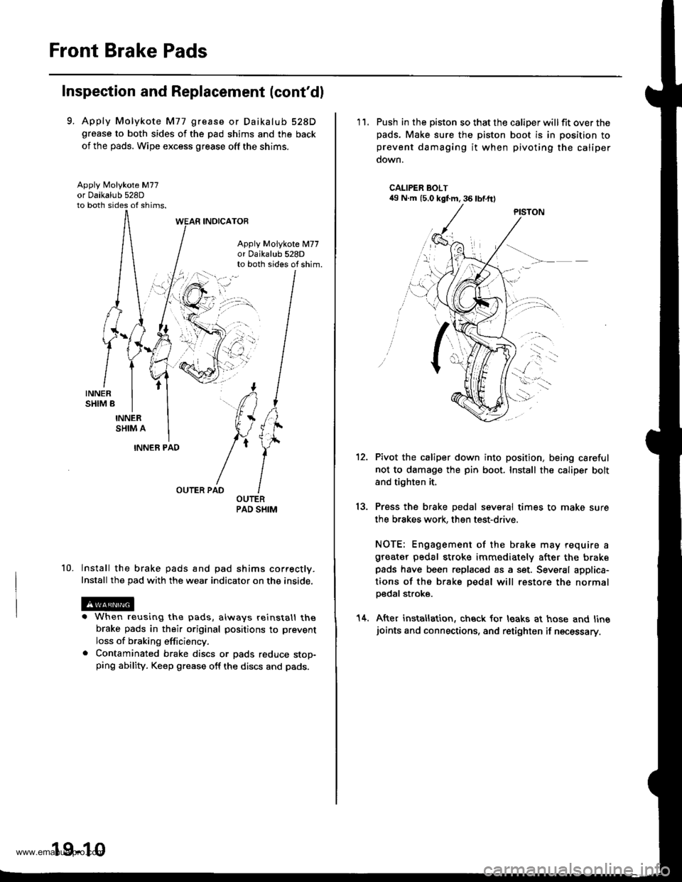
9. Apply Molykote M77 grease or Daikalub 528Dgrease to both sides of the pad shims and the back
of the pads. Wipe excess grease off the shims.
Apply Molykote M77
to both sides of shims.
INOICATOR
Apply Molykote M77or 0aikalub 528Dto both sides of shim.
10.
INNER PAD
OUTER PAD
lnstall the brake pads and pad shims correctly.
Install the pad with the wear indicator on the inside.
. When reusing the pads, always reinstall thebrake pads in their original positions to prevent
loss of braking efficiency.. Contaminated brake discs or pads reduce stop-ping ability. Keep grease off the discs and pads.
19-10
'11. Push in the piston so that the caliper willfit over thepads. Make sure the piston boot is in position toprevent damaging it when pivoting the caliper
down.
CALIPER BOLT49 N.m (5.0 kgf.m, 36 lbf.ftl
13.
Pivot the caliper down into position, being careful
not to damage the pin boot. Install the caliper bolt
and tighten it,
Press the brake pedal several times to make sure
the brakes work, then test-drive.
NOTE: Engagement of the brake may require agreater pedal stroke immediately after the brakepads have been replaced as a set. Several applica-
tions of the brake pedal will restore the normalpedal stroke.
After installation, check for leaks at hose and linejoints and connections, and retighten if necessary.
14.
www.emanualpro.com
Page 936 of 1395
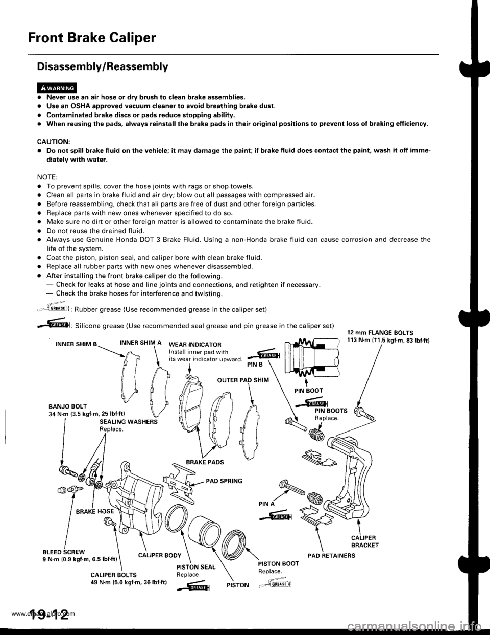
Front Brake Caliper
Disassembly/Reassembly
. Never use an air hose or dry brush to clean brake assemblies.
. Use an OSHA approved vacuum cleaner to avoid breathing brake dust.
. Contaminated brake discs or pads reduce stopping ability.
. When reusing the pads, always reinstallthe brake pads in their original positions to prevent loss ol braking efficiency.
CAUTION:
. Do not spill brake fluid on the vehicle; it may damage the paint; if brake fluid does contact the paint, wash it off imme-
diatelY with water.
NOTEI
. To prevent spills, cover the hose joints with rags or shop towels.
. Clean all pans in brake fluid and air dry; blow out all passages with compressed air.
. Before reassembling, check that all parts are free of dust and other foreign particles.
. Replace parts with new ones whenever specified to do so.
. Make sure no dirt or other foreign matter is allowed to contaminate the brake fluid.
. Do not reuse the drained fluid.
. Always use Genuine Honda DOT 3 Brake Fluid. Using a non-Honda brake fluid can cause corrosion and decrease the
life of the system.
. Coat the piston, piston seal, and caliper bore with clean brake fluid.
. ReDlace all rubber oarts with new ones whenever disassembled.
. After installing the front brake caliper do the following.- Check for leaks at hose and line joints and connections, and retighten if necessary.- Check the brake hoses for interference and twistinq.
SHIM
12 mm FLANGE BOLTS113 N.m (11.5 kgtm,83lbf.ftlINNER
ft
il1
#
\i
#
PIN B
OUTER PAO SHIM
PAD SPRING
IPIN BOOT
-Cr
SEALING WASHERSReplace.4dd*
ERAKE PADS
'f,-rre
/ tto*l "o"\
t@I
/\'
sLreo 6cnew \I N m 10.9 kStm, 6.5 lbnft)
\
6-
>PIN A
-6, {
CALIPER BOOY
CALIPER EOLTS49 N.m {5.0 kgl.m, 36lbf.ftl
PISTON AOOTReplace.
"..-a=a-...,--"sEqriPISTON
t".:jil,,.'.1!!!!9!il: Rubber grease (Use recommended grease in the caliper set)
irf"i:;;T::fl,-J'I",0 .@
--6, Silicone grease (use recommended seal grease and p,n grease in the caliper set)
INNER SHIM BWEAB INDICATOR
EANJO BOLT34 N.m {3.5 kgf m,25 lblftl
PISTON SEALReplace.
AFACKET
19-12
PAD RETAINERS
www.emanualpro.com