Icm HONDA CR-V 2000 RD1-RD3 / 1.G Workshop Manual
[x] Cancel search | Manufacturer: HONDA, Model Year: 2000, Model line: CR-V, Model: HONDA CR-V 2000 RD1-RD3 / 1.GPages: 1395, PDF Size: 35.62 MB
Page 31 of 1395
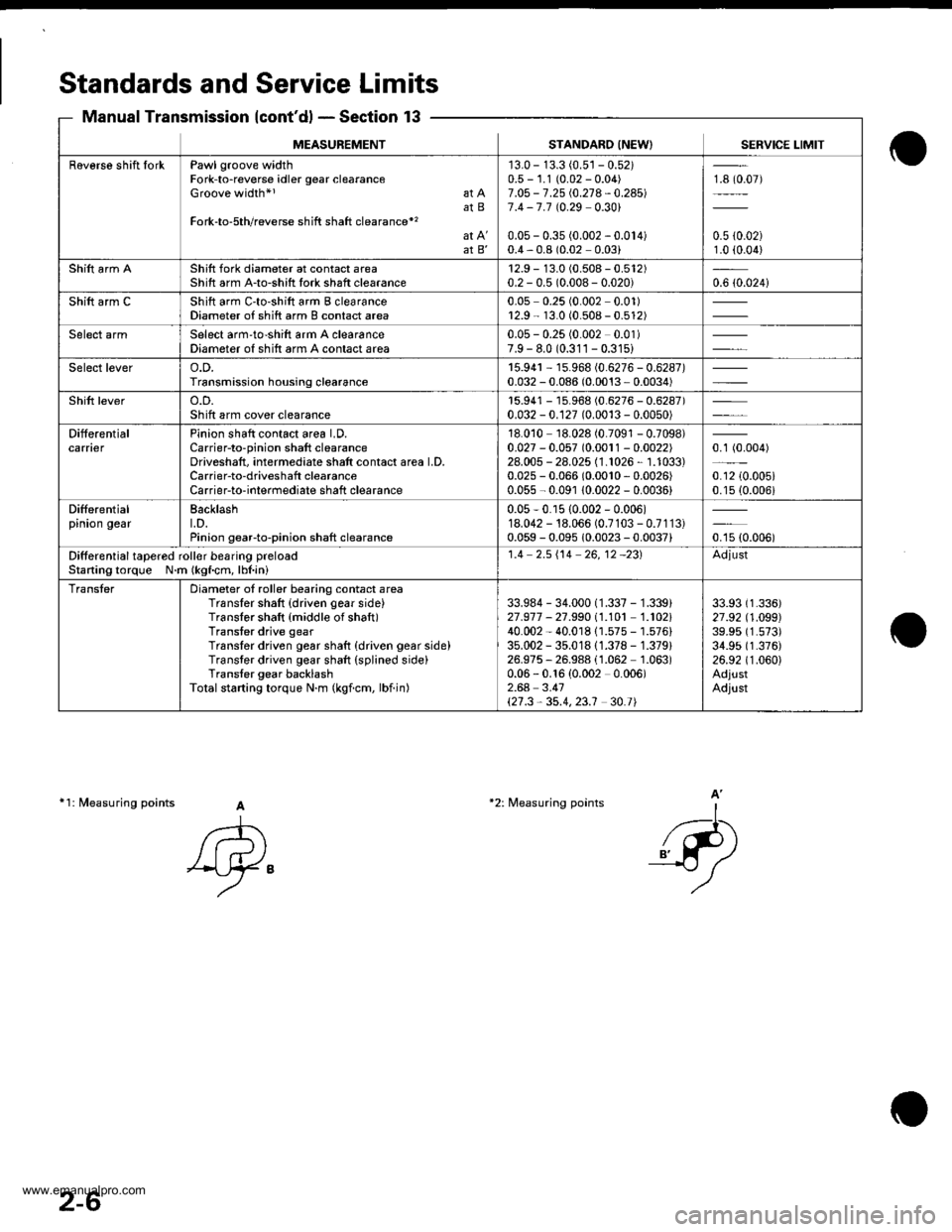
Standards and Service Limits
Manual Transmission {cont'd} - Section 13
11: fuleasuring points A
A
'Ay"
-l-...
_{-P)
A'*2: Measuring points
MEASUREMENTSTANDARO INEW) SERVICE LIMIT
Raverse shift IorkPawl groove widthFork-to-reverse idler gear clearanceGroove width*l at AatBFork-to-5th/reverse shift shaft clearance*'�
at B'
'13.0 - 13.3 (0.5'�j - 0.52)0.5 - 1.1 (0.02 - 0.04)7.O5 - 7.25 i.0.21 4 - 0.24517.4 -7.7 t0.29 0.301
0.05 - 0.35 (0.002 - 0.014)0.4,0.8 (0.02 0.03)
18 (0.07)
0.5 {0.02)1.0 (0.04)
Shift arm AShift fork diameter at contact areaShift arm A-to-shitt tork shaft clearance12.9 - 13.0 (0.508 - 0.512)0.2 - 0.5 (0.008- 0.020)0.6 {0.024i
Shift arm CShift arm C'to-shift arm B clearanceDiameter of shift arm B contact area0.05 0.25 (0.002 0.01)r2.9 - 13.0 (0.508 - 0.512)
Select armSelect arm'to-shift arm A clearanceDiameter of shift arm A contact area0.05 - 0.25 (0.002 0.01)7.9 - 8.0 (0.311 - 0.31s)
Select levero.D.Transmission housing clearance15.94r - 15.968 (0.6276 - 0.6287)0.032 - 0.086 (0.0013 - 0.0034)
Shift levero.D.Sh ift arm cover clearancer5.941 - 15.968 (0.6276 - 0.6287)0.032 - 0.127 (0.0013 - 0.0050)
DifferentialcarnerPinion shaft contact area LD.Carrier-to-pinion shaft clearanceDriveshaft, intermediate shatt contact area LD,Carrier-to-driveshaft clearanceCarrierto-interrnediate shaft clearance
18.010 18.028 (0.7091 - 0.7098)0.027 - 0.057 (0.0011 - 0.0022)28.005 - 28.025 (1.1026, 1.1033)0.025 - 0.066 (0.0010,0.0026)
0.055 - 0.091 10.0022 - 0.0036)
0.1 (0.004)
0.12 {0.005i0.15 (0.006i
Differentialpinion gearBacklasht.D.Pinion gearto-pinion shaft clearance
0.05-0.r5 {0.002 - 0.006)18.042 - 18.066 (0.7103 - 0.7113)0.059 - 0.095 10.0023 - 0.0037)oru ro.ooor
Ditferential tapered roll€r besring preloacStaning torque N.m (kgf.cm, lbl.ini
1.4 2.5i'14 26,12 -231Adjust
TransterDiameter of roller bearing contact areaTransler shaft {driven gear side}Translor shaft {middle of shaft)Transter drive gearTranslor driven gear shaft {driven gear side)Transter driven gear shaft (splined side)Trans{er gear backlashTotalstarting torque N.m (kgicm, lbiin)
33.984 - 34.000 (1.337 - 1.339)21.977 - 27.99011.101 1.102140.002 - 40.01811.575 - 1.576)35.002 - 35.01811.378 - 1.379)26.975, 26.988 (1.062 1.063)0.06 - 0.16 {0.002 0.006)2.64 3.41\21.3,35.4,23.1 30.t|
33.93 (1.336)
27 .92 (1 .O99)39.95 (1.573)
34.95 (1.376)
26.92 (1.060)
AdjustAdjust
2-6
www.emanualpro.com
Page 68 of 1395
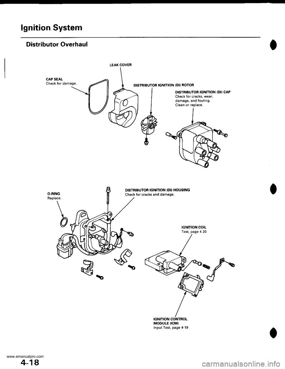
lgnition System
Distributor Overhaul
CAP SEALCheck for damage.DISTRIBUTOR IGNITION IDII ROTOR
OISTRIBUTOR IGNITION {DII CAPCheck for cracks, wear,damage, and to!ling.Clean or replace.
O.RINGReplace.
b
OISTBIBUTOR IGI{ITION IDO HOUSING
Check for cracks and damage.
IGNITION COILTest, page 4 20
@_
IGNITION CONTROLMODULE {ICMIInput Test, page 4-19
LEAK COVEN
4-18.
www.emanualpro.com
Page 69 of 1395
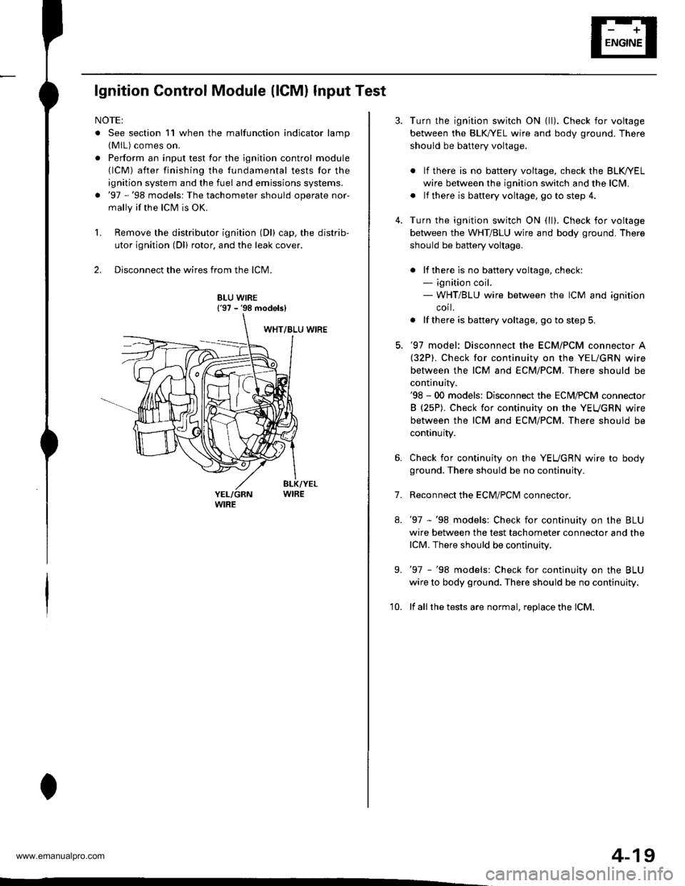
lgnition Control Module (lCMl Input Test
NOTE:
. See section 11 when the malfunction indicator lamp(MlL) comes on.
. Perform an input test for the ignition control module(lCM) after finishing the fundamental tests for the
ignition system and the fuel and emissions systems.
. '97 -'98 models: The tachometer should operate nor-
mally if the ICM is OK.
L Remove the distributor ignition (Dl) cap, the distrib-
utor ignition (Dl) rotor, and the leak cover.
2. Disconnect the wires from the lCM.
8LU WIRE{'97 - '98 models}
4-19
7.
Turn the ignition switch ON {ll). Check for voltage
between the BLK,^/EL wire and body ground. There
should be battery voltage.
. lf there is no battery voltage, check the BLK/rEL
wire betlveen the ignition switch and the lclvl.
. lf there is baftery voltage, go to step 4.
Turn the ignition switch ON (ll). Check for voltage
between the WHT/BLU wire and body ground. There
should be battery voltage.
. lf there is no batteryvoltage, check:- ignition coil.- WHT/BLU wire between the ICM and ignition
corl.
. lf there is battery voltage, go to step 5,
'97 model: Disconnect the ECM/PCM connector A(32P). Check for continuity on the YEL/GRN wire
between the ICM and ECM/PCM. There should be
continuity.'98 - 00 models: Disconnect the ECM,PCM connector
B (25P). Check for continuity on the YEUGRN wire
between the ICM and ECM/PCM. There should be
continuity.
Check for continuity on the YEUGRN wire to body
ground. There should be no continuity.
Reconnect the ECM/PClvl connector.
'97 -'98 models: Check for continuity on the BLU
wire between the test tachometer connector and the
lCM. There should be continuity.
'97 -'98 models: Check for continuity on the BLU
wire to body ground. There should be no continuity.
lf all the tests are normal, replace the lCM.
9.
'10.
www.emanualpro.com
Page 247 of 1395
1 2\3 156
16
18iJq11 12 13 ra15'11l8
cr25 tPCM-Cl
ct23 {PCM-Alc124 (PCM,B)
cr26 tPicM-ol
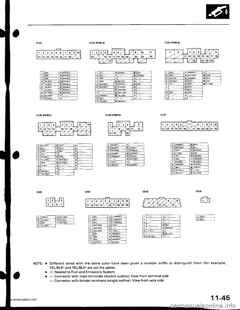
Different wires with the same color have been given a number suffix to distinguish them (for exampie,
YEUBLKT and YEUBLK2 are not the same).
O: Related to Fuel and Emissions Svstem.- Connector with male terminals (double outline): View from terminal side
- Connector with female terminals (single outline): View from wire side
NOTE: o
oo
,,
.t
o
an
123a5X67A910
rr l1213lat5t611t819 20
!to
lit
Doo
nn
ii)
o
a
12568910
11 112t3!il'16It't8t9 20
11-45
www.emanualpro.com
Page 269 of 1395

Powertrain Control Module Terminal Arrangement -'97 Model
FCM CONNECTOR A (32P)NOTE: Standard battery voltage is 12 V.
Wire side of lemale terminals
f€rminalnumlreJWirecolor
Telminalnama
DescriptionSignal
YELlNJ4 (No.4 FUELINJECTOR)Drives No. 4 {uel injector.With engine running: duty controlled
2BLUlNJ3 (No.3 FUELINJECTOR)Drives No. 3luel injector.
REDlNJ2 {No.2 FUELINJECTOR)Drives No.2 tuel injector.
BRNlNJl (No. l FUELINJECTOR)Drives No. 1 fuel injector.
5BLK WHTSO2SHIC (SECONDARY
HEATED OXYGEN SENSOR HEATER CONTROL)
D ves secondary heated oxygensensor heater.With ignition switch ON {ll): battery voltageWith fully warmed up engino running: dutycontrolled
6BLKAr'YHT
PO2SHTC (PRIMARY
HEATED OXYGENSENSOR HEATERCONTROL}
Drives primary heated oxygensensor heater,With ignition switch ON lll): battery voltagewith fully warmed up engine running: dutycontroll6d
I8RN/BLKLGl (LOGIC GROUND}Ground forthe PCM control circuit.Less than 1.0 V at all times
10BLKPG1 lPOWER GROUND}Ground for the PCM power circuit.
l1YEUELKIGPl lPOWER SOURCE}Power source for the PCM controlcircuit.
With ignition switch ON (ll): battery voltageWith ignition switch OFF: 0 V
12BLI(BLUIACV {IDLE AIRCONTROL VALVE}Drives IACV.With €ngine running: duty controlled
REDryEL
PCS (EVAP PURGECONTFOL SOLENOIDVALVE)
Drives EVAP purge controlsolenoid valve.
With engine running, engine coolantbelow 154'F (68"C): battery voltageWith engine running, engine coolantabove 154"F (68"C): duty controlled
16GRN/VELFLR (FUEL PUMP RELAY)Drives Iuel pump relay.0 V for two seconds after turning ignition
switch ON lll), then battery voltage
118LI(REDACC (A,/C CLUTCHRELAY}Drives Ay'C clutch relay.With comoressor ON: 0 VWith compressor OFF: baftery voltage
18GRN/ORNMIL (MALFUNCTION
INDICATOR LAMP}Drives MlL.With MIL turned ON: 0 VWith MIL turned OFF: baftery voltage
19*WHT/GRNALTC (ALTERNATOR
CONTROL}Sends alternator control signal.With tully warmed-up engine running:
battery voltageDuring driving with smallelectrical load:0 '
20YEUGRNICM (IGNITION CONTROLMODULE)Sends ignition pulse.With ignition switch ON (ll): baftery voltageWith engine running: pulses
22BRN/BLKLG2 (LOGIC GROUND}Ground tor the PCM control circuit.Less than 1.0 V at alltimes
23BLKPG2 {POWER GROUND}Ground lor the PCM power circuit.
24YEUBLKIGP2 {POWER SOURCE}Power source for the PCM controlcircuit.
With ignition switch ON (ll): battery voltage
With engine switch OFF: 0 V
27GRNFANC (RADIATOR FANCONTROL)Drives radiator {an relay.With radiator fan running: 0 VWith radiator fan stopped: baftery voltage
*: USA
{cont'd)
11-67
www.emanualpro.com
Page 337 of 1395
![HONDA CR-V 2000 RD1-RD3 / 1.G Workshop Manual
Vehicle Speed Sensor (VSSI
lPosoo-]-. |posol l-
97 modol:
The scan tool indicates Diagnostic Trouble Code {DTC} P0500*�or P0501*r: A range/perfor-
mance in the Vehicle Speed Sensor (VSS) circuit. HONDA CR-V 2000 RD1-RD3 / 1.G Workshop Manual
Vehicle Speed Sensor (VSSI
lPosoo-]-. |posol l-
97 modol:
The scan tool indicates Diagnostic Trouble Code {DTC} P0500*�or P0501*r: A range/perfor-
mance in the Vehicle Speed Sensor (VSS) circuit.](/img/13/5778/w960_5778-336.png)
Vehicle Speed Sensor (VSSI
lPosoo-]-'. |posol l-'
'97 modol:
The scan tool indicates Diagnostic Trouble Code {DTC} P0500*'�or P0501*r: A range/perfor-
mance in the Vehicle Speed Sensor (VSS) circuit. * I ; A/T*2i Mfi
FCM CONNECTORS
A t32Pl
LG1(BRN/BLK)
NOTE: Do not use the engine to turn thofront wheels with th6 rear wheels on theground. The 4WD system will engage andthe vehicle will suddenlv Iurch forward.
Wire side ot female terminals
LGl
{BRN/BLKI
(cont'd)
11-135
The MIL hes boen roported on.DTC m501 is 3tor€d.
Problom verificetion:1. Test'drive the vohicle.2. Check the vehicle speed withthe scan tool,
lntormittent tailure, rystom b OKat thia timo. Chock tor poor con-nection3 or 10o3o wires rt C129lvss) .nd rr rhe Pcfr4,
ls the correct speed indicated?
Chock for an open in tho PiCM:1. Turn the ignition switch OFF.2. Block the rear wheels and setthe parking brake.3. Jack up the lront of the vehicleand support it with saletystands.4. Turn the ignition switch ON (ll).
5. Elock the right front wheel andslowly rotate the left trontwheel by hand.6. Measure voltage betweenPCM connector terminals C18and A9.
Substitulc a known-good PCMand .och6ck. It symptom/indicd.tion go.a away, .cplaco tho origi-nel FCM.
Doesthe voltage pulse 0 Vand 5 V or battery voltage?
Check for a .hort in the PCM:L Turn the ignition switch OFF.2. Disconnect the PCM con'nector C (31P).
3. Turn the ignition switch ON (ll).
4. Elock the right front wheeland slowly rotate the left front
5. Measure vohage between PCMconnector terminals C18 andA9.
Substituto e known-good PCMand rochock. f rymptom/indica-tion goos rwry, roplsc. tho origi-nalFCM.
Doesthe voltage pulse 0 Vand 5 V or battery voltage?
- Repair short in the wirebetween the PCM lC18l,cruise control unit, speodo-meter, and VSS,- Repair opon in the wirebetween the PCM {C181 .ndrhe vss.- f wire is OK. tost lho VSS l3oosoction 231.
www.emanualpro.com
Page 481 of 1395
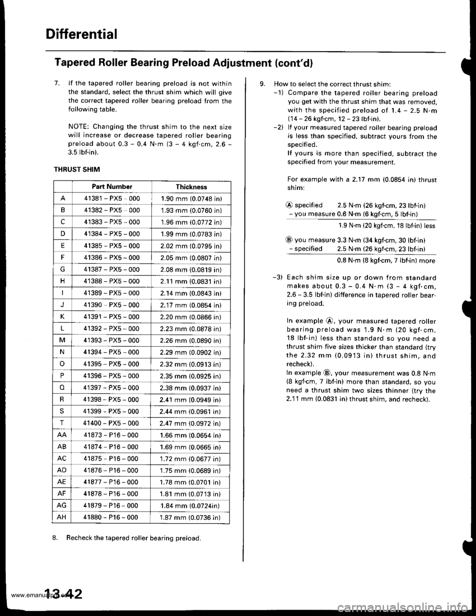
Differential
Tapered Roller Bearing Preload Adjustment (cont'd)
7. lf the tapered roller bearing preload is not within
the standard, select the thrust shim which will give
the correct tapered roller bearing preload from the
following table.
NOTE: Changing the thrust shim to the nexl size
will increase or decrease tapered roller bearingpreload about 0.3 - 0.4 N.m (3 - 4 kgf.cm, 2.6 -
3.5 lbf.in).
THRUST SHIM
8. Recheck the tapered roller bearing preload.
Part Numbe.Thickness
41381 - PX5 0001.90 mm (0.0748 in)
B41382 - PX5 0001.93 mm {0.0760 in)
c41383-PX5-000'1.96 mm (0.0772 in)
n41384-PX5-0001.99 mm (0.0783 in)
E41385-PX5-0002.02 mm (0.0795 in)
F41386-PXs-0002.05 mm (0.0807 in)
G41387-PXs-0002.08 mm (0.0819 in)
n41388-PX5-0002.11 mm (0.0831 in)
41389-PX5-0002.14 mm (0.0843 in)
J41390-PXs-0002.'17 mm (0,0854 in)
K41391 - PX5 - 0002.20 mm (0.0866 in)
4'1392-PX5-0002.23 mm (0.0878 in)
M41393-PX5-0002.26 mm (0.0890 in)
N41394-PX5-0002.29 mm (0.0902 in)
o41395, PXs - 0002.32 mm (0.09'13 in)
P41396-PX5-0002.35 mm (0.0925 in)
o41397-PX5-0002.38 mm (0.0937 in)
4'�t398-PXs-0002.41 mm (0.0949 in)
S41399-PXs-0002.44 mm (0.0961 in)
T41400-PXs-0002.47 mm (0.0972 in)
41873-P16-0001.66 mm (0.0654 in)
AB41874-Pl6-0001.69 mm (0,0665 in)
AC41875 P16 - 000'1.72 mm (0.0677 in)
AD41876-P16-0001.75 mm (0.0689 in)
AE41877-P16-0001.78 mm (0.0701 in)
AF41878-P16-0001.81 mm (0.07'13 in)
41879-P16-000'1.84 mm (0.0724in)
AH41880-P16-0001.87 mm {0.0736 in)
13-42
9. How to select the correct thrust shim:-1) Compare the tapered roller bearing preload
you get with the thrust shim that was removed,
with the specified preload of 1.4 - 2.5 N.m(14 -- 26 kgfcm, 12-23lbtinl.-2) lf your measured tapered roller bearing preload
is less than specified. subtract yours from the
specified,
lf yours is more than specified, subtract the
specified from your measurement.
For example with a 2.17 mm (0.0854 in) thrust
shiml
@ specified 2.5 N.m (26 kgf.cm,23 lbiin)- you measure 0.6 N.m (6 kgf.cm,5 lbf.in)
1.9 N.m (20 kgicm, 18 tbt.in) tess
@ you measure 3.3 N.m (34 kgf.cm,30 lbf.in)- specified 2.5 N.m (26 kgncm,23 lbf.in)
0.8 N.m (8 kgf.cm,7lbt.in) more
Each shim size up or down from standard
makes about 0.3 - 0.4 N.. (3 - 4 kgf'cm,
2.6 - 3.5 lbf.in) difference in tapered roller bear-
ing preload.
In example @, your measured tapered roller
bearing preload was 1.9 N.m (20 kgf.cm,
18 lbf.in) less than standard so you need a
thrust shim five sizes thicker than standard {trythe 2.32 mm (0.0913 in) thrusr shim. and
recheck).
ln example @, your measurement was 0,8 N.m
{8 kgf.cm, 7 lbf.in) more than standard, so you
need a thrust shim two sizes thinner (try the
2.1'l mm {0.0831 in) thrust shim, and recheck).
www.emanualpro.com
Page 584 of 1395
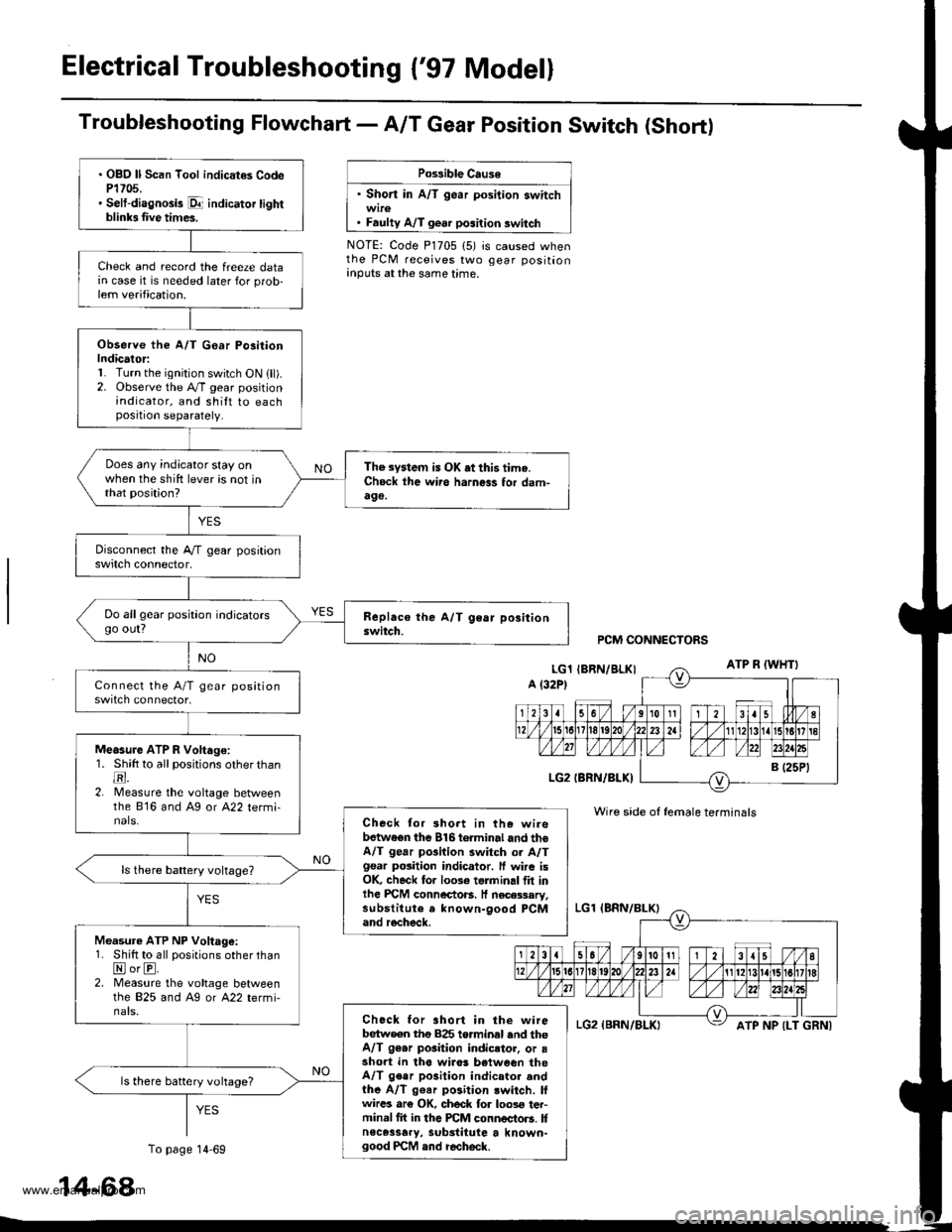
Electrical Troubleshooting {'97 Model}
Troubfeshooting Flowchart- AIT Gear Position Switch (Short)
Po$ible Cause
' Short in A/T gear position switch
. Faulty A/T gear position switch
NOTE: Code P1705 (5) is caused whenthe PCM receives two gear positionanputs at the same time.
. OBO ll Scan Tool indicat€s CodeP1705.' Selt-diagnosis p1- indicator tightblinb Iive times.
Check and record the freeze datain case it is needed later for prob-lem verification.
Observe the A/T G€ar Po3itionIndicator:1. Turn the ignition switch ON lll).2. Observe the A./T gear positionindicator, and shilt to eachposition separately.
Does any indicator stay onwhen the shift lever is not inthat position?
The system is OK .t this time.Ch6ck ihe wii6 harness for dam-490,
Do allgear position indicatorsgo out?
Measure ATP R Voltago:1. Shitt to all positions other thantr.2. lMeasure the voltage betweenthe 816 and Ag or A22 termi-nals.Check tor 3hort in the wirebetwaen the 816torminal and thoA/T gear pGilion switch or A/Tgsar posiiion indicator. ff wire isOK, check for 10036 torminal flt inlhe PICM connectoB. It necessary,substitute a known-9ood PCMand recheck.
Measure ATP NP Voltage:1. Shift to all positions other thanNorE.2. Measure the vohage betweenlhe 825 and Ag or A22 termi-nals.Chock for ahort in the wirebetw€en tho 825 torminal end theA/T 96.r pGition indicstor, or asho.t in tha wiro! b€tween theA/T gear po3ition indicator andthe A/T g€ar position lwitch. lfwircs ar€ OK, ch6ck for loos€ ter-minal fit in the PCM connectors. Itnece3sary, substitute a known-good PCM and recheck.
ls there battery vohage?
PCM CONNECTORS
Wire side of female terminals
ATP NP {LT GRNI
14-68
To page 14-69
www.emanualpro.com
Page 616 of 1395
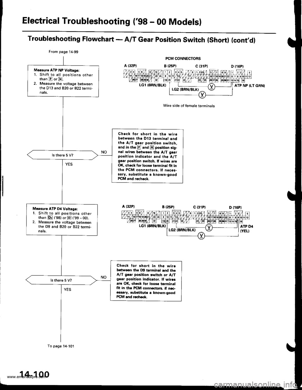
Electrical Troubleshooting ('98 - 00 Modelsl
Troubleshooting Flowchart - A/T Gear position switch (short) (cont'dl
FCM CONNECTORS
B t25Plc (31P)
Wire side of lemale terminals
A t32Pl
LGl {BRN/BLK)
From page 1 4-99
To page 14-101
Measur. ATP NP Voltago:1. Shift to all positions otherthan E or E.2. Measure the voltage belweenthe 013 and 820 or 822 termi-nats.
Check for short in the wir6b.twoen tha Dl3 terminal andthe A/T go.r polition 3witch,and in th6 El and E poiition sig-nal wir.! betwoen the A/T garrpo3ition indicetor and the A/Tgarr position switch. lf wi.6s areOK, check for loole torminal fit intho PCM connccto.s, lf necca-sary, lubstituto a known-goodPCM and rocheck.
Mcrsure ATP D4 Vohrg6:1. Shift to all positions otherthan E {'98) or El ('99 - oo).2. Measure the voltage betweenthe Dg and 820 or 822 termi-nals.
Check tor Bhort in the wi..bctw6cn thg Dg torminal and theA/T ge.r position .witch or A/Tgeor poaition indicator. lf wiaaaare OK, ch.ck lor loose torminalfit in the PICM conn.cto6. lf n€c-e3sary, subgthute r lnown-goodrcM and roch6d(.
ATP NP ILT GRNI
a t32Pl
LGl IERN/BLK}
14-100
www.emanualpro.com
Page 1219 of 1395
t -, IrJr--------11-.----..1'\-J
IITBLK/YEL I BLUMHT
BLKMHTJ 'i- | g
ltY
(}-.
YEL _
TURN SIGNAUHAZARD WARNINGswrTcH
YYY
IGNITIONCONTROLI/lODULEIcM)
f7
IBLU
1.,
No.s i10A) .--......_FUSE LEFT RIGHT
MALFUNCTIONINDICATORtA[rP ([,{tL){1.4W1
l.,CRN/ORN
I
PCM
COOLANTTEII,4PERATURESENDINGUNIT
BLK
T
G552
(cont'd)
23-59
G401G402
www.emanualpro.com