Rear glass switch HONDA CR-V 2000 RD1-RD3 / 1.G Workshop Manual
[x] Cancel search | Manufacturer: HONDA, Model Year: 2000, Model line: CR-V, Model: HONDA CR-V 2000 RD1-RD3 / 1.GPages: 1395, PDF Size: 35.62 MB
Page 982 of 1395
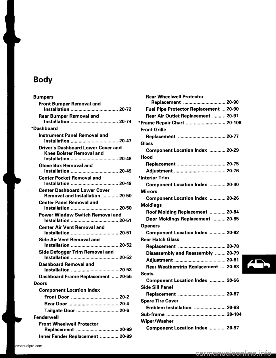
Body
Bumpers
Front Bumper Removal and
fnstaflation .........20-72
Rear Bumper Removal and
fnstaflation .........20-74
'Dashboard
lnstrument Panel Removal and
lnstallation .........20-47
Driver's Dashboard Lower Cover and
Knee Bolster Removal and
Installation .........20-48
Glove Box Removal and
lnstallation .........20-49
Center Pocket Removal and
lnstallation .........20-49
Center Dashboard Lower Cover
Removal and lnstallation ............ 20-50
Center Panel Removal and
lnstallation .........20-50
Power Window Switch Removal and
lnstallation .........20-51
Center Air Vent Removal and
lnstallation .........20-51
Side Air Vent Removal and
fnstallation .........20-52
Side Defogger Trim Removal and
fnstallation .........20-52
Dashboard Removal and
lnstallation .........20-53
Dashboard Frame Replacement ..... 20-55
Doors
Component Location Index
Front Door ,,...,,,,20-2
Rear Door ...........20-4
Tailgate Door ................................ 20-6
Fenderwell
Front Wheelwell Protector
Replacement .....20-89
Inner Fender Replacement .,.....,.,.... 20-89
Rear Wheelwell Protectol
Replacement .....20-90
Fuel Pipe Protector Replacement ... 20-90
Rear Air Outlet Replacement .......... 20-91
*Frame Repair Chart .............................. 20-106
Front Grille
Repf acement .........20-77
Glass
Component Location Index ............ 20-29
Hood
Replacement ......,,,20-75
Adjustment ............20-76
*lnterior Trim
Component Location Index ............ 20-40
Mirrors
Component Location Index .........,,, 20-26
Moldings
Roof Molding Replacement ............ 20-84
Door Moldings Replacement .......... 20-85
Openers
Component Location Index ............ 20-92
Rear Hatch Glass
Replacement .........20-74
Disassembly and Reassembly ........ 20-79
Adiustment ............20-81
Rear Weatherstrip Replacement .... 20-83
Seats
Component Location Index ............ 20-56
Side Sill Panel
Repfacement .........20-87
Spare Tire Cover
Emblem Installation ........................ 20-88
Sub-frame ..................20-104
Wiper/Washer
Component Location lndex ,,,,,....... 20-97
www.emanualpro.com
Page 1029 of 1395
Dashboard
SRS components are located in this area. Review the SRS
component locations, precautions, and procedures in the
SRS section (24) before performing repairs or service.
GAUTION:
. When prying with a tlat-tip screwdriver, wrap h withproteqtive tape, and apply protective tape around the
relat€d parts, to prevent damage,
. Put on glovgs to protect your hands.
NOTE: Take care not to scratch the dashboard and relatedpans.
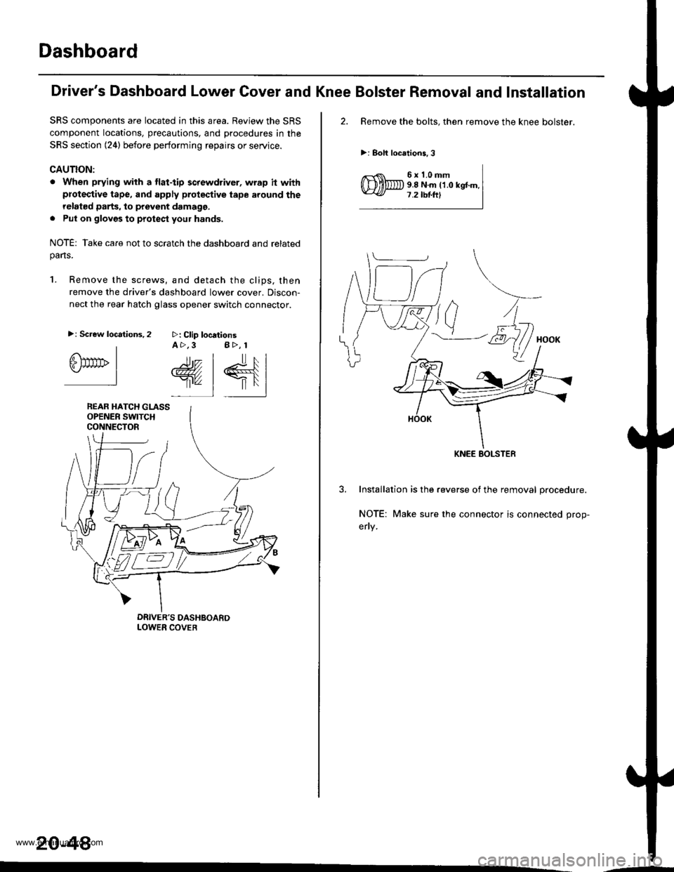
1. Remove the screws, and detach the clips, then
remove the driver's dashboard lower cover. Discon-
nect the rear hatch glass opener switch connector.
>: Clip locationsA >,3 B>, 1
rr.- | lr, l
@, | €{lr'" 1 |'l
>: Screw locations,2
IGlTtrrrb I.-l
REAR HATCH GLASSOPENER SWITCHCONNECTOR
20-48
'-
Driver's Dashboard Lower Cover and Knee Bolster Removal and Installation
2. Remove the bolts. then remove the knee bolster.
>: Boh locations,3
6x1.0mm9.8 N.m ('1.0 kgtm.7.2 tbtftl
3. Installation is the reverse of the removal procedure.
NOTE: Make sure the connector is connected prop-
erly.
KNEE BOLSTEF
www.emanualpro.com
Page 1188 of 1395
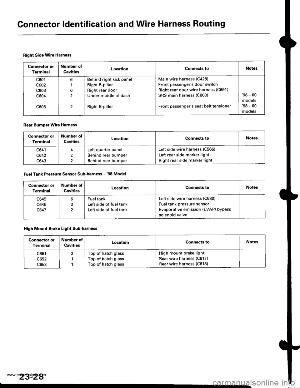
Gonnector ldentification and Wire Harness Routing
Right Side Wire Harness
Connec{or or
Tsrminal
Number of
CavitiesLocationConnests toNotes
c601
c602
c603
c604
6'1
2
2
Behind right kick panel
Right B-piller
Right rear door
Under middle of dash
Right B-piller
Main wire harness (C428)
Front passenger's door switch
Right rear door wire harness (C691)
SRS main harness {C808)
Front passenger's seat belt tensioner
'98 - 00
mooets'98 - 00
models
Rear Bumper Wire Harness
Connector ol
Terminal
Number ot
CavitiesLocationConnocts toNotes
c641
c642
c643
4
2
2
Left quarter panel
Behind rear bumper
Behind rear bumper
Left side wire harness (C566)
Left rear side marker light
Right rear side marker light
Fuel Tank Pressure Sensor Sub-harness - '98 Model
Connector or
Terminal
Number ot
CavitiesLocationConnects toNot63
c645
c646
c647
?
2
Fueltank
Left side of fuel tank
Left side of fuel tank
Left side wire harness (C580)
Fuel tank pressure sensor
Evaporative emission (EVAP) bypass
solenoid valve
High Mount Brake Light Sub-harnoss
Conneslor or
Terminal
Number of
CavitiesLocationConnec-ts toNotes
c651
c652
c653
2
1
1
Top of hatch glass
Top of hatch glass
Top of hatch glass
High mount brake light
Rear wire harness (C617)
Rear wire harness (C618)
23-28
www.emanualpro.com
Page 1190 of 1395
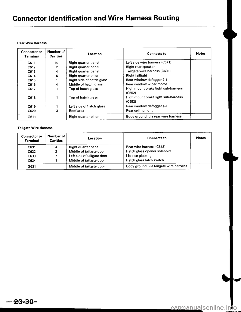
Gonnector ldentification and Wire Harness Routing
Rear Wiro Harness
Connector or
Terminal
Number of
CavitiesLocationConnects toNotes
c61l
c612
c613
c614
c617
c618
c619
c620
14
2
6
1
1
'I
1
Right quarter panel
Right quarter panel
Right quarter panel
Right quaner piller
Right side of hatch glass
Middle of hatch glass
Top of hatch glass
Top of hatch glass
Left side of hatch glass
Roof area
Left side wire harness (C57'l)
Right rear speaker
Tailgate wire harness (C631)
Right taillight
Rear window defogger (+)
Rear window wiper motor
High mount brake light sub-harness
(c652)
Hjgh mount brake light sub-harness
{c653)
Rear window defogger (-)
Rear ceiling light
G611Right quarter pillerBody ground, via rear wire harness
Tailgate wire Harness
Connestor or
Terminal
Number of
CavitiesLocationConnects toNoles
c633
c634
2
2
1
Right quarter panel
Middle of tailgate door
Left side of tailgate door
Middle of tailgate door
Rear wire harness (C613)
Hatch glass opener solenoid
License plate light
Hatch glass latch switch
I/iddle of tailgate doorBody ground, via tailgate wire harness
23-30
www.emanualpro.com
Page 1203 of 1395

Power Distribution
Fuse-to-Gomponent(sl Index (numerical sequence)
Under-hood Fuse/Rolay Box:
41
43
44
46
47
48
49
50
52
Capacity
'100 A
40A
7.5 A
15 A
40A
7.5 A
30A
204
204
15 A
10A
40A
40A
204
20A
Capacity
40A
204
7.5 A
wiro ColorFuseCircuit(s) Prot€cted
A
lgnition switch (BAT)
lntegrated control unit
Ceiling lights
Spotlights
PGM-Fl main relay
Not used
No. 7, 8, 10, 11 fuse in the under-dash fuse/relay box
Audio unit
Clock {'98 - 00 models)
Data link connector ('98 - 00 models)
ECM (VBU) {'98 - 00 models: M/T)
Heater control panel
PCM (VBU) (A./T)
Combination light switch (via under-dash fuse/relay box)
No. 20, 33 fuse in the under-dash fuss/relay box
Not used
Rear window defogger (via relay)
Door lock control unit
Hatch glass opener solenoid
Keyless door lock control unit ('98 - 00 models)
Horn relay
Horns (via relay)
via brake switch:
ABS control unit
Brake lights
Cruise control unit
ECM ('98 - 00 models: M/T)
High mount brake iight
PCM (4./T)
Trailer lighting connector
Turn signal/hazard relay (via switch)
Option connector (+B)
No. 6 fuse in the under-dash fuse/relay box
Blower motor (via relay)
Condenser fan motor (via relay)
Ay'C compressor clutch (via relay)
Radiator fan motor (via relay)
Wire Color Circuitls) Protoct
53
54
50
WHT/BLK
WHT/RED
WHT/BLK
WHT/BLU
WHT/BLU
WHT
WHT/GRN
WHT/GRN
WHT/GRN
WHT/BLK
WHT/RED
BLU/WHT
WHT
RED
BLK/RED
Under-hood ABS Fuss/nehy Box:
Fusg
61WHT
WHT/GRN
BRN/YEL
ABS pump motor {via relay}
ABS control unit
ABS control unit
{cont'd)
23-43
www.emanualpro.com
Page 1208 of 1395
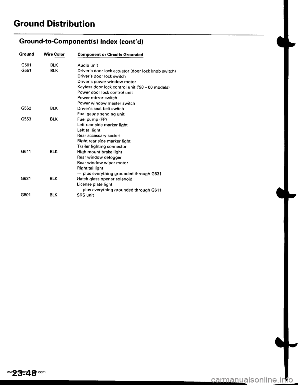
Ground Distribution
Ground-to-Component(sl Index (cont'dl
Wire ColorGround
G552
G501
G801
BLK
BLK
BLK
BLK
Component or Circuits Grounded
Audio unit
Driver's door lock actuator (door lock knob switch)
Driver's door lock switch
Driver's power window motor
Keyless door lock control unit ('98 - 00 models)
Power door lock control unit
Power mirror switch
Power window master switch
Driver's seat belt switch
Fuel gauge sending unit
Fuel pump (FP)
Left rear side marker light
Left taillight
Rear accessary socket
Right rear side marker light
Trailer lighting connector
High mount brake light
Rear window defogger
Rear window wiper motor
Rjght taillight- plus eveMhing grounded through G631
Hatch glass opener solenoid
License plate light- plus eveMhing grounded through G6l1
SRS unit
BLK
BLK
BLK
23-48�
www.emanualpro.com
Page 1220 of 1395
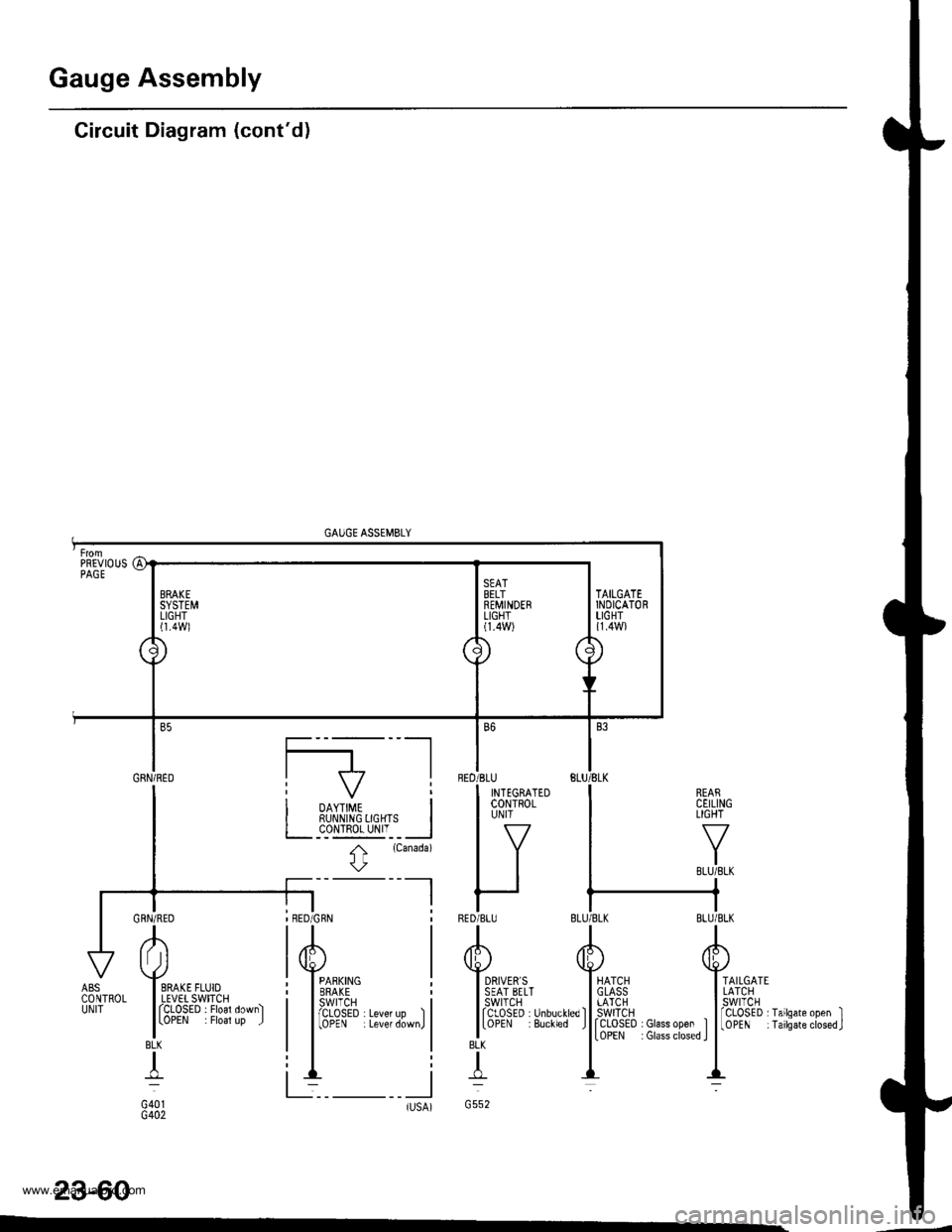
Gauge Assembly
Circuit Diagram (cont'd)
GAUGE ASSEMBLY
REARCEILINGLIGHT
TAILGATELATCHswtTcH
rCLOSED I Glass open ItoPEN : Glass closed I
fCLoSED rTailsate open II0PEN iTailsateclosed.J
23-60
BLK
T
G552tlsA)-
AI Jl
I SRAKE FLUIOI LEVET SWITCHI fCLOSED . Floal down)
lLoPEN . Floal up J
BLK
+
G401G402
ABSCONTROLUNIT
PREVIOUSPAGE
a1
\J
BRAKESYSTEMLIGHTl1.4Wl
\
./
SEATBELTREMINDERLIGHT(1.4W)
\/'
7\
\
TAILGATEINDICATORLIGHT{1.4W}
Gnru;neo I f7 |
I i oo,,#, i| | RUI\N|NG 0GHTS I
I L__c_o!l!g_yI'__l
I t
rcanada)
l\
-l I
BED
RED
B6
'BLU
I INTEGRATEDI coNTRoLI UN|T
lv
IItt
r-IBLU
www.emanualpro.com
Page 1252 of 1395
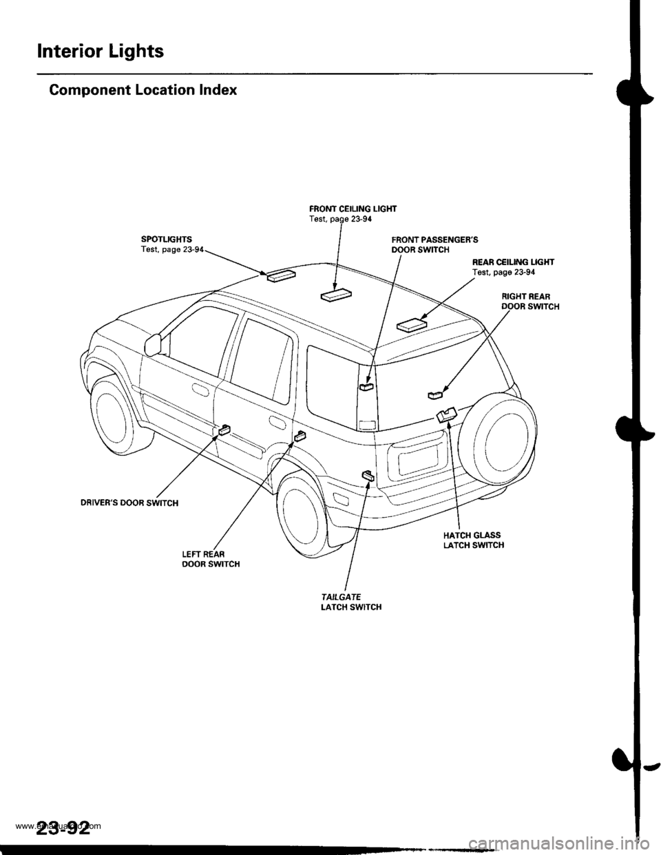
Interior Lights
Component Location Index
SPOTLIGHTSTest, page
DRIVER'S DOOR SWITCH
LEFT REARoooR swtTcH
FRONT CEILING LIGHTTest, page 23-94
FRONT PASSENGER'SDOOR SWITCH
REAR CCILING LIGI{TTest, page 23-94
RIGHT REARswtTcH
HATCH GLASSLATCH SWITCH
TAILGATELATCH SwlTCH
23-92
www.emanualpro.com
Page 1283 of 1395
![HONDA CR-V 2000 RD1-RD3 / 1.G Workshop Manual
Power Door Locks
Component Location lndex
DRIVERS DOOR L(rcK SWITCHTest, page 23-129
TRANSMITTERTest, page 23-130Cod6 Input Procedure,page 23-131
LOCK BUTTON
HATCH GLASS BUTTON
PA rc AUTTO]IIRIGT{T HONDA CR-V 2000 RD1-RD3 / 1.G Workshop Manual
Power Door Locks
Component Location lndex
DRIVERS DOOR L(rcK SWITCHTest, page 23-129
TRANSMITTERTest, page 23-130Cod6 Input Procedure,page 23-131
LOCK BUTTON
HATCH GLASS BUTTON
PA rc AUTTO]IIRIGT{T](/img/13/5778/w960_5778-1282.png)
Power Door Locks
Component Location lndex
DRIVER'S DOOR L(rcK SWITCHTest, page 23-129
TRANSMITTERTest, page 23-130Cod6 Input Procedure,page 23-131
LOCK BUTTON
HATCH GLASS BUTTON
PA rc AUTTO]IIRIGT{T REAR DOOR LOCKACTUATORTest, page 23-129Replacement,section 20
HATCH GLASS OPENER SOLENOIOfesl, page 23-122Replacem€nt. pago 23-122
FRONT PASSENGER'SDOOR LOCK ACTUATORTest, page 23-129R6Dlacement, soction 20
LEFT BEAR DOOR LOCKACTUATOBTesr, page 23-129Beplacement, section 20
. DRIVEB'S DOOR LOCKKNOB SW|TCHTesr, pag6 23-128. DRIVER'S DOOR LOCKACTUATORT6st, psge 23-128
-
23-123
www.emanualpro.com
Page 1285 of 1395
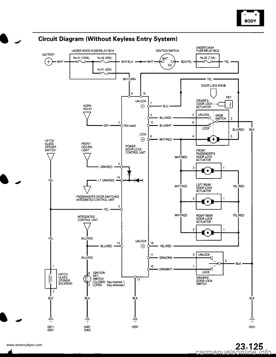
UNDER-DASHFUSE/RELAYBOX
Circuit Diagram {Without Keyless Entry System)
IGNTION SWITCHBATTEBY
@**'
FRONTCEILINGTIGHT
V
l_
r-
HATCHGLASSOPENERSWTCH
f7
I
l-J';
tr| oBtvERsI DOOn LOCKACTUATOR
s l-lLocx^l-Tq. l,, | -=tGJ--
+ II Locx IDRIVER'SD00R LOC(SWITCN
KNOB
6 tr.*;lwrr 3-K +wqr-t_t- BLKYEL
ffr
vEL
YEURED
GRNORN
GRNWHT
HORNRELAY
V
BLK
II
I:
G551
23-125
INTEGRATEDCONTROL UNIT
V
IBLU/RED
I
l- 8Lr
IBLU/RED
II
Iupl ,#. L?Vno'::iii^ ( li: ) swrTcHYAil''"',4,.'{yrcLosED
l' tottt
IBLK
II
I':
G()1G402
YEL
t/ |
tFl
?BLK
I
G6l1
UNDER.HOOD FUSEi RELAY 8OX
(Nol used)
LOCK
o
POWERDOOR LOCKCONTROL UNIT
EIGHT REAR00oR LocKACTUATOR
'tl
www.emanualpro.com