Set resume switch HONDA CR-V 2000 RD1-RD3 / 1.G Workshop Manual
[x] Cancel search | Manufacturer: HONDA, Model Year: 2000, Model line: CR-V, Model: HONDA CR-V 2000 RD1-RD3 / 1.GPages: 1395, PDF Size: 35.62 MB
Page 51 of 1395
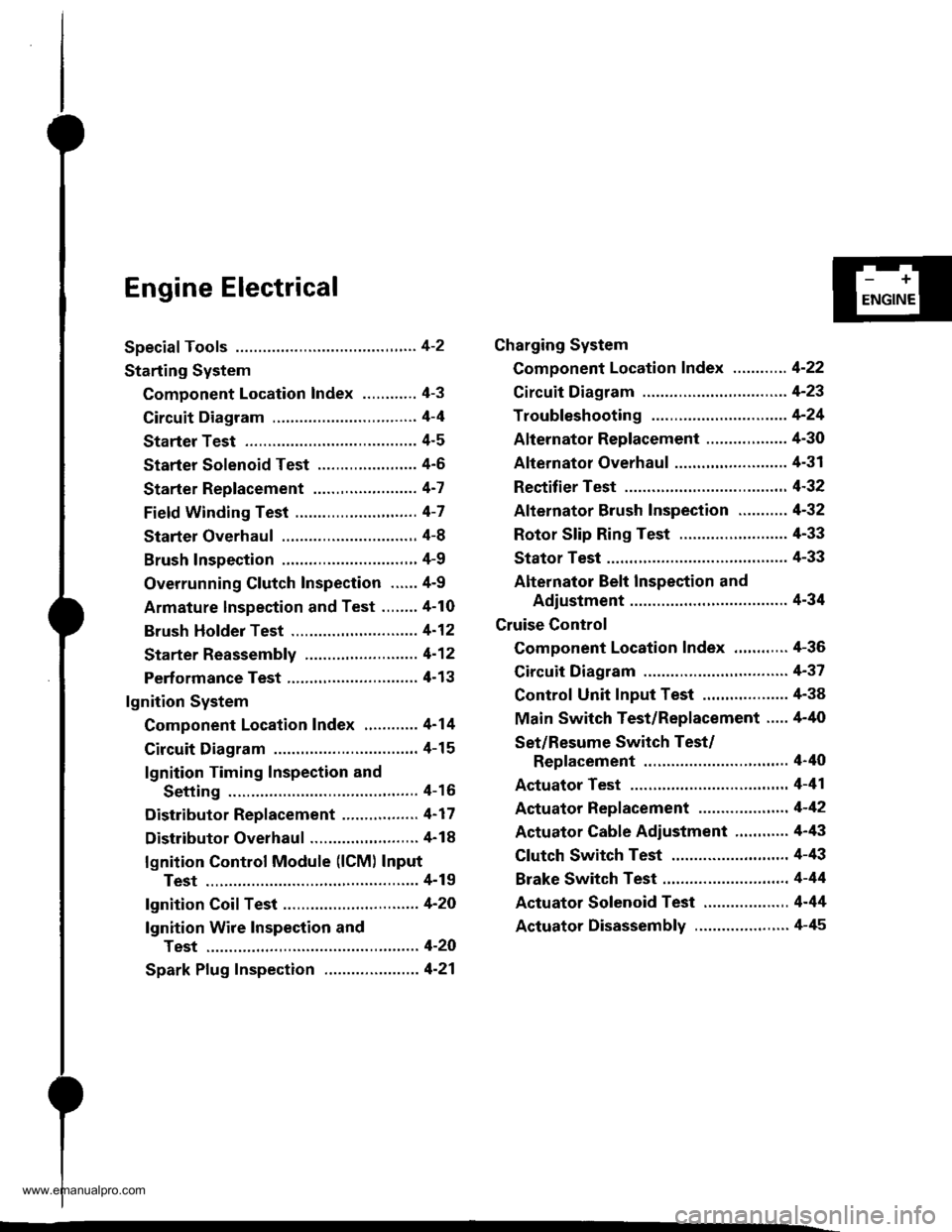
Engine Electrical
Speciaf Tools ............. 4-2
Starting System
Component Location Index ............ 4-3
Circuit Diagram ................................ 4-4
Starter Test ........... 4-5
Starter Solenoid Test ...................... 4'5
Starter Replacement ....................... 4-7
Field Winding Test ........................... 4-7
Starter Overhaul ............................,. 4-8
Brush Inspection ...........................,., 4-9
Overrunning Glutch Inspection ...... 4-9
Armature lnspection and Test ........4-10
Brush Holder Test ............................ 4-12
Starter Reassemb|y ......................... 4-1 2
Perf ormance Test ............................. 4- 1 3
lgnition System
Component Location Index ............ 4-14
Circuit Diagram ................................ 4-15
lgnition Timing Inspection and
Setting .......................................... 4-16
Distributor Replacement ........,........ 4-17
Distributor Overhaul .............,,......... 4-18
lgnition Control Module (lCM) Input
Test ..............................,................ 4-19
fgnition Coil Test .............................. 4-2O
lgnition Wire Inspection and
Test ............................................... 4-20
Spark Plug Inspection ..................... 4-21
-+
ENGINE
Charging System
Component Location Index ............ 4-22
Circuit Diagram ....................,........... 4-23
Troubleshooting .............................. 4-24
Alternator Replacement ..........,....... 4-30
Alternator Overhaul .......,,................ 4-31
Rectifier Test .........4-32
Alternator Brush Inspection ........... 4-32
Rotor Slip Ring Test ........................ 4-33
Stator Test ............. 4-33
Alternator Belt Inspection and
Adiustment ........4-34
Gruise Control
Component Location Index .,,,........ 4-36
Circuit Diagram ................................ 4-37
Control Unit Input Test ................... 4-38
Main Switch Test/Replacement ..... 4-40
Set/Resume Switch Test/
Replacement .......................,........ 4'40
Actuator Test ....,,., 4-41
Actuator Replacement ...............,.... 4-42
Actuator Cable Adiustment ............ 4-43
Clutch Switch Test .......................... 4-43
Brake Switch Test .................. .......... 4-44
Actuator Solenoid Test .............. ...,. 4-44
Actuator Disassembly ..................... 4-45
www.emanualpro.com
Page 86 of 1395
Gruise Control
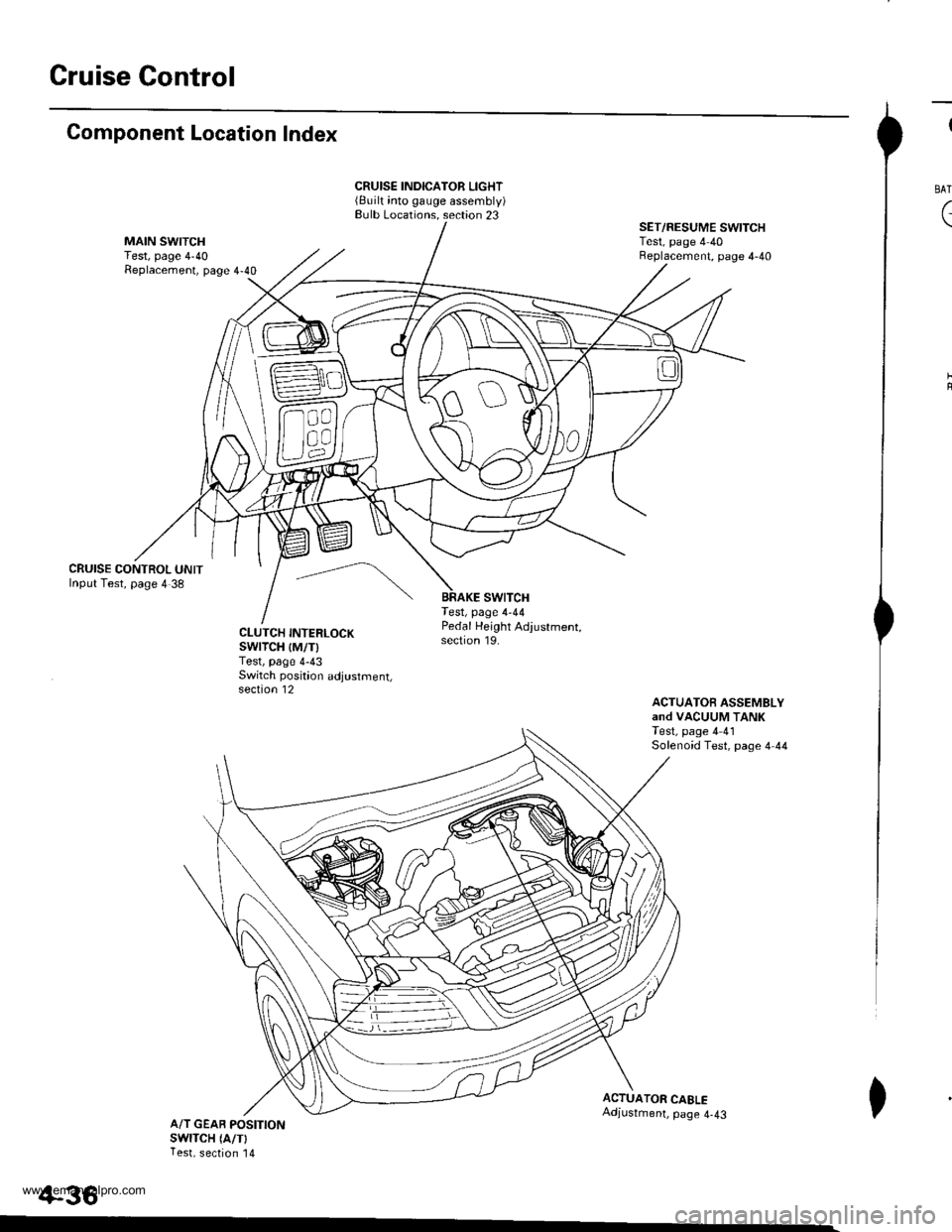
Component Location Index
CRUISE CONTROL UNITInput Test, page 4 38
CRUISE INDICATOR LIGHT(Built into gauge assembly)Bulb Locations. section 23
swtTcHTest, page 4-44
SET/RESUME SWITCHTest, page 4 40Beplacement, page 4-40
ACTUATOfi ASSEMBLYand VACUUM TANKTest, page 4 41Solenoid Test, page 4 44
CLUTCH INTERLOCKswrTcH {M/T)Test, page 4-43Switch poskion adjustment,section 12
Pedal Height Adjustment,section 19.
ACTUATOR CAELEAdjustment, page 4-43A/T GEAB POSITIONswlTcH (A/TlTest, section '14
+36
I
BAT
(
I
www.emanualpro.com
Page 89 of 1395

Disconnest the lilP connector from the control unit.
Csvity WireTest condition
R€conn€ct tho 14P connGctor to the control unit.
Test: Desired resultPossible cause it result is not obtained
BRNAr'VHTUnder all conditionsCheck for resistance to groundl
There should be 80 - 120 o.
Faulty actuator solenoid
Poor ground (G202)
An open in the wire1BRNUnder all conditionsCheck for resistance to groundl
There should be 40 - 60 0.
11BRN/BLKUnder all conditionsCheck for resistance to ground:
There should be 70 - 110 O.
2GRY
lgnition switch ON (ll),
main switch ON and
brake pedal depressed,
then released
Check for voltage to ground:
There should be 0 V with the pedal
depressed and battery voltage with
the pedal released.
. Faulty brake switch. An open in the wire
BLKUnder all conditionsCheck for continuity to ground:
There should be continuity.
. Poor ground (G401). An open in the wire
5GRNMHT
Brake pedal depressed,
then released
Check for voltage to ground:
There should be battery voltage with
the pedal depressed, and 0 V with
the pedal released.
Blown No.52 1'15 Alfuse in the
under-hood fuse/relay box
Faulty brake switch
An open in the wire
LT GRN/
RED
Set button pushedCheck for voltage to ground:
There should be battery voltage.Blown No. 52 {'15 A} fuse in the
under-hood fuse/relay box
Faulty horn relay
Faulty sevresume switch
Faulty cable reel
An open in the wire7LT GRN/
BLK
Resume button pushed
10RED/BLU
lgnition switch ON lll)Attach to ground:
Cruise indicator light in the gauge
assembly should come on.
Elown bulbBlown No. 25 (7.5 A) tuse in theunder-dash fuse/relay box
Faulty dimming circuit in the gauge
assembly
An open in the wire
ELU^r'r'HT
lgnitjon switch ON {ll}and main switch ON;
raise the front of the
vehicle, block one wheel
and rotate the other
wheel slowly.
Check for voltage between the
ELUA/VHT @ and BLK O terminalsl
There should be 0 - 5 V or more-0 - 5 V or more repeatedly.
Faulty vehicle speed sensor (VSS)
An open in the wire
r3LT GRN
lgnition switch ON {ll}and main switch ONCheck for voltage to ground:
There should be battery voltage.
Blown No. 14 (7.5 A) fuse in theunder-dash fuse/relay box
Faulty main switch
An open in the wire
l4PNK
A'/T: Shift lever in E, EotE
lvl/T: Clutch pedal
releaseo
Check for continuity to ground:
There should be continuity.NOTE: There should be no continu-
ity when the shift lever is in otherpositions or when the clutch pedal is
oepresseo.
Faulty A/f gear position switch 1A,/TlFaulty or misadjusted clutch switch
fi{/r)Poor ground (G101)
An open in the wire
BLU
Start tho engine. turnthe main switch ON, anddrive the vehicle over 25
mph (40 km/h)with the
crurse control set
Check for voltage to ground:
There should be approx.5 V
. Faulty cruise control unit. Shod to ground
*: '98 - 00 models with Automatic Transmission.
4-39
www.emanualpro.com
Page 90 of 1395
Cruise Control
1.
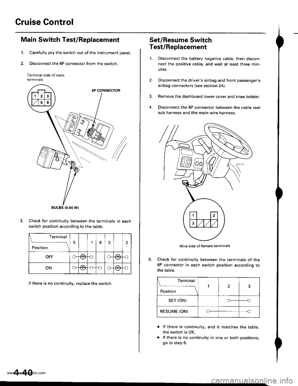
Main Switch Test/Replacement
Carefully pry the switch out of the instrument panel.
Disconnect the 6P connector from the switch,
Terminal side of malerermtnats
6P CONNECTOR
/
Check for continuitv between the terminals in each
switch position according to the table.
lf there is no continuity, replace the switch.
BULES {0.84 Wt
Terminal
;;;
-_\56
OFFG-@oG(9,{)
ONG@-oo-@-o
4-40
Set/Resume Switch
Test/Replacement
1.Disconnect the baftery negative cable, then discon-
nect the positive cable, and wait at least three min-
utes.
Disconnect the driver's airbag and front passenger's
airbag connectors (see section 24).
Remove the dashboard lower cover and knee bolster.
Disconnect the 6P connector between the cable reel
sub harness and the main wire harness.
4.
Wire side of temale terminals
Check for continuity
6P connector in each
the table.
between the terminals of the
switch position according to
Terminal
;;;
--_l2
SET (ON)o--o
RESUME (ON)Cf-c
a
lf there is continuity. and it matches the table,
the switch is OK.
lf there is no continuity in one or both positions,
go to step 6.
www.emanualpro.com
Page 91 of 1395
n-
n-
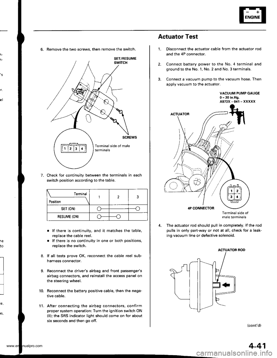
6. Remove the two screws. then remove the switch.
Check for continuity between the terminals in each
switch position according to the table.
. lf there is continuity, and it matches the table,
replace the cable reel.
. lf there is no continuity in one or both positions,
replace the switch.
lf all tests prove OK, reconnect the cable reel sub-
harness connector.
Reconnect the driver's airbag and front passenger's
airbag connectors, and reinstall the access panel on
the steering wheel.
Reconnect the battery positive cable. then the nega-
tive cable.
After connecting the airbag connectors, confirm
proper system operation: Turn the ignition switch ON
(ll); the SRS indicator light should come on for about
six seconds and then go off.
,s
r.
1e
to
7.
l
9.
10.
SET/RESUME
Terminal
t*,r*
-__\l23
SET ION)o----o
RESUME (ON)o----o
11.
4-41
1.
Actuator Test
Disconnect the actuator cable trom the actuator rod
and the 4P connector.
Connect battery power to the No. 4 terminal and
ground to the No. 1, No. 2 and No. 3 terminals,
Connect a vacuum pump to the vacuum hose. Then
apply vacuum to the actuator.
VACUUM PUMP GAUGE0-30 in.Hg.A973X-041-XXXXX
Terminalside otmale terminals
The actuator rod should pull in completely. lf the rod
pulls in only part-way or not at all, check for a leak-
ing vacuum Iine or defective solenoid.
ACTUATOB ROD
(cont'd)
www.emanualpro.com
Page 1313 of 1395
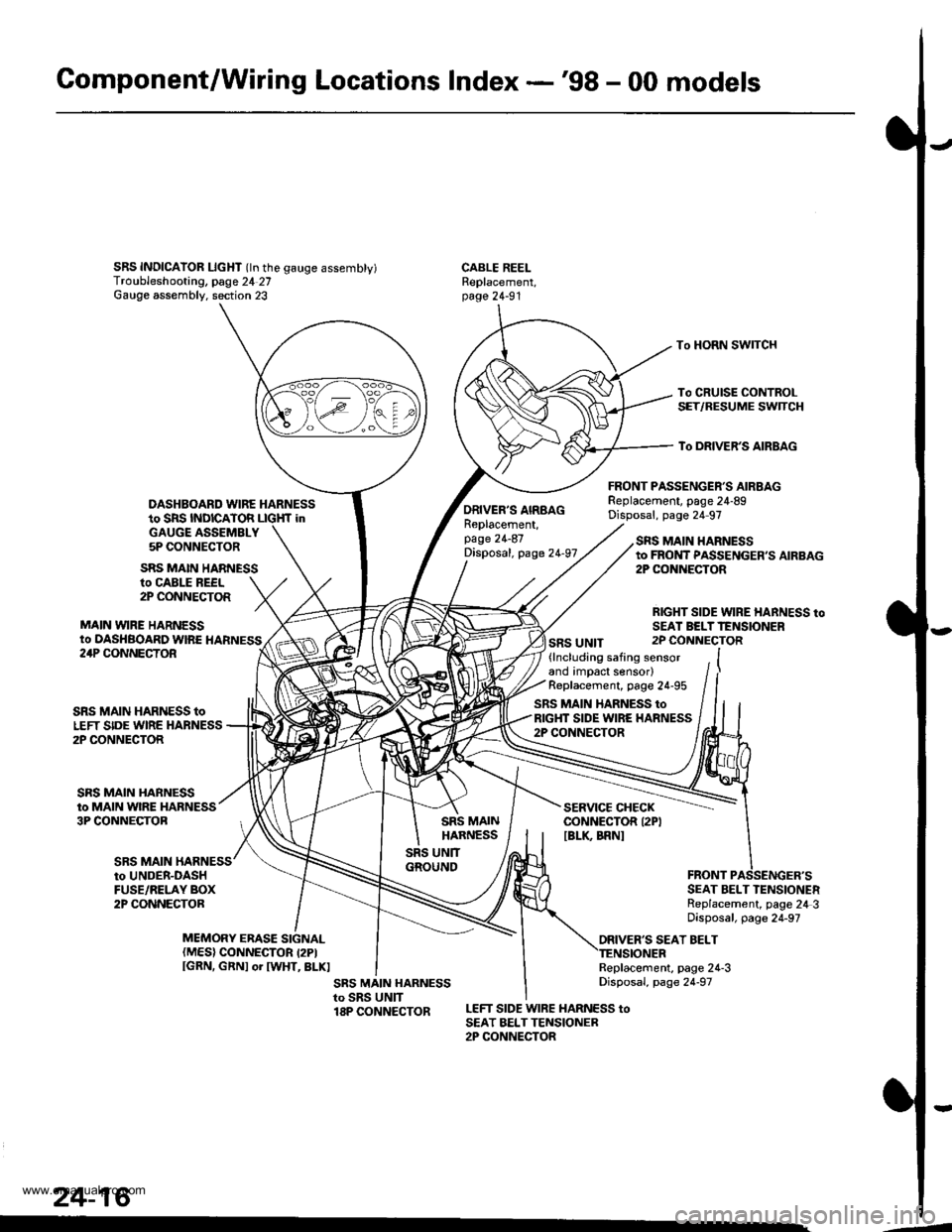
Gomponent/Wiring Locations Index -'98 - 00 models
SRS INDICAIOR LIcHT (ln the gauge assembty)Troubleshooting, page 24 27Gauge assembly. section 23
DASHBOARD WIRE HARNESSto SRS INDICATOR LIGHf inGAUGE ASSEMBLY5P CONNECTOR
FRONT PASSENGER'S AIRBAGReplacement, page 24-89Disposal, page 24 97
CABLE REELReplacement,page 24-91
To HORN SWITCH
To CRUISE CONTROLSET/RESUME SWTCH
To DRIVER'S AIRBAG
ro CABLE REEL2P CONNECTOR
MAIN VYIRE HARNESSto DASHBOARD WIRE HARNESS
SRS MAIN HARNESS
ORIVER'S AIRBAGReplacement,page 24-87Disposal, page 24-97
SRS UNIT
SRS MAIN HARNESSto FROI{T PASSENGER,S AIRBAG2P CONiIECTOR
RIGHT SIDE WIRE HARNESS toSEAI BELTTENSIONER2P CONNECTOR24P CONNECTOR
SRS MAIN
SRS MAIN HARNESS toLEFT SIDE WIRE HARNESS2P CONNECTOR
SRS MAIN HARNESSto MAIN WIRE HARNESS3P CONNECTOB
(lncluding safing sensorand impact sensor)Replacement, page 24-95
SRS MAIN HARNESS toRIGHT SIDE WIRE HARNESS2P CONNECTOR
SERVICE CHECKCONNECTOR I2PIIBLK BRNI
to UNDER-DASHFUSE/RELAY BOX2P CONNECTORSEAT BELT TENSIONERReplacement, page 24 3Disposal, page 24-97
ORIVER'S SEAT BELTMEMORY ERASE SIGNAL(MES) CONNECTOR I2PIIGRN, GRNI or IWHT, BLKIReplacement, page 24-3Disposal, page 24-97
LEFT SIDE WIRE HARNESS toSEAT BELTTENSIONER2P CONNECTOR
24-16
.4
www.emanualpro.com
Page 1389 of 1395
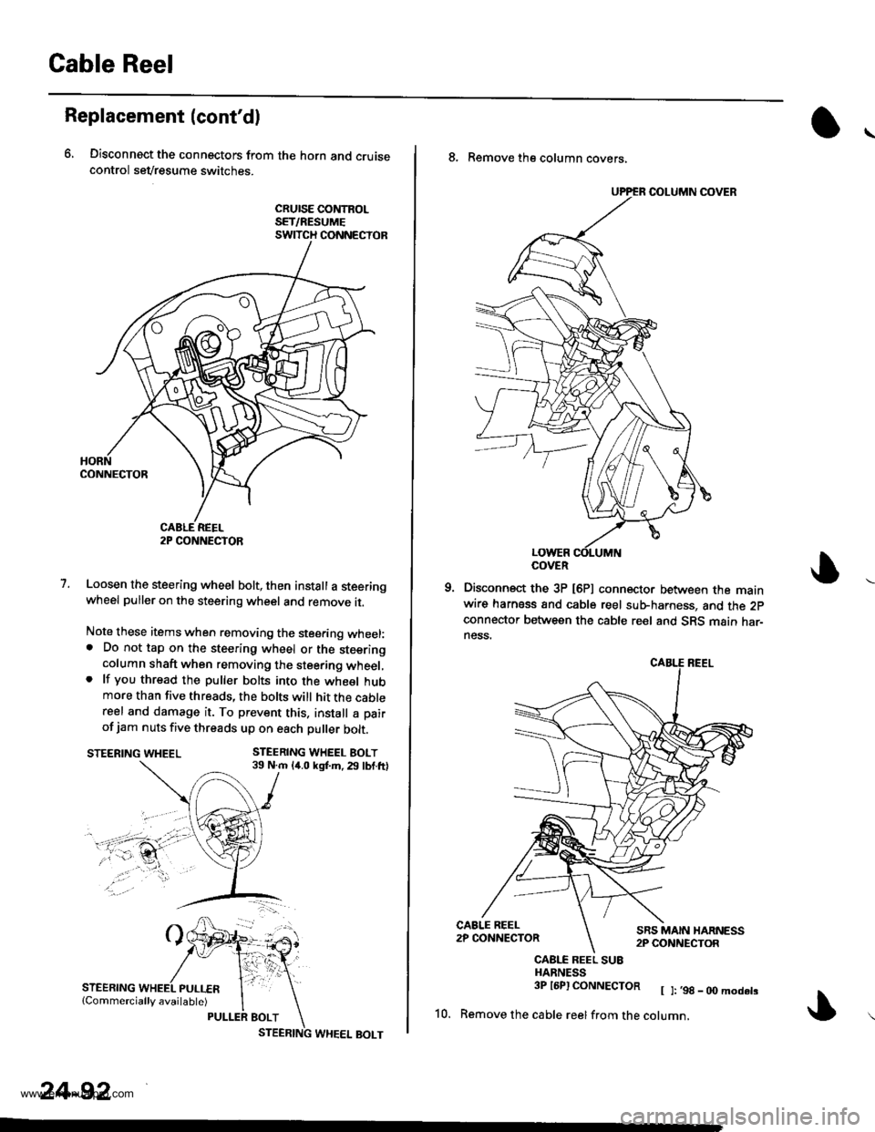
Gable Reel
Replacement (cont'dl
6, Disconnect the connectors from the horn and cruisecontrol sevresume switches.
cRursE coNtRoLSET/RESUMESWITCH CONNECTOR
1.Loosen the steering wheel bolt, then install a steeringwheel puller on the steering wheel and remove it.
Note these items when removing the stee.ing wheel:. Do not tap on the steering wheel or the steeringcolumn shaft when removing the steering wheel,. lf you thread the puller bolts into the wheel hubmore than five threads, the bolts will hit the cablereel and damage it. To prevent this. install a pair
of jam nuts five threads up on each puller bolt.
STEERING WHEEL BOLT39 N.m 14.0 kgf.m. 29 lbf.ftlSTEERING WHEEL
STEERING
2P CONNECTOR
24-92
8. Remove the column covers,
Disconnect the 3P [6P] connector between the mainwire harness and cable reel sub-harness, and the 2pconnector between the cable reel and SRS main har-ness.
CAALE REEL SU8HARNESS3P l6Pl CONNECTOR [ ]:,98_00modets
10. Remove the cable reelfrom the cotumn,
COVER
www.emanualpro.com