speedsensor HONDA CR-V 2000 RD1-RD3 / 1.G Workshop Manual
[x] Cancel search | Manufacturer: HONDA, Model Year: 2000, Model line: CR-V, Model: HONDA CR-V 2000 RD1-RD3 / 1.GPages: 1395, PDF Size: 35.62 MB
Page 206 of 1395
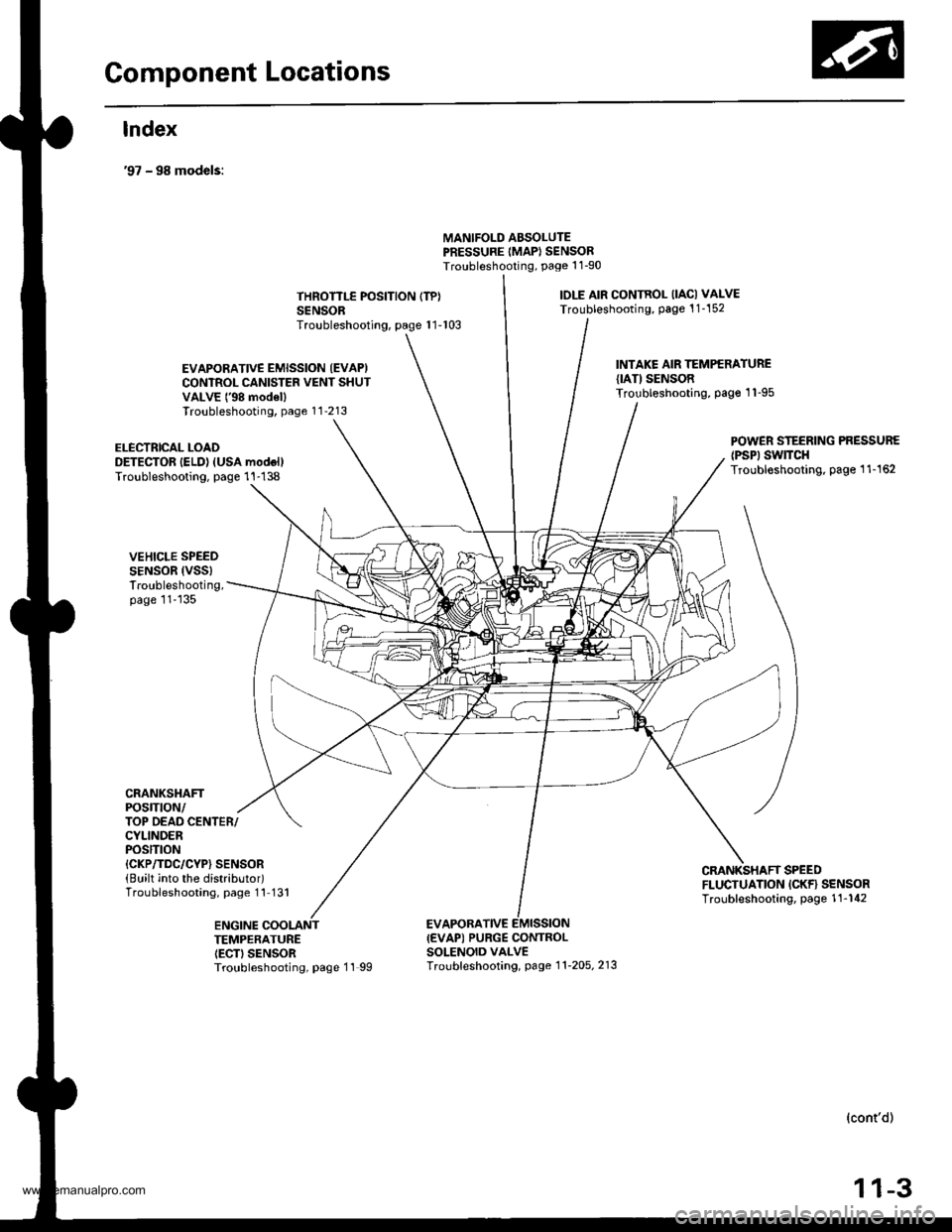
Component Locations
lndex
'97 - 98 models:
MANIFOLD ABSOLUTEPRESSURE IMAP} SENSORTroubleshooting, Page 1 1-90
THROTTLE POSITION (TP}
SENSORTroubleshooting, page 1 1-103
toLE AtR CONTROL llAcl VAI-VE
Troubleshooting, page 1 1-152
EVAPORATIVE EMISSION (EVAP)
CONTROL CANISTER VENT SHUTVALVE t'98 mod€llTroubleshooting, page 11'213
INTAKE AIR TEMPERATUREIIATI SENSORTroubleshooting. page 1 'l -95
ELECTRICAL LOADDETECTOR IELD) (USA modol)Troubleshooting, page 1 1-138
VEHICLE SPEEDSENSOR (VSS)
Troubleshooting,page 11'135
CRANKSHAFTPOSTTtON/
POWER STEERING PRESSURElPsPl swtrcHTroubloshooting, page 1 1-162
TOP OEAD CENTER/CYLINDERPOStTtON{CKP/TDC/CYP} SENSOR(Built into the distributor)Troubleshooting, page 1 l-131
CMNKSHAFT SPEEDFLUCTUATION ICKF} SENSORTroubleshooting. page 1'!-142
ENGINE COOLANTTEMPERATUREIECTI SENSORTroubleshooting, page 11 99
EVAPORATIVEI€VAP) PURGE CONTROLSOLENOID VALVETroubf eshooting, page 1 1'2o5, 213
(cont'd)
11-3
www.emanualpro.com
Page 207 of 1395
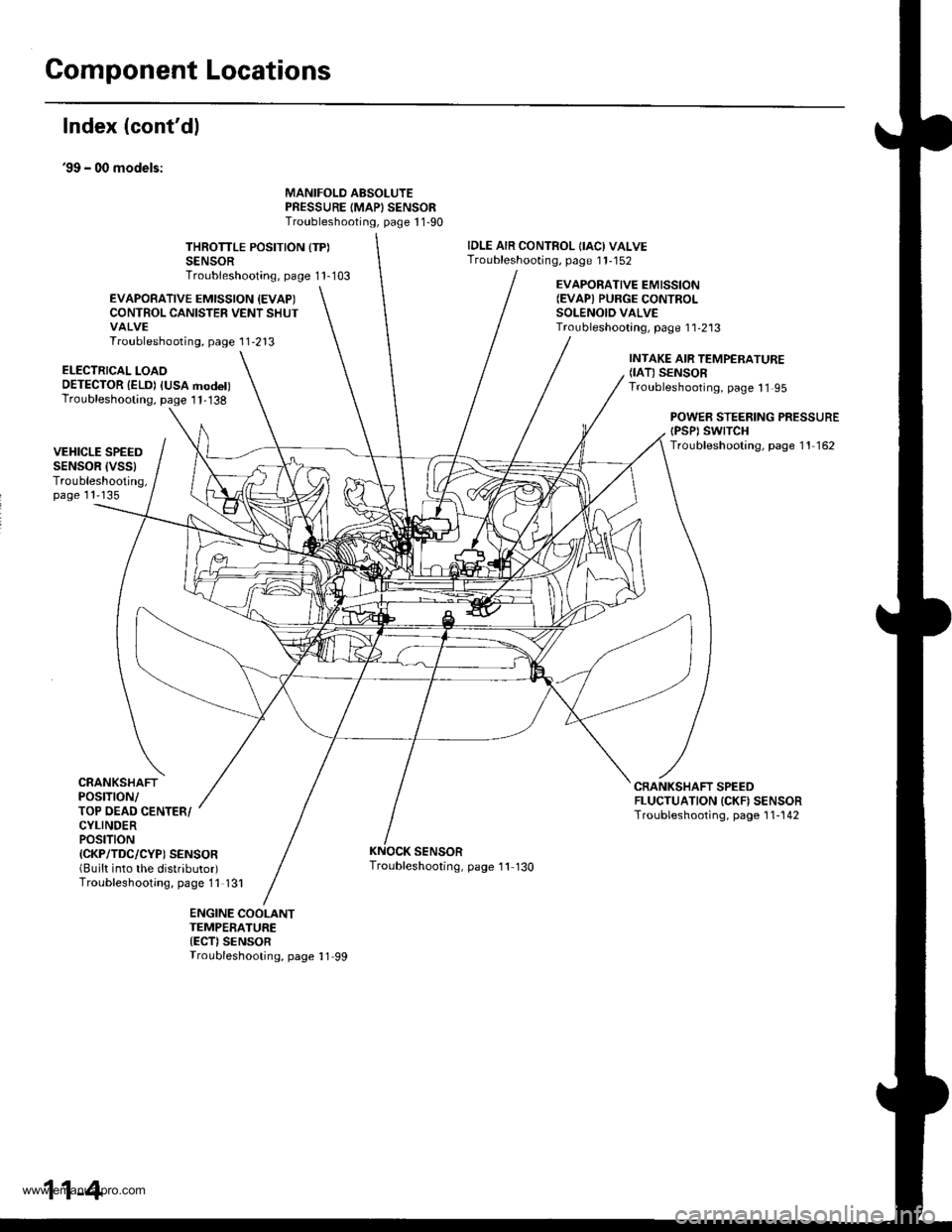
Component Locations
Index (cont'dl
39 - 00 models:
MANIFOLD ABSOLUTEPRESSURE IMAPISENSORTroubleshooting, page 1 1-90
THROTTLE POSITION {TP)SENSORTroubleshooting, page 1 1-103
IDLE AIR CONTROL OACI VALVETroubleshooting, page 1 1-152
EVAPOBATIVE EMISSION {EVAPICONTROL CANISTER VENT SHUTVALVETroubleshooting, page 1 1-213
EVAPORATIVE EMISSION(EVAPI PURGE CONTROI-SOLENOID VALVETroubleshootang, page 1 1-2'13
ELECTRICAL LOAOOETECTOR {ELD) IUSA modet)Troubleshooting, page I 1-138
INTAKE AIR TEMPERATURE(IAT) SENSORTroubleshooting, page 11 95
POWEB STEERING PRESSUREtPsPt swtTcHTroubleshooting, page 11 162VEHICLE SPEEDSENSOR IVSSITroubleshooting,page 11'135
CRANKSHAFTPOSTTTON/TOP OEAD CENTER/CYLINDERPOStTtON{CKP/TDC/CYP) SENSOR(Built into the distributor)Troubleshooting, page 11 131
CRANKSHAFT SPEEDFLUCTUATION ICKN SENSORTroubleshooting, page 1 1-142
SENSORTroubleshooting, page '11 130
ENGINE COOLANTTEMPERATURE{ECT)SENSORTroubleshooting, page 11 99
11-4
www.emanualpro.com
Page 228 of 1395
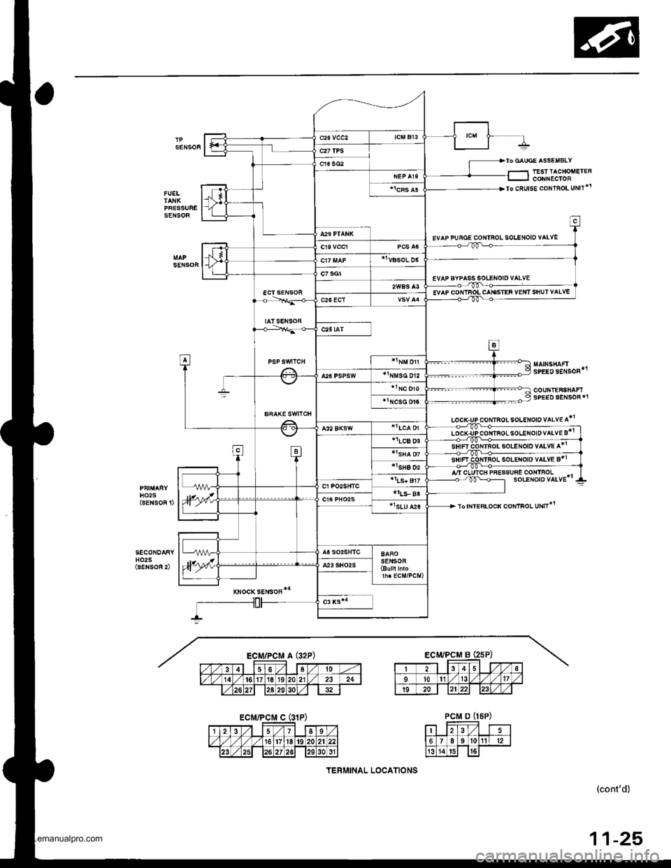
TANKPRESSUFESENSOF
TESTTACHOiIETERcoNr{EctoBlo CRUISE CoNTEOLUNIT+r
EVAPPURGE CONTROL SOIENOID VAIVE
sp:rosENsoF*1
COUNIERSHAFTSPEEDSENSOR'T
coNlRo! solENotD vALvE A*1
TO INTEFLOCK COI'TIFOL UNIT*!H02S(SENSOF 1)
rcrocrsgrson*'
(cont'd)
11-25
EVAP CONIFOL CANISTEF VETIT SHUTVALVE
TERI/lINAL LOCATIONS
www.emanualpro.com
Page 270 of 1395
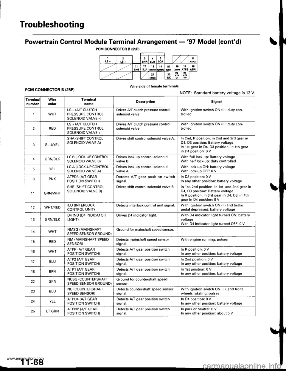
Troubleshooting
PCM CONNECTOR B I25PI
Powertrain Control Module Terminal Arrangement -'97 Model (cont'dl
Wire side of female terminalsPCM CONNECTOR B I25P}NOTE: Standard battery voltage is l2 V.
1 1-68L
TerminelnumbercolorTerminalnameOescriptionSignal
1LS 1A/T CLUTCHPRESSURE CONTROLSOLENOID VALVE -)
Drives A,/T clutch pressure controlsolenoid valveWith ignition switch ON (ll): duty con-trolled
2REDLS + (A"/T CLUTCHPRESSURE CONTROLSOLENOID VALVE +)
Drives A,/T clutch pressure controlsolenoid valveWith ignition switch ON (ll)r duty controlled
38LU//EL
SHA (SHIFT CONTROLSOLENOID VALVE A)Drives shift control solenoid valve A.In 2nd, R position. in 2nd and 3rd gear inD4, D3 position: Battery voltageIn lst gear in D4, D3 position, in 4th gear
in D4 position: 0 V
4GRN/BLKLC B (LOCK-UP CONTFOLSOLENOID VALVE B)Drives lock-up control solenoidvalve B,With full lock-up; Baftery voltageWith half lock-up: duty controlled
5YELLC A (LOCK.UP CONTROLSOLENOID VALVE A)Drives lock-up control solenoidWith lock'up ON: battery voltageWith lock-up OFF:0 V
IPNKATPD3 (Ay'T GEARPOSITION SWITCH}Detects A/T gear position switchsignal. _
In D3 position:0 Vln any other position: battery voltage
11GRN/VVHT
SHB (SHIFT CONTROLSOLENOID VALVE 8}Drives shift control solenoid valve B.In 1st, 2nd position, in 1st and 2nd gear inD4, D3 position: Battery voltageIn R position, ;n 3rd gear in 04, D3, in 4thgear in D4 position: 0 V
12WHT/BEDILU (INTERLOCK
CONTROL UNITiDetects interlock control unh signal.With ignition switch ON (ll)and brakepedal depressed: battery voltage
GRN/BLKD4IND (04 INDICATORLIGHT}Drives Dl indicator light.With D4 indicator light turned ON: batteryvoltageWith D4 indicator light turned OFF: 0 V
14NMSG (MAINSHAFT
SPEED SENSOR GROUND}Ground tor mainshaft speed sensor.
REDNM (MAINSHAFT SPEEDSENSOR)Detects mainshaft speed sensorsrgnal,With engine running: pulses
16ATPR (A"/T GEARPOSITION SWITCH)Detects A/T gear position switchsrgnal.InRposition:0VIn any other position: battery voltage
1'lBLUATP2 (A./T GEARPOSITION SWITCH)Detects A/T gear position switchsrg nal,In 2nd position: 0 VIn any other position: battery voltage
18BRNATP1 (4,,/T GEARPOSTTTON SWTTCH)Detects A/T gear position switchsrg nal,ln lst position: 0 VIn any other position: battery voltage
22GBNNCSG (COUNTERSHAFT
SPEED SENSOR GROUND)Ground tor countershaft speedsensor,
23BLUNC (COUNTERSHAFT
SPEED SENSOR)Detects countershaft speed sensorsrgnal.With agnition switch ON (ll), and lrontwheels rotating: pulses
24YELATPD4 (M GEARPOSITION SWITCH)Detects A,/T gear position switchsrgnal.In D4 positionr 0 VIn any other position: battery voltage
25LT GRNATPNP {A/T GEARPOSITION SWITCH)Detects A/T gear position switchsignal.In park or neutral:0 VIn any other position: about 5 V
www.emanualpro.com
Page 271 of 1395
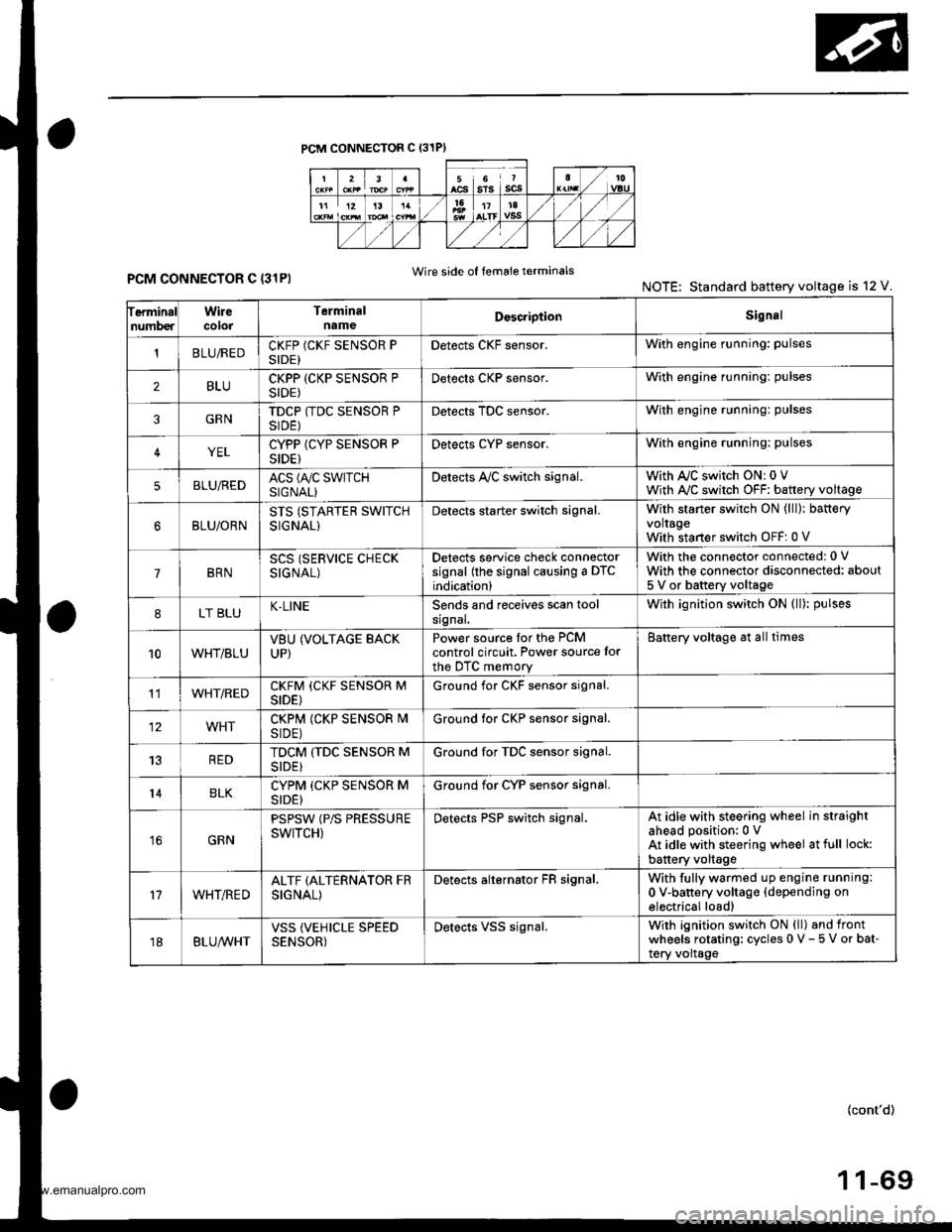
PCM CONNECTOR C (31PI
ferminalnumberWirecolorTerminalnameDoscriptionSignal
'tBLUiREDCKFP (CKF SENSOR PSIDE)Detects CKF sensor.With engine running: pulses
2BLUCKPP (CKP SENSOR PSIDE)Detects CKP sensor.With engine running: pulses
3GRNTDCP (TDC SENSOR PSIDE)Detects TDC sensor.With engine running: pulses
4YELCYPP (CYP SENSOR PSIDE)Detects cYP sensor.With engine running: pulses
5BLU,frEDACS (A/C SWTTCHSIGNAL)Detects A,/C switch signal.With AJC switch ON: 0 VWith A,/C switch OFF: battery voltage
BLU/ORNSTS (STARTER SWITCHSIGNAL)
Detects starter switch signal.With starter switch ON (lll): bafteryvoltageWith staner switch OFF: 0 V
7BRNSCS (SERVICE CHECKSIGNAL)
Detects service check connectorsignal (the signal causing a DTCindication)
With the connector connected: 0 V
With the connector disconnected: about
5 V or battery voltage
8LT BLUK-LINESends and receives scan toolsrgnal.With ignition switch ON (ll): pulses
10WHT/BLUVBUUP)
(VOLTAGE BACKPower source tor the PCMcontrol circuit. Power source for
the DTC memory
Battery voltage at all times
11WHT/REDCKFM (CKF SENSOR MSIDE)Ground for CKF sensor signal.
12WHTCKPM (CKP SENSOR I\4SIDE)Ground lor CKP sensor signal.
13REDTDCM (TDC SENSOR MSIDE}Ground for TDC sensor signal.
14BLKCYPM (CKP SENSOR MSIDE}Ground for CYP sensor signal.
16GRN
PSPSW (P/S PRESSUREswtTcH)Detects PSP switch signal.At idle with steering wheel in straightahead position:0 VAt idle with steering wheel at full lock:
battery voltage
17WHT/REDALTF (ALTERNATOR FRSIGNAL)
Detects alternator FR signal.With fully warmed up engine running:
0 V-battery voltage {depending onelectrical load)
18BLUA/VHTVSS (VEHICLE SPEEDSENSOR)Detects VSS signal.Wirh ignition switch ON (ll) and frontwheels rotating: cycles 0 V - 5 V or bat-tery voltage
Wire side of femaie terminalsPCM CONNECTOR C {31PINOTE: Standard battery voltage is 12 V.
(cont'd)
www.emanualpro.com
Page 276 of 1395
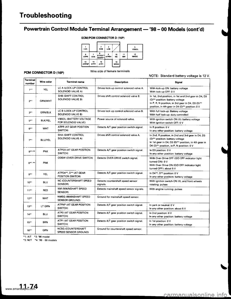
Troubleshooting
Powertrain Control Module Terminal Arrangement -'98 - 00 Models (cont'dl
PCM CONNECTOR D (16P)NOTE: Standard battery voltage is 12 V.
i1:A/T *3:'98 model'2: M/T *4:'99 00 models
ECM/PCM CONNECTOR D {16P}
Wire side of lemaleterminals
D€s4riptionSign!l
YELLC A {LOCK,UP CONTBOLSOLENOID VALVE A)Oriv€s lock'up conrrol solenoid valve A.With lock-up ON: b6ttery voltagsWith lock-up OFF:0 V
2+1GBN,M/HT
SHB (SHIFT CONTROLSOLENOIO VALVE B)Drives shift controlsolenoid valve B.In 1st, 2nd position, in lst and 2nd gear an D4, D3(D)11 position: battery vohag€In P, R, N position, in 3rd geaf in D1, D3 (D)*.position, in 4th gear in D4 (D)*r positionr0 V
GRN/BLKLC 8 (LOCK,UP CONTROLSOLENOID VALVE B}Drives lock up controlsolenoid valve B.With full lock-up: 8attery voitageWith half lock'uprduty controlled
BLK/YELVBSOL (BATTERY VOLTAGEFOR SOLENOID VALVE}Pow€r source of solenoid valvs.With ignition switch ON (ll): batteryvoltageWith ignition switch OFF| 0 V
ATPR {AI GEAE POSITIONSWITCH)Delscls A/T gear posrtion swirch srgnal.In any other positjon: battsry voltage
BLU,ryEL
SHA (SHIFT CONTROLSOLENOID VALVE A)Drives shift conrrol solenoid valvp A.In 2nd, R position, an 2nd and 3rd ge6r in D4, D3(D)r' posilion: batlery voltageIn 1st gear in 04, 03 {D)}. position, in 4th gear inD4 (D)*. position, in P, N position:0 V
PNKATPD3 (AT GEAR POSITIONswrTcH)Detects A,/T g€ar poshion swirch sign6l.In D3 position:0 Vh any other posiiion: ban€ryvoltage
PNK
ODSW (OVER.DBIVE SWITCH)Detects OVEF-DRIVE swirch sagnal.With Ovor Drivs OFF (O/D OFF indicator lightturned ON): 0 VWilh Ovsr Drivs ON (O/D OFF indicrto.lashtturned OFF): about 5 V
9''YELATPDI}3, O}I {AT GEARPOStTtON SWTTCH)Dot€cts A/T g€ar position swirch signal.In D4r3, O*. position:0 VIn any other posilion: battery voltage
10.,BLUNC (COUNIERSHAFT SPEEDSENSOR)Detscts counl€rshaft speed sensorWith ignition switch ON (ll), and ffonr wheels
REDNM IIVAINSHAFT SPEEDSENSOB)Detects mainshaft speed sensor sign6ls.Wilh engine running: pulses
NMSG {MAINSHAFTSPEEDSENSOB GBOUND)Ground for mainshaft speed sensor-
'13*1LT GRNATPNP (AT GEAR POSITIONswtTcH)Delects A,/T gear position switch signat.In park or n€utral:0 Vh any other posilion: about 5 V
8LUATP2 (AT GEAR POSFIONswrTcH)Dstects A,/T gear position switch signal.h any othsr position: battery voltsgs
15.'BRNATP1 {AT GEAR POSITIONswrTcH)Detscts A/T gear position switch signal.In any other position: htteryvoltage
t6''GRNNCSG {COUNTERSHAFTSPEED SENSOR GROUND}Grouod for counterchaft sp€ed s€nsor.
11-74
www.emanualpro.com
Page 279 of 1395
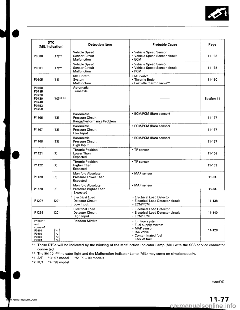
DTC(MlL indicationlDotection ltomProbable CausePage
P0500 t17)*,
Vehicle SpeedSensor CircuitMalfunction
Vehicle Speed SensorVehicle Speed Sensor circu itECtVI1 1-135
P0501 l17J*1
Vehicle SpeedSensor CircuitMalfunction
Vehicle Speed SensorVehicle Speed Sensor circuitPCM11-135
P0505 (14)ldle ControlSystemMalfunction
IAC valveThrottle BodyFast idle thermo valve*11 '�]- 150
P0700P0715PO720P0730P0740P0753P0758
AutomaticTransaxle
Section l4
P1106 (13)BarometricPressure CircuitRange/Performance Problem
ECM/PCM (Baro sensor)
11-137
P1107 (13)BarometricPressure CircuitLow InPut
. ECM/PCM {Baro sensor)11-137
P1108 (13)BarometricPressure CircuitHigh Inpur
ECM/PCM {Baro sensor)11,137
P1121 (7)Throttle PositionLower ThanExpected
. TP sensor11-109
P1122 (7)Throttle PositionHigher ThanExpected
' TP sensor1 1-'109
P112a (5)Manifold AbsolutePressure Lower ThanExpected
. MAP sensor11-94
P1129 (5)Manifold AbsolutePressure HiqherThanExpected
' MAP sensor1l-94
P1297 (20)Electrical LoadDetector CircuitLow Input
Electrical Load DetectorElectrical Load Detector circuitECM/PCM1 1- 138
P1298 (20)Electrical LoadDetector CircuitHigh Input
Electrical Load DetectorElectrical Load Detector circuitECM/PCM11-140
P1300'3
P0301P0302P0303P0304
7l721314
Random lvlisfirelgnition systemFuel supply systemMAP sensorIAC valveContaminated fuelLack offuel
11-126
*: These DTCS will be indicated by the blinking of the Malfunction Indicator Lamp {MlL} with the SCS service connector
connected.**:The E (E])+s indicator light and the Malfunction Indicator Lamp (MlL) may come on simultaneously.*1:A,./T "3: '97 model +5: '99 - 00 models*2: M/T *4:'98 model
{cont'd)
11-77
www.emanualpro.com
Page 531 of 1395
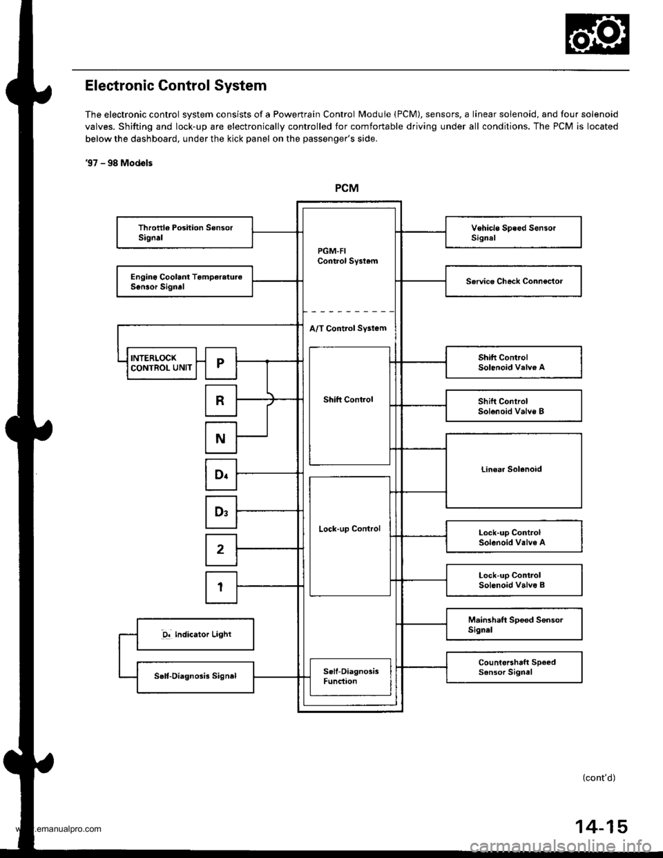
Electronic Control System
The electronic control svstem consists of a Powertrain Control Module (PCM), sensors, a linear solenoid, and four solenoid
valves. Shifting and lock-up are electronically controlled for comfortable driving under all conditions. The PCM is located
below the dashboard, under the kick panel on the passenger's side.
'97 - 98 Mod€ls
PGM.FIControl Sy3t6m
Throttl€ Poshion SensorSignalVehicle Sp.ed SensorSignal
Engino Coolant TamperetureService Check connectorSonsor Signrl
A/T Control Sy3tem
INTERLOCK
Shift Cont.ol
Shift ControlSolenoid valve ACONTROL UNITr
RShift ControlSolenoid Valve B
N
Linear SolenoidDr
Lock-up Control
Ds
Lock-up ControlSolenoid Valve A2
Lock-up ConirolSol6noid valvo B1
M.inshaft Spoed SensorSignel-D! Indicator Light
Count€rahaft Speedsensor SignelSelt-Oiagnosb signel
I
Sell-DiagnosisFunction
l-
{cont'd)
14-15
www.emanualpro.com
Page 532 of 1395
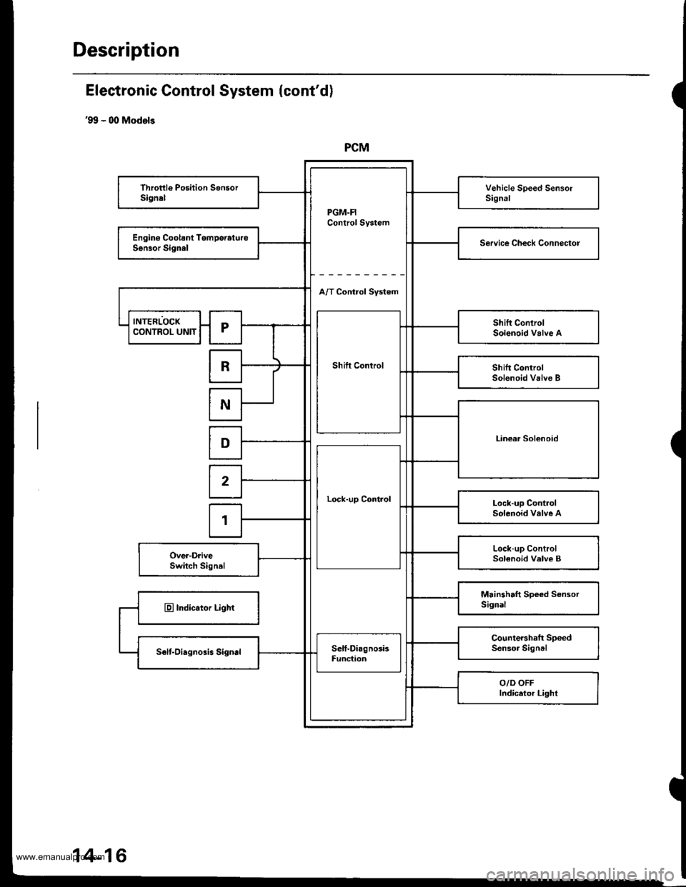
Description
PCM
PGM.FIControl System
Throttle Position SensorSignelVehicle Speed SensorSignal
Engin€ Coolsnt TomperatureSen30r SignalService Ch€ck Connectol
A/T Control Svstem
INTERLOCK
Shift Control
Shift ConlrolSolenoid Valve ACONTROL UNITr
RShift ControlSolenoid Valve B
N
Linear SolenoidD
Lock-up Control
2
Lock-up ControlSolenoid valve A1
Lock-up ControlSolenoid Valve BOver-DriveSwitch Signal
Mainshaft Speed SensorSignalE Indicator Light
Countershaft SpeedSensor SigntlSelt-Oiagnosis SigndSelf-DiagnosisFunc{ion
O/D OFFIndicetor Light
Electronic Gontrol System (cont'd)
'99 - 00 Models
14-16
www.emanualpro.com
Page 567 of 1395
![HONDA CR-V 2000 RD1-RD3 / 1.G Workshop Manual
NIEFIOCX CONTAOLI]N T
KEYLOCX SH FILOCKACC PUSN SW SOLEIOLO 6] SOLENO1O PPINSW ILU ATP P GNO
SPEEDSENSOR
V
I
t-
JFj
IgLUA|/HI
IIIBLl(BLU
I___L
V
PosrTroN
PPOSITON
I
I
t_
,T
llYEUBLX WN I/8LI< V
HONDA CR-V 2000 RD1-RD3 / 1.G Workshop Manual
NIEFIOCX CONTAOLI]N T
KEYLOCX SH FILOCKACC PUSN SW SOLEIOLO 6] SOLENO1O PPINSW ILU ATP P GNO
SPEEDSENSOR
V
I
t-
JFj
IgLUA|/HI
IIIBLl(BLU
I___L
V
PosrTroN
PPOSITON
I
I
t_
,T
llYEUBLX WN I/8LI< V](/img/13/5778/w960_5778-566.png)
NIEFIOCX CONTAOLI]N T
KEYLOCX SH FILOCKACC PUSN SW SOLEIOLO 6] SOLENO1O PPINSW ILU ATP P GNO
SPEEDSENSOR
V
I
t-
JFj
IgLUA|/H'I
I'IIBLl(BLU
I___L
V
PosrTroN
PPOSITON
I'
I
t_
,T
l'l'YEUBLX WN I/8LI< V
T-T
llYEL]BLK WHTELK
l,l
IH q**
lF I l:$"."-T- LI s"'n Locr erx v
lS0LEN00 |vrL 4
__t ;,
--l
l
I
I
BqN€LK
I
Gr01
SERVCECHECXCONNECTOF
l*BFN
I-T-
I
BLK
T
,l
Tl'BLU/YEL GFNAiI/N]
ll
t*l I
t?tLI SN FT CONTFOLI SOLENOIDVALVE
I
AssEM4Y
I-:
COTJNIEFSHAfI LNEAFSOLEI€DSPEEDSENSOA
www.emanualpro.com