wheel hub HONDA CR-V 2000 RD1-RD3 / 1.G Workshop Manual
[x] Cancel search | Manufacturer: HONDA, Model Year: 2000, Model line: CR-V, Model: HONDA CR-V 2000 RD1-RD3 / 1.GPages: 1395, PDF Size: 35.62 MB
Page 525 of 1395
2.
L
E Position
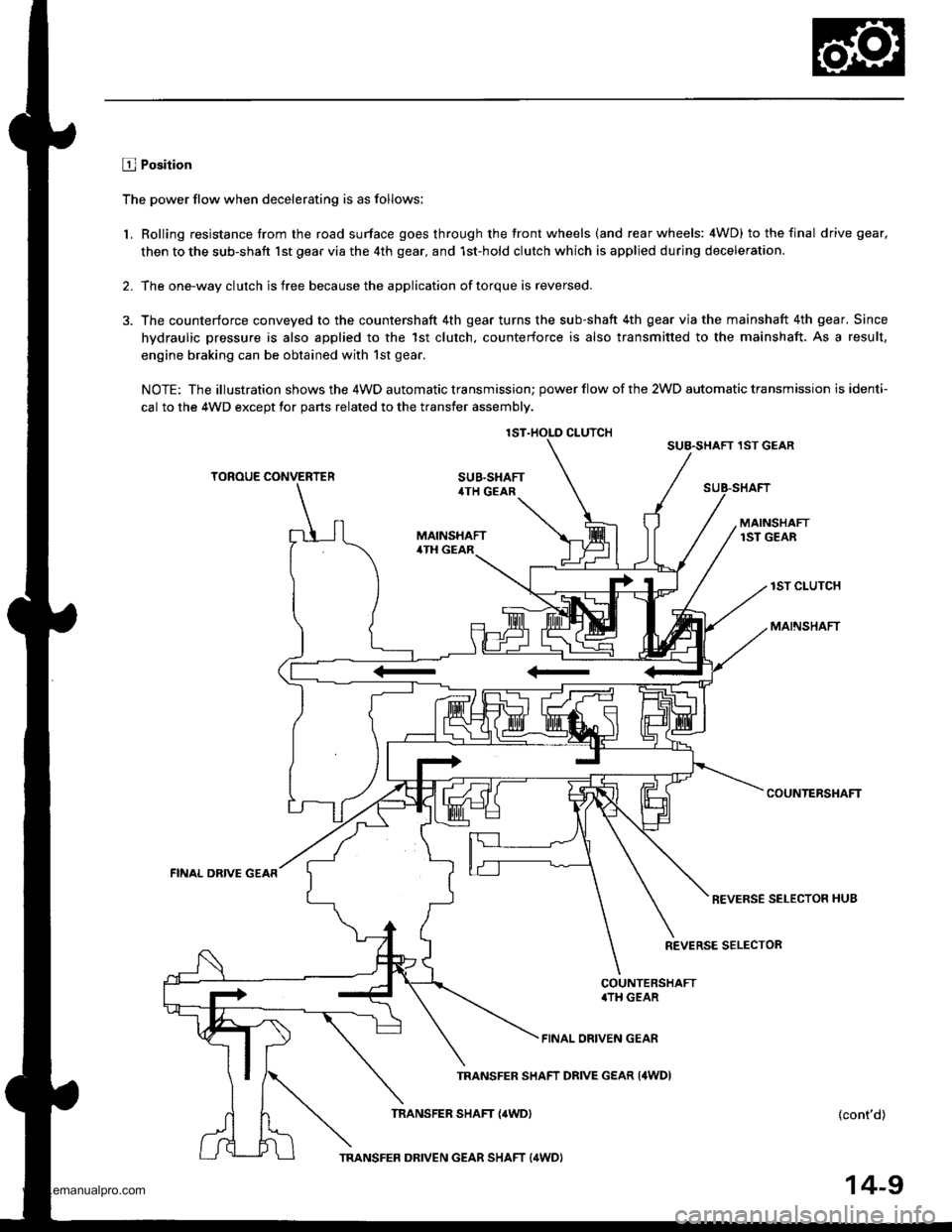
The power flow when decelerating is as follows:
Rolling resistance trom the road surface goes through the tront wheels (and rear wheels: 4WD) to the final drive gear.
then to the sub-shaft lst gear via the 4th gear. and 1st-hold clutch which is applied during deceleration.
The one-way clutch is free because the application of torque is reversed.
The counterforce conveyed to the countershaft 4th gear turns the sub-shaft 4th gear via the mainshaft 4th gear. Since
hydraulic pressure is also applied to the 1st clutch. counterforce is also transmitted to the mainshaft. As a result,
engine braking can be obtained with'lst gear.
NOTE: The illustration shows the 4WD automatic transmission; power flow of the 2WD automatic transmission is identi-
cal to the 4WD except tor parts related to the transfer assembly.
J.
SUB.SHAFT 1ST GEAR
TOROUE CONVERTER
FINAL DRIVE GEAR
SUB.SHAFT{TH GEAR
MAINSHAFTlST GEAR
lST CLUTCH
MAINSHAFT
COUNTERSHAFT
REVERSE SELECTOR HUB
REVERSE SELECTOR
COUNTERSHAFTIITH GEAR
FINAL ORIVEN GEAR
TRANSFER SHAFT DRIVE GEAR {4WDI
TRANSFEB SHAFT {{WD){cont'd}
lST.HOLD CLUTCH
TRANSFER DRIVEN GEAR SHAFT {,lWDl
14-9
www.emanualpro.com
Page 671 of 1395
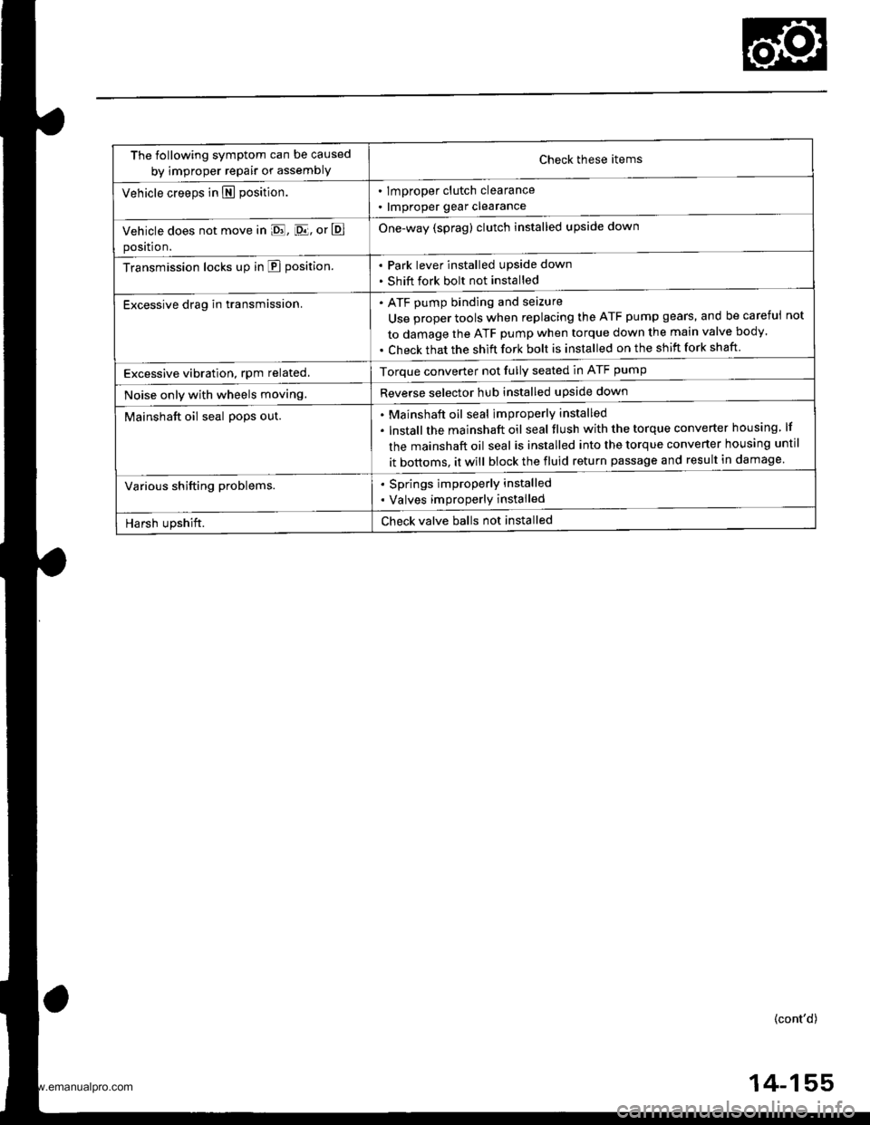
The following symptom can be caused
by improper repair or assemblYCheck these items
. lmproper clutch clearance
. lmproper gear clearance
One-way (sprag) clutch installed upside down
Park lever installed upside down
Shift fork bolt not installed
Vehicle creeps in N position.
Vehicle does not move in E, [D.lj, or E
position.
Transmission locks up in E position.
Excessive drag in transmission.ATF pump binding and seizure
Use proper tools when replacing the ATF pump gears, and be careful
to damage the ATF pump when torque down the main valve body.
Check that the shift fork bolt is installed on the shift fork shaft
not
Excessive vibration, rpm related.Torque converter not fully seated in ATF pump
Reverse selector hub installed upside downNoise only with wheels moving.
Mainshaft oil seal po9s out.Mainshaft oil seal improperly installed
lnstallthe mainshaft oil seal tlush with the torque converter housing lf
the mainshaft oil seal is installed into the torque converter housing until
it bottoms. it will block the fluid return passage and result in damage
Various shifting problems.. Springs improperly installed
. Valves improperly installed
Harsh upshift.Check valve balls not installed
(cont'd)
4-155
www.emanualpro.com
Page 794 of 1395

Description
Rear Differential
Outline
The Real-time 4WD-Dual Pump System model has a hydraulic clutch and a differential mechanism in the rear differential
assembly. Under normal conditions, the vehicle is driven by the front wheels. However, depending on to the driving force
of the front wheels and the road conditions. the system instantly transmits appropriate driving force to the rear wheels
without requiring the driver to switch between 2WD (tront wheel drive) and 4WD (four wheel drive). The switching mecha-
nism between 2WD and 4WD is integrated into the rear differential assembly to make the system light and compact.
ln addition, the dual-pump system switches off the rear-wheel-drive force when braking in a forward gear. This allows the
braking system to work properly on models equipped with an Anti-lock Braking System (ABS).
Construction
The rear differential assembly consists of the torque control differential case assembly and the rear differential carrier
assembly. The torque control differential case assembly consists of the differential clutch assembly, the companion
flange, and the oil pump body assembly. The rear differential carrier assembly consists of the differential mechanism. The
differential drive and driven gears are hypoid gears.
The oil pump body assembly consists of the front oil pump, the rear oil pump, the hydraulic control mechanism, and the
clutch piston. The clutch piston has a disc spring that constantly provides the differential clutch assembly with a preset
torque to Drevent abnormal sound.
The clutch guide in the differential clutch assembly is connected to the propeller shaft via the companion flange, and it
receives the driving force lrom the transfer assembly. The clutch guide rotates the clutch plate and the front oil pump in
the oil pump body.
The clutch hub in the differential clutch assembly has a clutch disc that is splined with the hypoid drive pinion gear. The
hypoid drive gear drives the rear oil pump.
The front and rear oil pumps are trochoidal pumps. The rear oil pump capacity is 2.5 percent larger that the front oil pump
to handle the rotation difference between the front and rear wheels caused by worn front tires and tight corner braking.
The oil pumps are designed so the fluid intake works as a fluid discharge when the oil pumps rotate in reverse. Genuine
Honda CVT fluid is used instead of differential fluid.
Operation
When there is a difference in rotation speed between the front wheels (clutch guide) and rear wheels (hypoid driven gear),
hydraulic pressure from the front and rear oil pumps engages the differential clutch, and drive force from the transler
assembly is applied to the rear wheels.
The hydraulic pressure control mechanism in the oil pump body selects 4WD mode when the vehicle is started abruptly,
or when accelerating in a forward or reverse gear (causing rotation difference between the front and rear wheels). or
when braking in reverse gear {when decelerating). lt switches to 2WD mode when the vehicle is driven at a constant speed
in forwar! or reverse gear (when there is no rotation difference between the front and rear wheels), or when braking in a
fo rwa rd gear (when decelerating).
To protect the system, the differential clutch assembly is lubricated by hydraulic pressure generated by the oil pumps in
both 4WD and 2WD modes. Also, the thermal switch relieves the hydraulic pressure on the clutch piston and cancels 4WD
mode if the temDerature of the differential fluid rises above normal.
www.emanualpro.com
Page 820 of 1395
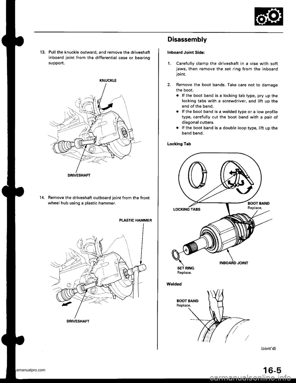
13, Pull the knuckle outward, and remove the driveshaft
inboard joint from the differential case or bearing
suoDort.
KNUCKLE
Remove the driveshaft outboard joint from the front
wheel hub using a plastic hammer.
PLASTIC HAMMER
14.
DRIVESHAFT
DRIVESHAFT
Disassembly
Inboard Joint Sid€:
1, Carefully clamp the driveshaft in a vise with softjaws, then remove the set ring from the inboardjoint.
2. Remove the boot bands. Take care not to damage
the boot,
. lf the boot band is a locking tab type, pry up the
locking tabs with a screwdriver, and lift up the
end of the band.
. lf the boot band isawelded typeora low profile
type, carefully cut the boot band with a pair of
diagonal cutters.
. lf the boot band is a double loop type. lift up the
band bend.
Locking Tab
SET BINGReplace.
Welded
{cont'd)
16-5
www.emanualpro.com
Page 837 of 1395
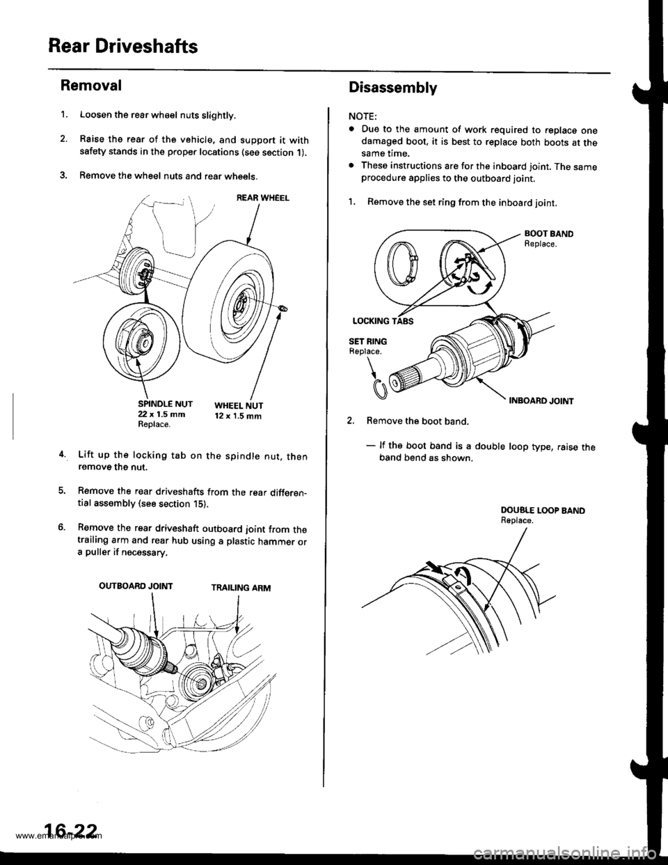
Rear Driveshafts
't.
Removal
Loosen the rear wh€el nuts slightly.
Raise the rear of the vehicle, and support it withsafety stands in the proper locations (see section 1),
Remove the wheel nuts and rear wheets.
SPINDLE NUT22 x 1.5 mmReplace.
WHEEL NUT12 x 1.5 mm
4.Lift up the locking tab on the spindle nut. thenremove the nut.
Remove the rear driveshafts from the rear differen-tial assembly (see section 15),
Remove the rear driveshaft outboard joint from thetrailing arm and rear hub using a plastic hammer ora puller if necessary.
TRAILING ARMOUTBOARD JOINT
16-22
Disassembly
NOTE:
a Due to the amount of work required to replace onedamaged boot, it is best to replace both boots at thesame time.
. These instructions are for the inboard joint. The sameprocedure applies to the outboard joint.
1, Remove the set ring from the inboard joint,
BOOT BANDReplace.
INBOARD JOINT
2. Remove the boot band.
- lf the boot band is a double loop type, raise theband bend as shown,
DOUSLE LOOP BANDReplace.
www.emanualpro.com
Page 846 of 1395

Steering
Special Toofs ............. 17-2
Component Locations
Index ................ ....... 17-3
Troubleshooting
General Troubleshooting ................ 1 7-4
Noise and Vibration ......................... 17-8
Fluid Leaks ............. 17-10
Inspection and Adiustment
Steering Operation .......................... 17-12
Power Assist Check
With Vehicle Parked ....................
Steering Linkage and Gearbox .......
Pump Belt
Rack Guide Adjustment ...................
Fluid Rep|acement ...................,,.,....
Pump Pressure Check .................,,...
*Steering Wheel
Removal ................. 17-18
*Steering Column
Removal/lnstallation ................ ....... 17 -2O
lnspection .............. 17-21
Steering Lock Replacement ............ 17 -22
Power Steering Hoses, Lines
Ffuid Leakage Inspection ................. 17 -23
Repfacement .......... 17-23
Power Steering Pump
Repfacement .......... 17-24
Disassembly ...........17-25
fnspection .............. 17-26
Reassembly ............ 17-28
Power Steering Gearbox
Removal ................. 17-31
Disassembly ........... 17-34
Reassembly ............ 17-40
Ball Joint Boot Replacement .......... 17-50
Installation ............. 17-51
17-12
17-13
17-14
l7-15
17-15
17-16
Disassembly/Reassembly............... 17-18
4'%/b.......... -r'-7--a/
SUPPLEN\EN AL RES\RA(N SYSTES{ (SRS\
This model has an SRS which includes a driver's airbag in the steering wheel hub. a passenger's airbag in the dashboardabove the glove box ('97 - 00 models), and seat belt tensioners in the seat belt retractors ('98 - 00 models). Informationnecessary to safely service the SRS is included in this Service Manual. ltems marked with an asterisk (*) on the contentspage include, or are located near, SBS components. Servicing. disassembling or replacing these items will require specialprecautions and tools, and should only be done by an authorized Honda oearer.
To avoid rendering the SRS inoperative, which could lead to peFonal iniury or death in the event of a sevore trontalcollision. allSRS service work must be performod by an authorized Honda dealer.lmproper service procedurgs, including incorrect removal and installalion of the SRS, could lead to personal iniurycaused by unintontional deployment of th€ airbags {'97 - 00 models), and seat belt tensioners ('98 - 00 modelsl.Do not bump the SRS unit. Otherwise, the system may lail in case ot a collision, or the airbags may deploy when theignition switch is ON (lll.
SRS electrical wiring harnesses are identitied by yellow colof coding. Ralated components are located in the steeringcolumn, front console, dashboard, dashboard lower panel, and in the dashboard above the glove box. Do not use elec-trical test equipment on these cilcuits,
www.emanualpro.com
Page 863 of 1395
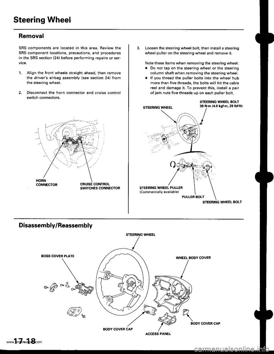
Steering Wheel
Removal
SRS components are located in this area. Review the
SRS component locations, precautions, and procedures
in the SRS section (24) before performing repairs or ser-
vice.
1. Align the front wheels straight ahead. then remove
the driver's airbag assembly (see section 24) from
the steering wheel.
2. Disconnect the horn connector and cruise control
switch connectors.
CONTROLSWITCHES CONNECTOR
3. Loosen the steering wheel bolt, then install a steering
wheel puller on the steering wheel and remove it.
Note these items when removing the steering wheel:
. Do not tap on the steering wheel or the steering
column shaft when removing the steering wheel.
. lf you thread the puller bolts into the wheel hub
more than five threads, the bolts will hit the cable
reel and damage it. To prevent this, install a pair
of jam nuts five threads up on each puller bolt.
STEERING WHEEL BOLT39 N.m 14.0 kgt.m,29 lbtftl
STEERING WHEEL EOLT
Disassembly/Reassembly
EOSS COVER PLATE
_^M
STEERING WHEEL
WHEEL BODY COVER
17-18
@,
ACCESS PANEL
h"\
BODYCOVER CAP
www.emanualpro.com
Page 899 of 1395
Suspension
Special Tools ............. 18-2
Component Locations
lndex ................ ...... 18-3
Wheel Alignment
Service lnformation ......................,.. 18-4
Camber .................. 18-4
Caster ............... ...... 18-5
Front Toe Inspection/
Adiustment ........ 18-5
Rear Toe Inspection/
Adiustment ........ 18-6
Turning Angle Inspection/
Adiustment ........ 18-6
Wheel/Hub Inspection
Bearing End Play .......................,...... 18-7
Wheel Runout ....... 18-7
Front Suspension
Suspension Arms Replacement ..... 18-8
Knuckle/Hub Replacement ............. 18-9
Lower Ball Joint Replacement ....... 18-15
Ball Joint Boot Replacement .......... 18-16
Front Damper
Removal ................. 18-16
Disassembly/lnspection .................. 18-1 7
Reassembly ........... 18-18
lnstallation ............. 18-18
Rear Suspension
Suspension Arms Replacement ..... 18-19
Hub Bearing Unit Replacement ...... 18-20
Upper Arm Bushing
Replacement ..... 18-23
Rear Damper
Removal ................. 18-23
Disassembly/1nspection .................. 18-24
Reassembly ........... 18-25
lnstallation ............. 18-25
www.emanualpro.com
Page 905 of 1395
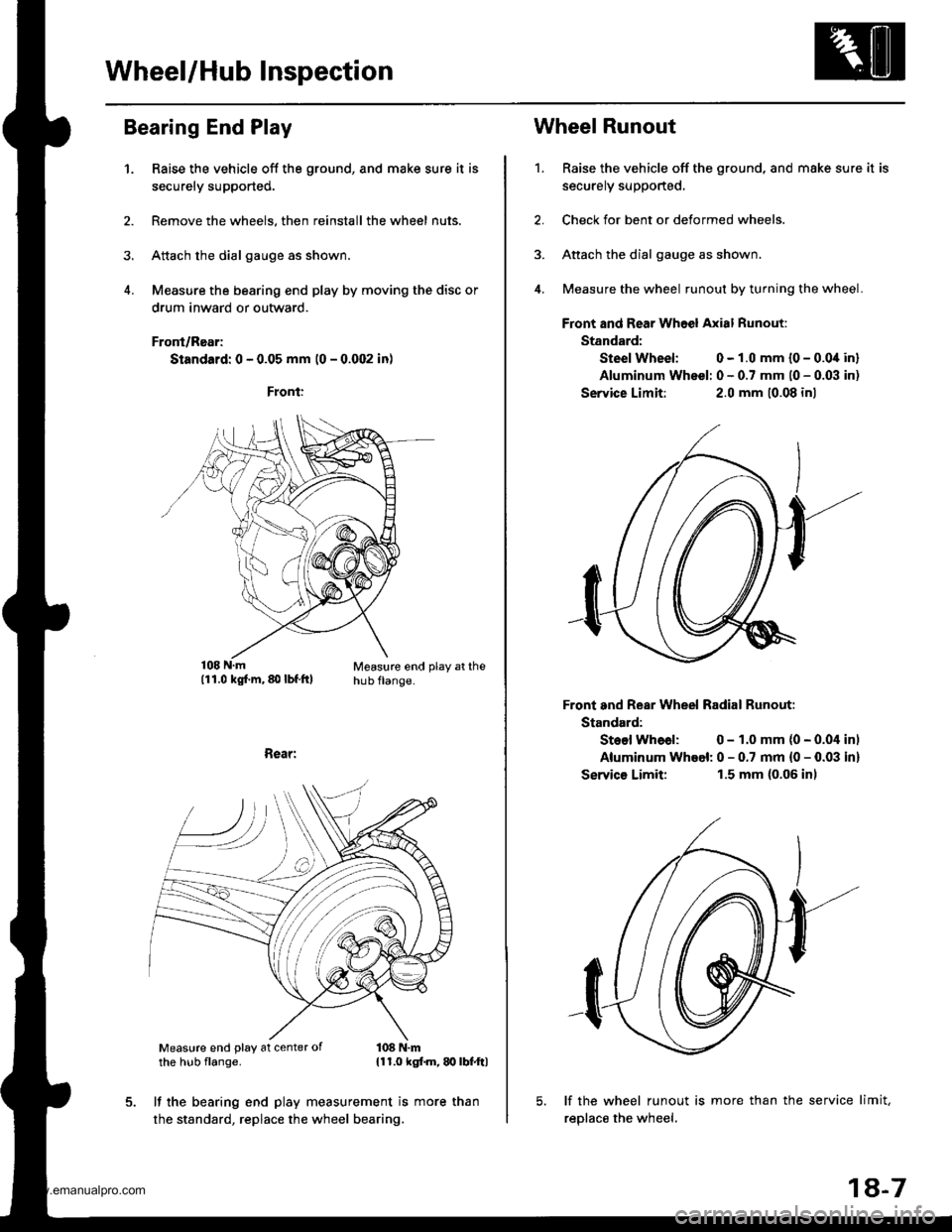
Wheel/Hub lnspection
Bearing End Play
1.Raise the vehicle off the ground, and make sure it is
securely supported.
Remove the wheels, then reinstall the wheel nuts.
Attach the dial gauge as shown.
Measure the bearing end play by moving the disc or
drum inward or outward.
Front/Rear;
Standard: 0 - 0.05 mm (0 - 0.002 in)
Measure end play at thehub flange.
Rear:
Measure end play at center ofthe hub flange.108 N.m{11.0 kgf.m, q} lbf.ftl
It the bearing end play measurement is more than
the standard, replace the wheel bearing.
1.
Wheel Runout
Raise the vehicle off the ground, and make sure it is
securely supported,
Check for bent or deformed wheels.
Attach the dial gauge as shown.
Measure the wheel runout by turning the wheel.
Front and Rear Whoel Axial Runout:
Standard:
Steel Wheel: 0 - 1.0 mm {0 - 0.0i[ in]
Aluminum Wheel: 0 - 0.7 mm l0 - 0.03 in)
Service Limit:2.0 mm 10.08 inl
Front and Rear Wheel Radial Runout:
Standard:
Steel Whoal: 0 - 1.0 mm (0 - 0.04 inl
Aluminum Whoel: 0 - 0.7 mm {0 - 0.03 in}
Servics Limit:1.5 mm (0.06 inl
lf the wheel runout is more than the service limit,
reolace the wheel.
18-7
www.emanualpro.com
Page 907 of 1395
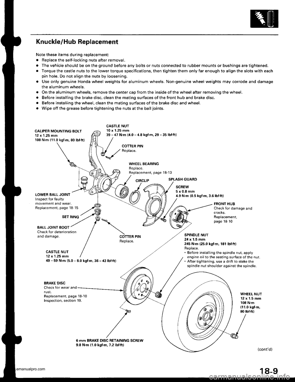
Knuckle/Hub Replacement
Note these items during replacement:
. Replace the selt-locking nuts after removal.
. The vehicle should be on the ground before any bolts or nuts connected to rubber mounts or bushings are tightened.
. Torque the castle nuts to the lower torque specifications, then tighten them only far enough to align the slots with each
pin hole. Do not align the nuts by loosening.
o Use only genuine Honda wheel weights for aluminum wheels. Non'genuine wheel weights may corrode and damage
the aluminum wheels.
. Onthealuminum wheels, remove the center cap from the inside of the wheel after removing the wheel.
. Before installing the brake disc, clean the mating surfaces of the front hub and brake disc.
. Before installing the wheel. clean the mating surfaces ofthe brake disc and wheel.
. Wipe off the grease before tightening the nuts at the balljoints.
CALIPER MOUNTING BOLT12 x 1.25 mm108 N.m (11.0 kgtm.80 lbt.ftl
LOWER BALL JOINTInspect for faultymovement and wear,Replacement, page'18 15
CASTLE NUT10 x 1.25 mm39 - 47 N.m (i1.0 - 4.8 kgf.m, 29 - 35 lbf.ftl
COTTER PINReplace.
WHEEL BEARINGBeplace.Replacement, page 18-13
CIRCLIPSPLASH GUARD
SCREW5x0.8mm4.9 N.m {0.5 kgf.m,3.6lbf.ft)
SET RING
FRONT HUBCheck for damage and
Replacement,page 18 10
BALL JOINT BOOTCheck for deteriorationano oamage.SPINOLE NUT24 x 1.5 mm245 N.m {25.0 kgI.m, 181 lbtft}Replace.. Before installing the spindle nut, applyengine oil to the seating surface of the nut.. After tightening, use a drift to stake thespindle nut shoulder against the spindle.
COTTER PINReplace.
CASTLE NUT12x 1.25 fim49 - 59 N.m 15.0 - 6.0 kgt.m. 36 - € lbf.ft)
BRAKE DISCCheck for wear andrust.Replacement, page 18-10Inspection, section 19.
WHEEL NUT12 x 1.5 mm108 N.m{11.0 kgt m,80 tbf.ftl
6 mm BRAKE DISC RETAINING SCREW9.8 N.m (1.0 kgtm, 7.2 lbtftl(cont'd )
18-9
www.emanualpro.com