horn HONDA CR-V 2015 RM1, RM3, RM4 / 4.G Quick Guide
[x] Cancel search | Manufacturer: HONDA, Model Year: 2015, Model line: CR-V, Model: HONDA CR-V 2015 RM1, RM3, RM4 / 4.GPages: 81, PDF Size: 14.87 MB
Page 4 of 81

| 1
VISUAL INDEX
Quickly locate items in the vehicle’s interior.
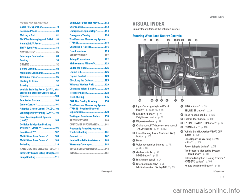
Steering Wheel and Nearby Controls
1 Lights/turn signals/LaneWatch
button* p. 39, p. 40, p. 107
2 SEL/RESET knob* p. 28
Brightness control p. 39
3 Wipers/washers p. 41
4 Cruise control*/Adaptive cruise control
(ACC)* buttons p. 101, p. 102
5 Lane Keeping Assist System (LKAS)
button p. 105
6 Horn
7 Voice recognition buttons p. 74,
p. 78, p. 86
8 Audio controls p. 55
i-MID button* p. 57
9 Instrument panel p. 24
10 Information display* p. 28
Multi-Information Display (MID)* p. 29
11 INFO buttons* p. 29
SEL/RESET button* p. 29
12 Hood release handle p. 125
13 Fuel fi ll door handle p. 110
14 ENGINE START/STOP button* p. 97
15 ECON button* p. 100
16 Vehicle Stability Assist (VSA®) OFF
button p. 100
Lane Departure Warning (LDW)
button* p. 104
Power tailgate button* p. 36
Tire Pressure Monitoring System
(TPMS) button* p. 115
Collision Mitigation Braking System™
(CMBS™) button* p. 106
Heated windshield button* p. 51
VISUAL INDEX
*if equipped
*if equipped
92
567111213
1815341014
16
Models with touchscreen
Basic HFL Operation ....................... 78
Pairing a Phone ............................... 80
Making a Call .................................. 81
SMS Text Messaging and E-Mail* ... 83
HondaLink™ Assist ........................ 84
Siri™ Eyes Free ............................... 84
NAVIGATION* .................................. 85
Entering a Destination ................... 88
Routing .............................................. 90
DRIVING ............................................ 92
Before Driving ................................. 92
Maximum Load Limit ...................... 94
Towing a Trailer .............................. 96
Starting to Drive .............................. 97
Braking ............................................. 99
Vehicle Stability Assist (VSA
®), aka
Electronic Stability Control (ESC)
System ............................................. 100
Eco Assist System ......................... 100
Cruise Control* .............................. 101
Adaptive Cruise Control (ACC)* ... 102
Lane Departure Warning (LDW)* ... 104
Lane Keeping Assist System
(LKAS)* ............................................ 105
Collision Mitigation Braking
System™ (CMBS™)* .................... 106
LaneWatch™* ............................... 107
Multi-View Rear Camera* ........... 108
Multi-View Rear Camera* ........... 109
Refueling ........................................ 110
HANDLING THE UNEXPECTED ... 111
Smart Entry Remote Battery Strength ....111
Jump Starting ................................ 111 Shift Lever Does Not Move ......... 112
Overheating .................................... 113
Emergency Engine Stop* ............. 114
Emergency Towing ....................... 114
Tire Pressure Monitoring System
(TPMS) ............................................ 115
Changing a Flat Tire ...................... 116
Fuse Locations ............................... 119
MAINTENANCE ............................. 122
Safety Precautions ....................... 122
Maintenance Minder™................ 123
Under the Hood .............................. 125
Engine Oil ....................................... 126
Engine Coolant .............................. 128
Checking the Battery .................... 129
Window Washer Fluid ................. 129
Changing Wiper Blades ............... 130
Tire Information ............................. 132
Tire Labeling .................................. 135
DOT Tire Quality Grading ............. 136
Tire Pressure Monitoring System
(TPMS) - Required Federal
Explanation .................................... 138
Testing of Readiness Codes ........ 139
SPECIFICATIONS ........................... 140
CUSTOMER INFORMATION ......... 141
Frequently Asked Questions/
Troubleshooting ............................ 141
Contact Us ...................................... 142
Honda Roadside Assistance ....... 143
Warranty Coverages ..................... 143
VOICE COMMAND INDEX ............ 144
INDEX .............................................. 151
Page 63 of 81

118 || 119
HANDLING THE UNEXPECTED
HANDLING THE UNEXPECTED
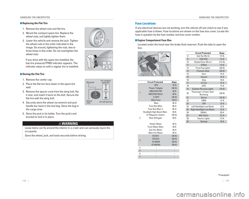
Replacing the Flat Tire
1. Remove the wheel nuts and fl at tire.
2. Mount the compact spare tire. Replace the wheel nuts, and lightly tighten them.
3. Lower the vehicle and remove the jack. Tighten the wheel nuts in the order indicated in the
image. Go around, tightening the nuts, two to
three times in this order. Do not overtighten the
wheel nuts.
If you drive with the spare tire installed, the
low tire pressure/TPMS indicator appears. The
indicator stays on until a regular tire is installed.
Storing the Flat Tire 1. Remove the center cap.
2. Place the fl at tire face down in the spare tire well.
3. Remove the spacer cone from the wing bolt, fl ip it over, and insert it back on the bolt. Secure the
fl at tire with the wing bolt.
4. Securely store the wheel nut wrench and jack handle bar back in the tool bag. Store the bag in
the cargo area.
5. Store the jack in its holder. Turn the jack’s end bracket to lock it in place.
Wing bolt
Spacer
cone For compact
spare tire
For full-size tire
Loose items can fl y around the interior in a crash and can seriously injure the
occupants.
Store the wheel, jack, and tools securely before driving.
WARNING
Fuse Locations
If any electrical devices are not working, turn the vehicle off and chec\
k to see if any
applicable fuse is blown. Fuse locations are shown on the fuse box cover\
. Locate the
fuse in question by the fuse number and box cover number.
Engine Compartment Fuse Box Located under the hood near the brake fl uid reservoir. Push the tabs to open the
box.
89VSA ECU7.5 A
10 (7.5 A)
11STRLD7.5 A
12 (20 A)
13Premium Amp*(20 A)
14
15Hazard10 A
16
17IG Coil15 A
18
19Daytime Running Lights(10 A)
20 Passenger’s Power Seat
Reclining (20 A)
21Deicer(15 A)
22
23IGP15 A
24
25Right Headlight Low Beam10 A
26
27MG Clutch7.5 A
28
29Backup10 A
Circuit ProtectedAmps7.5 A
10 A10 A
15 A
15 A
10 A
20 A
7.5 A
Sub Fan Rly CL
HornStop
IGP2
DBW
Left Headlight Low Beam SMALL
Interior Lights
Heated Door Mirror
*
Front Fog Lights*
Circuit ProtectedAmps
1
EPS70 APower Tailgate(40 A)ABS/VSA FSR20 AABS/VSA Motor40 AE-DPS*(30 A)Main Fuse120 A
2
Main50 A
Fuse Box Main
Fuse Box Main 260 A
Headlight High Beam Main
ST Magnetic Switch(30 A)
Rear Defogger −
Heater Motor
Front Wiper Main Sub Fan Motor
Main Fan Motor
3
DC/DC1(30 A)DC/DC2(30 A)IG MAIN(30 A)IG MAIN2(30 A)
4
5−−
6
7−−
60 A
30 A
30 A −
40 A
30 A 20 A
20 A
−
−
−
−
*if equipped
Ta
b