eps HONDA CR-V 2016 RM1, RM3, RM4 / 4.G Owners Manual
[x] Cancel search | Manufacturer: HONDA, Model Year: 2016, Model line: CR-V, Model: HONDA CR-V 2016 RM1, RM3, RM4 / 4.GPages: 532, PDF Size: 22.94 MB
Page 12 of 532
11
Quick Reference Guide
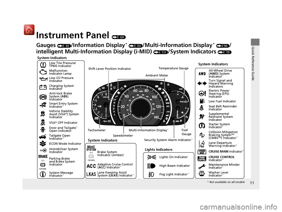
Instrument Panel (P 69)
System Indicators
Malfunction
Indicator Lamp
Low Oil Pressure
Indicator
Charging System
Indicator
Anti-lock Brake
System (ABS)
Indicator
Vehicle Stability
Assist (VSA ®) System
Indicator
VSA ® OFF Indicator
Low Tire Pressure/
TPMS Indicator
Lights Indicators
Lights On Indicator
High Beam Indicator
Fog Light Indicator
*
Immobilizer System
Indicator
Seat Belt Reminder
Indicator
System Indicators
CRUISE CONTROL
Indicator*Parking Brake
and Brake System
Indicator Supplemental
Restraint System
Indicator
Door and Tailgate
*
Open Indicator
CRUISE MAIN Indicator
*
Tachometer
Speedometer Fuel
Gauge
Security System Alarm Indicator
*
Shift Lever Position Indicator
Low Fuel Indicator
Gauges (P 92)/Information Display* (P 93)/Multi-Information Display* (P96)/
intelligent Multi-Inform ation Display (i-MID)
(P 111)/System Indicators (P 70)
Tailgate Open
Indicator
*
ECON Mode Indicator Maintenance Minder
Indicator
*
Washer Level
Indicator*
Ambient MeterTemperature Gauge
Electric Power
Steering (EPS)
Indicator Turn Signal and
Hazard Warning
Indicators
All-Wheel Drive
(
AWD ) System
Indicator
*
System Indicators
Canada U.S.
Smart Entry System
Indicator*
Lane Keeping Assist
System (
LKAS) Indicator*
Adaptive Cruise Control
(ACC ) Indicator*
Starter System
Indicator*
Collision Mitigation
Braking SystemTM
(CMBSTM) Indicator*
Lane Departure
Warning Indicator*
System Message
Indicator*
Multi-Information Display*
Canada U.S.
Brake System
Indicator (Amber)
*
Not available on all models
15 CR-V-31T0A6300.book 11 ページ 2015年2月2日 月曜日 午前10時35分
Page 63 of 532
uuChild Safety uSafety of Infants and Small Children
62
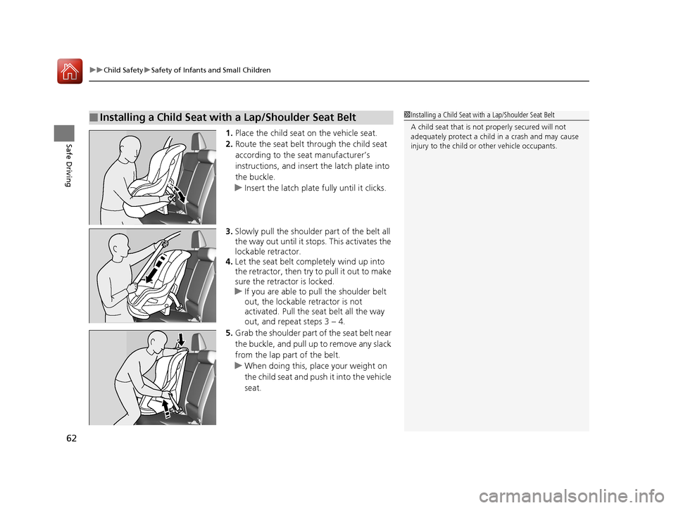
Safe Driving1. Place the child seat on the vehicle seat.
2. Route the seat belt through the child seat
according to the seat manufacturer’s
instructions, and insert the latch plate into
the buckle.
u Insert the latch plate fully until it clicks.
3. Slowly pull the shoulder part of the belt all
the way out until it stops. This activates the
lockable retractor.
4. Let the seat belt completely wind up into
the retractor, then try to pull it out to make
sure the retractor is locked.
u If you are able to pull the shoulder belt
out, the lockable retractor is not
activated. Pull the seat belt all the way
out, and repeat steps 3 – 4.
5. Grab the shoulder part of the seat belt near
the buckle, and pull up to remove any slack
from the lap part of the belt.
u When doing this, place your weight on
the child seat and push it into the vehicle
seat.
■Installing a Child Seat with a Lap/Shoulder Seat Belt1Installing a Child Seat with a Lap/Shoulder Seat Belt
A child seat that is not properly secured will not
adequately protect a child in a crash and may cause
injury to the child or other vehicle occupants.
15 CR-V-31T0A6300.book 62 ページ 2015年2月2日 月曜日 午前10時35分
Page 77 of 532
76
uuIndicators u
Instrument Panel
*1:Models with the smart entry system have an ENGINE START/STOP button instead of an ignition switch.
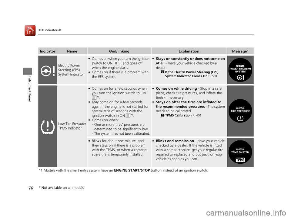
IndicatorNameOn/BlinkingExplanationMessage*
Electric Power
Steering (EPS)
System Indicator
●Comes on when you turn the ignition
switch to ON
(w*1, and goes off
when the engine starts.
●Comes on if there is a problem with
the EPS system.
●Stays on constantly or does not come on
at all - Have your vehicle checked by a
dealer.
2 If the Electric Power Steering (EPS)
System Indicator Comes On P. 501
Low Tire Pressure/
TPMS Indicator
●Comes on for a few seconds when
you turn the ignition switch to ON
(w*1.●May come on for a few seconds
again if the engine is not started for
several tens of seconds with the
ignition switch in ON
(w*1.●Comes on when:
-One or more tires’ pressures are
determined to be significantly low.
- The system has not been calibrated.
●Comes on while driving - Stop in a safe
place, check tire pres sures, and inflate the
tire(s) if necessary.
●Stays on after the tires are inflated to
the recommended pressures - The system
needs to be calibrated.
2 TPMS Calibration P. 401
●Blinks for about one minute, and
then stays on if there is a problem
with the TPMS, or when a compact
spare tire is temporarily installed.●Blinks and remains on - Have your vehicle
checked by a dealer. If the vehicle is fitted
with a compact spare, get your regular tire
repaired or replaced and put back on your
vehicle as soon as you can.
* Not available on all models
15 CR-V-31T0A6300.book 76 ページ 2015年2月2日 月曜日 午前10時35分
Page 110 of 532
109
uuGauges and Displays uMulti-Information Display*
Continued
Instrument Panel
■Example of customization settings
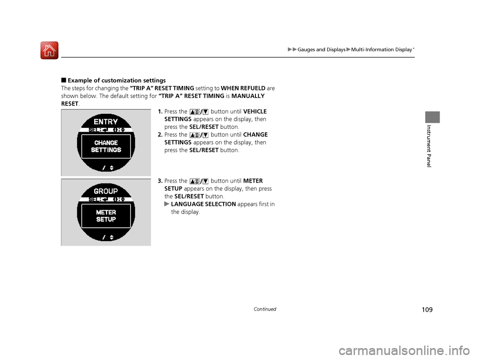
The steps for changing the “TRIP A” RESET TIMING setting to WHEN REFUELD are
shown below. The default setting for “TRIP A” RESET TIMING is MANUALLY
RESET .
1.Press the button until VEHICLE
SETTINGS appears on the display, then
press the SEL/RESET button.
2. Press the button until CHANGE
SETTINGS appears on the display, then
press the SEL/RESET button.
3. Press the button until METER
SETUP appears on the display, then press
the SEL/RESET button.
u LANGUAGE SELECTION appears first in
the display.
15 CR-V-31T0A6300.book 109 ページ 2015年2月2日 月曜日 午前10時35分
Page 130 of 532
129
uuClock uAdjusting the Clock
Controls
■Using the SETUP button
1. Press the SETUP button.
2. Rotate to select Adjust Clock, then press .
3. Rotate to select the item you want to change (12/24 hour mode, hour,
minute). Then press .
4. Rotate to make the adjustment.
5. Press to enter your selection. The display returns to Adjust Clock. Repeat steps
4 to 6 to adjust other items.
6. To enter the selection, Rotate and select Set, then press .
7. Press the SETUP button to go back to the normal display.
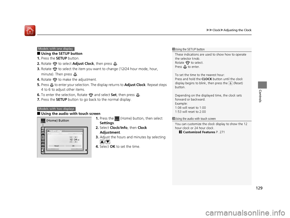
■Using the audio wi th touch screen
1.Press the (Home) button, then select
Settings .
2. Select Clock/Info , then Clock
Adjustment .
3. Adjust the hours and minutes by selecting
/.
4. Select OK to set the time.
1Using the SETUP button
These indications are used to show how to operate
the selector knob.
Rotate to select.
Press to enter.
To set the time to the nearest hour:
Press and hold the CLOCK button until the clock
display begins to blink, then press the
( 6 (Reset)
button.
Depending on the displayed time, the clock sets
forward or backward.
Example:
1:06 will reset to 1:00
1:53 will reset to 2:00
Models with one display
Models with two displays
(Home) Button
34
1 Using the audio with touch screen
You can customize the clock display to show the 12
hour clock or 24 hour clock.
2 Customized Features P. 271
15 CR-V-31T0A6300.book 129 ページ 2015年2月2日 月曜日 午前10時35分
Page 142 of 532
Continued141
uuOpening and Closing the Tailgate uPrecautions for Opening/Closing the Tailgate
Controls
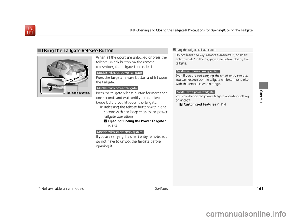
When all the doors are unlocked or press the
tailgate unlock button on the remote
transmitter, the tailgate is unlocked.
Press the tailgate release button and lift open
the tailgate.
Press the tailgate release button for more than
one second, and wait until you hear two
beeps before you lift open the tailgate. u Releasing the releas e button within one
second with one beep enables the power
tailgate operations.
2 Opening/Closing the Power Tailgate*
P. 143
If you are carrying the smart entry remote, you
do not have to unlock the tailgate before
opening it.
■Using the Tailgate Release Button1 Using the Tailgate Release Button
Do not leave the key, remote transmitter
*, or smart
entry remote* in the luggage area before closing the
tailgate.
Even if you are not carrying the smart entry remote,
you can lock/unlock the tail gate while someone else
with the remote is within range.
You can change the power tailgate operation setting
on and off. 2 Customized Features P. 114
Models with smart entry system
Models with power tailgateRelease Button
Models without power tailgate
Models with power tailgate
Models with smart entry system
* Not available on all models
15 CR-V-31T0A6300.book 141 ページ 2015年2月2日 月曜日 午前10時35分
Page 165 of 532
164
uuOperating the Switches Around the Steering Wheel uWipers and Washers
Controls
Wipers and Washers
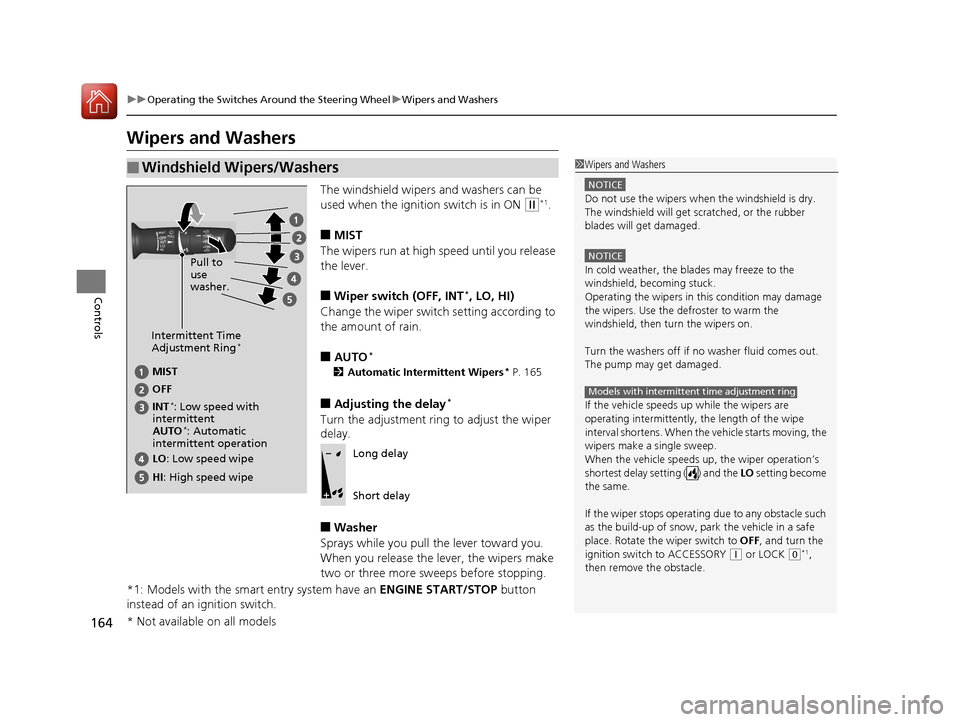
The windshield wipers and washers can be
used when the ignition switch is in ON
(w*1.
■MIST
The wipers run at high speed until you release
the lever.
■Wiper switch (OFF, INT*, LO, HI)
Change the wiper switch setting according to
the amount of rain.
■AUTO*
2 Automatic Intermittent Wipers* P. 165
■Adjusting the delay*
Turn the adjustment ring to adjust the wiper
delay.
■Washer
Sprays while you pull the lever toward you.
When you release the lever, the wipers make
two or three more sweeps before stopping.
*1: Models with the smart entry system have an ENGINE START/STOP button
instead of an ignition switch.
■Windshield Wipers/Washers1 Wipers and Washers
NOTICE
Do not use the wipers when the windshield is dry.
The windshield will get sc ratched, or the rubber
blades will get damaged.
NOTICE
In cold weather, the blades may freeze to the
windshield, becoming stuck.
Operating the wipers in th is condition may damage
the wipers. Use the defroster to warm the
windshield, then turn the wipers on.
Turn the washers off if no washer fluid comes out.
The pump may get damaged.
If the vehicle speeds up while the wipers are
operating intermittently, the length of the wipe
interval shortens. When the vehicle starts moving, the
wipers make a single sweep.
When the vehicle speeds up, the wiper operation’s
shortest delay setting ( ) and the LO setting become
the same.
If the wiper stops operating due to any obstacle such
as the build-up of snow, pa rk the vehicle in a safe
place. Rotate the wiper switch to OFF, and turn the
ignition switch to ACCESSORY
( q or LOCK ( 0*1,
then remove the obstacle.
Models with intermittent time adjustment ring
Intermittent Time
Adjustment Ring*
MIST
INT
*: Low speed with
intermittent OFF
LO : Low speed wipe
HI: High speed wipe Pull to
use
washer.
AUTO*: Automatic
intermittent operation
Long delay
Short delay
* Not available on all models
15 CR-V-31T0A6300.book 164 ページ 2015年2月2日 月曜日 午前10時35分
Page 167 of 532
166
uuOperating the Switches Around the Steering Wheel uWipers and Washers
Controls
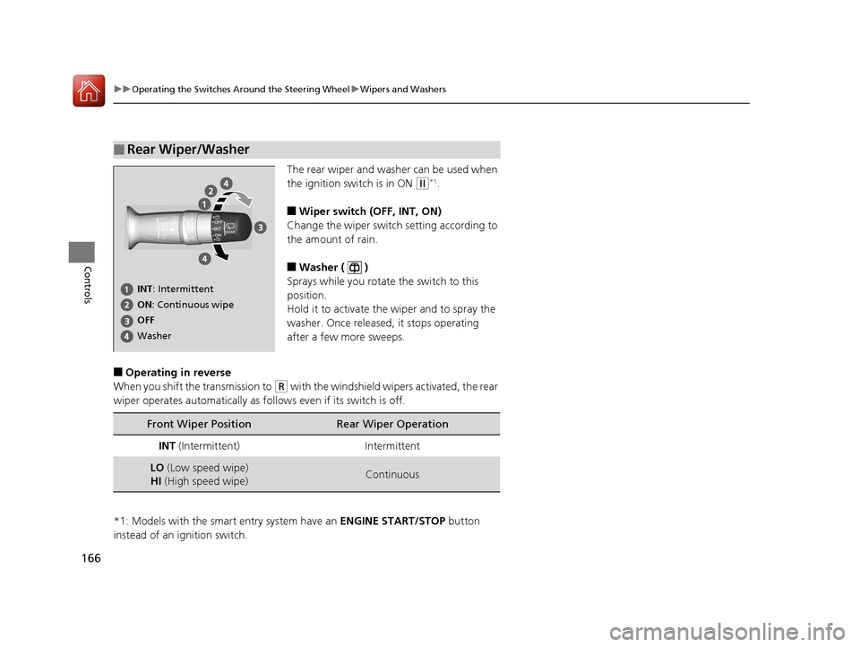
The rear wiper and washer can be used when
the ignition switch is in ON
(w*1.
■Wiper switch (OFF, INT, ON)
Change the wiper switch setting according to
the amount of rain.
■Washer ( )
Sprays while you rotate the switch to this
position.
Hold it to activate the wiper and to spray the
washer. Once released, it stops operating
after a few more sweeps.
■Operating in reverse
When you shift th e transmission to
(R with the windshield wipe rs activated, the rear
wiper operates automatically as fo llows even if its switch is off.
*1: Models with the smart entry system have an ENGINE START/STOP button
instead of an ignition switch.
■Rear Wiper/Washer
INT : Intermittent
OFF ON : Continuous wipe
Washer
Front Wiper PositionRear Wiper Operation
INT (Intermittent)Intermittent
LO (Low speed wipe)
HI (High speed wipe)Continuous
15 CR-V-31T0A6300.book 166 ページ 2015年2月2日 月曜日 午前10時35分
Page 284 of 532
283
uuHomeLink ® Universal Transceiver*u Training HomeLink
Features
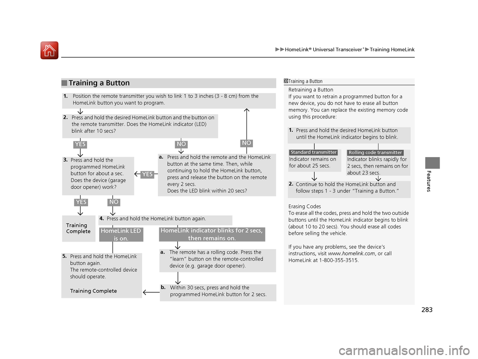
■Training a Button1Training a Button
Retraining a Button
If you want to retrain a programmed button for a
new device, you do not ha ve to erase all button
memory. You can replace the existing memory code
using this procedure:
Erasing Codes
To erase all the codes, press and hold the two outside
buttons until the HomeLink i ndicator begins to blink
(about 10 to 20 secs). You should erase all codes
before selling the vehicle.
If you have any problems, see the device’s
instructions, visit www.homelink.com , or call
HomeLink at 1-800-355-3515.
1. Press and hold the desired HomeLink button
until the HomeLink indi cator begins to blink.
2.
Continue to hold the HomeLink button and
follow steps 1 - 3 unde r “Training a Button.”
Indicator remains on
for about 25 secs.
Standard transmitter
Indicator blinks rapidly for
2 secs, then remains on for
about 23 secs.
Rolling code transmitter
4.
a.3.
2.
5.a.
b.
1.
Position the remote transmitter you wish to link 1 to 3 inches (3 - 8 cm) from the
HomeLink button you want to program.
Press and hold the desired HomeLink button and the button on
the remote transmitter. Does the HomeLink indicator (LED)
blink after 10 secs?
Press and hold the
programmed HomeLink
button for about a sec.
Does the device (garage
door opener) work? Press and hold the remote and the HomeLink
button at the same time. Then, while
continuing to hold the HomeLink button,
press and release the button on the remote
every 2 secs.
Does the LED blink within 20 secs?
Training
Complete Press and hold the HomeLink button again.
Press and hold the HomeLink
button again.
The remote-controlled device
should operate.
Training Complete The remote has a ro
lling code. Press the
“learn” button on the remote-controlled
device (e.g. garage door opener).
Within 30 secs, press and hold the
programmed HomeLink button for 2 secs.
HomeLink indicator blinks for 2 secs, then remains on.HomeLink LED is on.
YESNO
YES
YESNONO
15 CR-V-31T0A6300.book 283 ページ 2015年2月2日 月曜日 午前10時35分
Page 352 of 532
351
uuBefore Driving uMaximum Load Limit
Continued
Driving
Maximum Load Limit
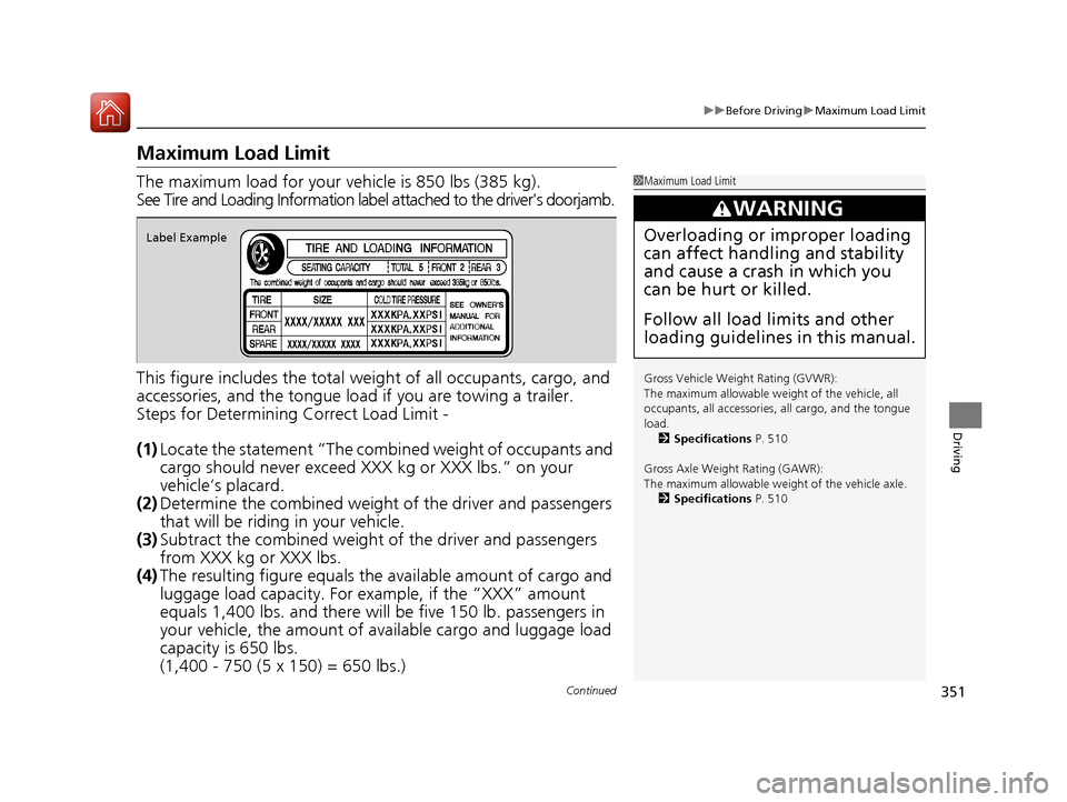
The maximum load for your ve hicle is 850 lbs (385 kg).
See Tire and Loading Information label attached to the driver's doorjamb.
This figure includes the total weig ht of all occupants, cargo, and
accessories, and the tongue load if you are towing a trailer.
Steps for Determining Correct Load Limit -
(1) Locate the statement “The comb ined weight of occupants and
cargo should never exceed XXX kg or XXX lbs.” on your
vehicle’s placard.
(2) Determine the combined weight of the driver and passengers
that will be riding in your vehicle.
(3) Subtract the combined weight of the driver and passengers
from XXX kg or XXX lbs.
(4) The resulting figure equals the available amount of cargo and
luggage load capacity. For example, if the “XXX” amount
equals 1,400 lbs. and there will be five 150 lb. passengers in
your vehicle, the am ount of available cargo and luggage load
capacity is 650 lbs.
(1,400 - 750 (5 x 150) = 650 lbs.)1 Maximum Load Limit
Gross Vehicle Weight Rating (GVWR):
The maximum allowable weight of the vehicle, all
occupants, all a ccessories, all cargo, and the tongue
load. 2 Specifications P. 510
Gross Axle Weight Rating (GAWR):
The maximum allowable weight of the vehicle axle. 2 Specifications P. 510
3WARNING
Overloading or improper loading
can affect handling and stability
and cause a crash in which you
can be hurt or killed.
Follow all load limits and other
loading guidelines in this manual.Label Example
15 CR-V-31T0A6300.book 351 ページ 2015年2月2日 月曜日 午前10時35分