headlights HONDA ELEMENT 2010 1.G User Guide
[x] Cancel search | Manufacturer: HONDA, Model Year: 2010, Model line: ELEMENT, Model: HONDA ELEMENT 2010 1.GPages: 342, PDF Size: 5.76 MB
Page 109 of 342

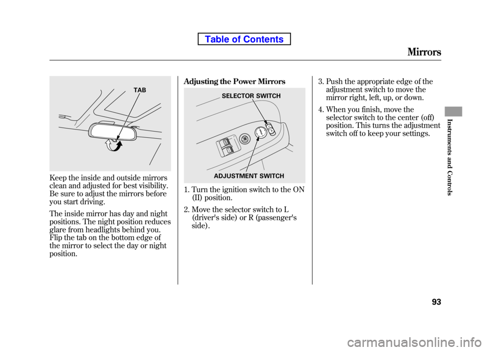
Keep the inside and outside mirrors
clean and adjusted for best visibility.
Be sure to adjust the mirrors before
you start driving.
The inside mirror has day and night
positions. The night position reduces
glare from headlights behind you.
Flip the tab on the bottom edge of
the mirror to select the day or nightposition.Adjusting the Power Mirrors
1. Turn the ignition switch to the ON
(II) position.
2. Move the selector switch to L (driver's side) or R (passenger's side). 3. Push the appropriate edge of the
adjustment switch to move the
mirror right, left, up, or down.
4. When you finish, move the selector switch to the center (off)
position. This turns the adjustment
switch off to keep your settings.
TABSELECTOR SWITCH
ADJUSTMENT SWITCH
Mirrors
93
Instruments and Controls
Table of Contents
Page 264 of 342

However, service at a dealer is not
mandatory to keep your warranties in
effect. Maintenance may be done by
any qualified service facility or
person who is skilled in this type of
automotive service. Make sure to
have the service facility or person
reset the display as previously
described. Keep all receipts as proof
of completion, and have the person
who does the work fill out your
Honda Service History or Canadian
Maintenance Log. Check your
warranty booklet for moreinformation.
We recommend using Honda parts
and fluids whenever you have
maintenance done. These are
manufactured to the same high
quality standards as the original
components, so you can be confident
of their performance and durability.U.S. Vehicles:
According to state and federal
regulations, failure to perform
maintenance on the items marked with
#will not void your emissions
warranties. However, all
maintenance services should be
performed in accordance with the
intervals indicated by the informationdisplay.
Owner's Maintenance Checks
You should check the following
items at the specified intervals. If you
are unsure of how to perform any
check, turn to the appropriate pagelisted.
● Engine oil level -Check every
time you fill the fuel tank. See page201.
● Engine coolant level -Check the
radiator reserve tank every time
you fill the fuel tank. See page 201. ●
Automatic transmission -Check
the fluid level monthly. See page256.
● Brakes -Check the fluid level
monthly. See page 258.
● Tires -Check the tire pressure
monthly. Examine the tread for
wear and foreign objects. See page271.
● Lights -Check the operation of
the headlights, parking lights,
taillights, high-mount brake light,
and license plate lights monthly.
See page 261.
Maintenance Minder
248
Table of Contents
Page 277 of 342

Headlight Aiming
The headlights were properly aimed
when your vehicle was new. If you
regularly carry heavy items in the
cargo area or pull a trailer,
readjustment may be required.
Adjustments should be done by your
dealer or another qualifiedtechnician.Replacing a Headlight Bulb
Your vehicle has halogen headlight
bulbs. Handle it by its steel base and
protect the glass from contact with
your skin or hard objects. If you
touch the glass, clean it with
denatured alcohol and a clean cloth.
Halogen headlight bulbs get very hot
when lit. Oil, perspiration, or a scratch
on the glass can cause the bulb to
overheat and shatter.
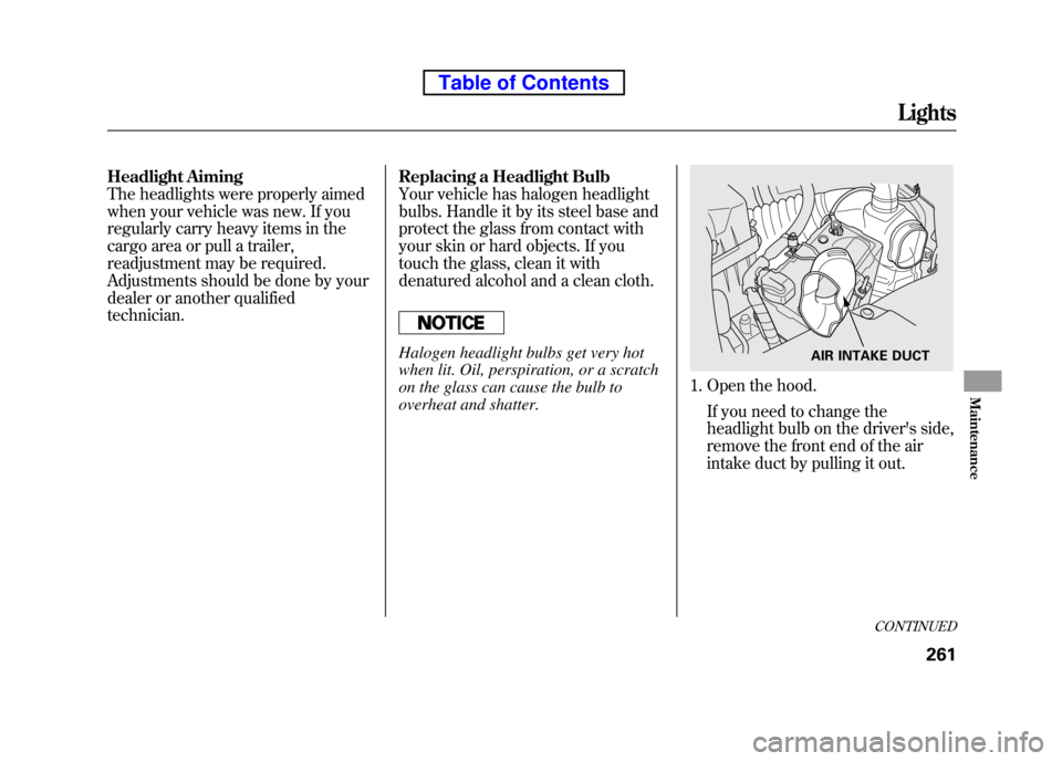
1. Open the hood.
If you need to change the
headlight bulb on the driver's side,
remove the front end of the air
intake duct by pulling it out.
AIR INTAKE DUCT
CONTINUED
Lights
261
Maintenance
Table of Contents
Page 278 of 342

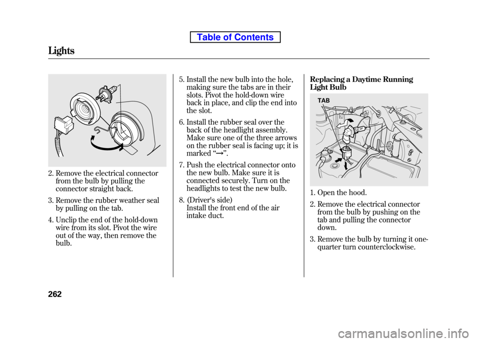
2. Remove the electrical connectorfrom the bulb by pulling the
connector straight back.
3. Remove the rubber weather seal by pulling on the tab.
4. Unclip the end of the hold-down wire from its slot. Pivot the wire
out of the way, then remove thebulb. 5. Install the new bulb into the hole,
making sure the tabs are in their
slots. Pivot the hold-down wire
back in place, and clip the end into
the slot.
6. Install the rubber seal over the back of the headlight assembly.
Make sure one of the three arrows
on the rubber seal is facing up; it ismarked ‘‘
’’.
7. Push the electrical connector onto the new bulb. Make sure it is
connected securely. Turn on the
headlights to test the new bulb.
8. (Driver's side) Install the front end of the air
intake duct. Replacing a Daytime Running
Light Bulb
1. Open the hood.
2. Remove the electrical connector
from the bulb by pushing on the
tab and pulling the connectordown.
3. Remove the bulb by turning it one- quarter turn counterclockwise.
TAB
Lights
262
Table of Contents
Page 305 of 342

Diagnosing why the engine won't
start falls into two areas, depending
on what you hear when you turn the
ignition switch to the START (III) position:● You hear nothing, or almost
nothing. The engine's starter
motor does not operate at all, or
operates very slowly.
● You can hear the starter motor
operating normally, or the starter
motor sounds like it is spinning
faster than normal, but the engine
does not start up and run. Nothing Happens or the Starter
Motor Operates Very Slowly
When you turn the ignition switch to
the START (III) position, you do not
hear the normal noise of the engine
trying to start. You may hear a
clicking sound, a series of clicks, or
nothing at all.
Check these things:
● Check the transmission interlock.
If you have a manual transmission,
the clutch pedal must be pushed
all the way to the floor or the
starter will not operate. With an
automatic transmission, the shift
lever must be in Park or neutral.
● Turn the ignition switch to the ON
(II) position. Turn on the
headlights, and check their
brightness. If the headlights are
very dim or do not come on at all,
the battery is discharged (see
Jump Starting on page 291). ●
Turn the ignition switch to the
START (III) position. If the
headlights do not dim, check the
condition of the fuses. If the fuses
are OK, there is probably
something wrong with the
electrical circuit for the ignition
switch or starter motor. You will
need a qualified technician to
determine the problem. See
Emergency Towing on page 303.
If the headlights dim noticeably or go
out when you try to start the engine,
either the battery is discharged or
the connections are corroded. Check
the condition of the battery and
terminal connections (see page 277).
You can then try jump starting the
vehicle from a booster battery (see
page 291).
CONTINUED
If the Engine Won't Start
289
Taking Care of the Unexpected
Table of Contents
Page 314 of 342

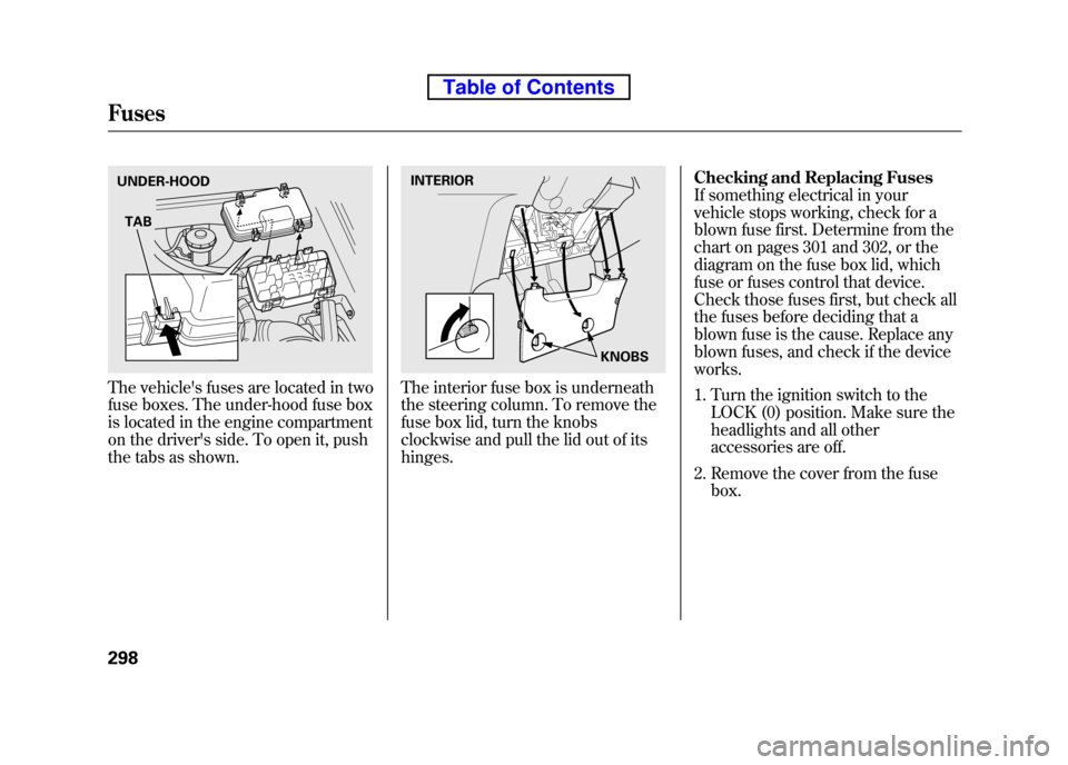
The vehicle's fuses are located in two
fuse boxes. The under-hood fuse box
is located in the engine compartment
on the driver's side. To open it, push
the tabs as shown.The interior fuse box is underneath
the steering column. To remove the
fuse box lid, turn the knobs
clockwise and pull the lid out of itshinges.Checking and Replacing Fuses
If something electrical in your
vehicle stops working, check for a
blown fuse first. Determine from the
chart on pages 301 and 302, or the
diagram on the fuse box lid, which
fuse or fuses control that device.
Check those fuses first, but check all
the fuses before deciding that a
blown fuse is the cause. Replace any
blown fuses, and check if the deviceworks.
1. Turn the ignition switch to the
LOCK (0) position. Make sure the
headlights and all other
accessories are off.
2. Remove the cover from the fuse box.
UNDER-HOOD
TABINTERIOR
KNOBS
Fuses
298
Table of Contents
Page 326 of 342

Air ConditioningRefrigerant type HFC-134a (R-134a)
Charge quantity 17.6 -19.4 oz (500 -550 g)
Lubricant type ND-OIL8
Lights Headlights 12 V -60/55 W (H4/HB2)
Daytime running lights 12 V -60 W (HB3)
Front turn signal/parking lights 12 V -27/8 W (Amber)
Front side marker lights 12 V -3CP
Side turn signal lights 12 V -3CP
Rear turn signal lights 12 V -21 W (Amber)
Rear side marker lights 12 V -3CP
Brake/Taillights 12 V -21/5 W
Back-up lights 12 V -21 CP
License plate lights 12 V -5W
Ceiling light 12 V -8W
ꭧ1
12 V -5Wꭧ2, ꭧ3
Spotlights 12 V -8Wꭧ2, ꭧ3
Cargo area light 12 V -8W
High-mount brake light 12 V -21 W
Battery Capacity 12 V -47 AH/20 HR
12 V -38 AH/5 HR Fuses
Interior See page 301 or the fuse label attached to the inside of the fuse
box door under the steering column.
Under-hood See page 302 or the fuse box cover.
Alignment Toe-in Front 0.0 in (0 mm)
Rear 0.08 in (2.0 mm)
Camber Front -0°13 ’
ꭧ1, ꭧ2
- 0°24 ’ꭧ3
Rear -1°00 ’ꭧ1, ꭧ2
- 1°06 ’ꭧ3
Caster Front 1°50 ’
Tires Size Front/Rear P215/70R16 99S
ꭧ 1, ꭧ2
P225/55R18 97Hꭧ3
Pressure Front 33 psi (230 kPa, 2.3 kgf/cm2)ꭧ 1, ꭧ2
32 psi (220 kPa, 2.2 kgf/cm2)ꭧ 3
Rear 35 psi (240 kPa, 2.4 kgf/cm2)ꭧ1, ꭧ2
32 psi (220 kPa, 2.2 kgf/cm2)ꭧ 3
Spare 60 psi (420 kPa, 4.2 kgf/cm2)
ꭧ 1: LX model
ꭧ 2: EX model
ꭧ 3: SC model
Specifications
310
Table of Contents