turn signal HONDA ELEMENT 2010 1.G Owner's Manual
[x] Cancel search | Manufacturer: HONDA, Model Year: 2010, Model line: ELEMENT, Model: HONDA ELEMENT 2010 1.GPages: 342, PDF Size: 5.76 MB
Page 279 of 342

4. Insert the new bulb into the hole,and turn it one-quarter turn
clockwise to lock it in place.
5. Push the electrical connector back onto the bulb. Make sure it is on
all the way.
6. Test the lights to make sure the new bulb is working. Replacing a Front Parking/Turn
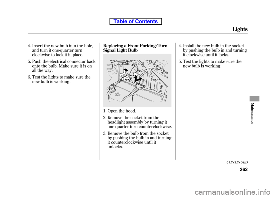
Signal Light Bulb
1. Open the hood.
2. Remove the socket from the
headlight assembly by turning it
one-quarter turn counterclockwise.
3. Remove the bulb from the socket by pushing the bulb in and turning
it counterclockwise until itunlocks. 4. Install the new bulb in the socket
by pushing the bulb in and turning
it clockwise until it locks.
5. Test the lights to make sure the new bulb is working.
CONTINUED
Lights
263
Maintenance
Table of Contents
Page 280 of 342

Replacing a Side Turn Signal Bulb
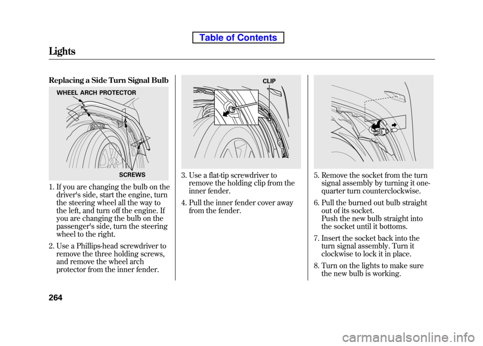
1. If you are changing the bulb on thedriver's side, start the engine, turn
the steering wheel all the way to
the left, and turn off the engine. If
you are changing the bulb on the
passenger's side, turn the steering
wheel to the right.
2. Use a Phillips-head screwdriver to remove the three holding screws,
and remove the wheel arch
protector from the inner fender.
3. Use a flat-tip screwdriver toremove the holding clip from the
inner fender.
4. Pull the inner fender cover away from the fender.5. Remove the socket from the turnsignal assembly by turning it one-
quarter turn counterclockwise.
6. Pull the burned out bulb straight out of its socket.
Push the new bulb straight into
the socket until it bottoms.
7. Insert the socket back into the turn signal assembly. Turn it
clockwise to lock it in place.
8. Turn on the lights to make sure the new bulb is working.
WHEEL ARCH PROTECTOR
SCREWS
CLIP
Lights
264
Table of Contents
Page 282 of 342

Replacing Rear Bulbs
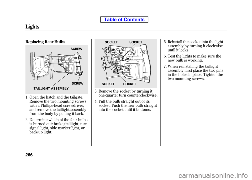
1. Open the hatch and the tailgate.Remove the two mounting screws
with a Phillips-head screwdriver,
and remove the taillight assembly
from the body by pulling it back.
2. Determine which of the four bulbs is burned out: brake/taillight, turn
signal light, side marker light, or
back-up light.
3. Remove the socket by turning itone-quarter turn counterclockwise.
4. Pull the bulb straight out of its socket. Push the new bulb straight
into the socket until it bottoms. 5. Reinstall the socket into the light
assembly by turning it clockwise
until it locks.
6. Test the lights to make sure the new bulb is working.
7. When reinstalling the taillight assembly, first place the two pins
in the holes in place. Tighten the
two mounting screws.
SCREW
SCREW
TAILLIGHT ASSEMBLY
SOCKET SOCKET
SOCKET
SOCKET
Lights
266
Table of Contents
Page 317 of 342

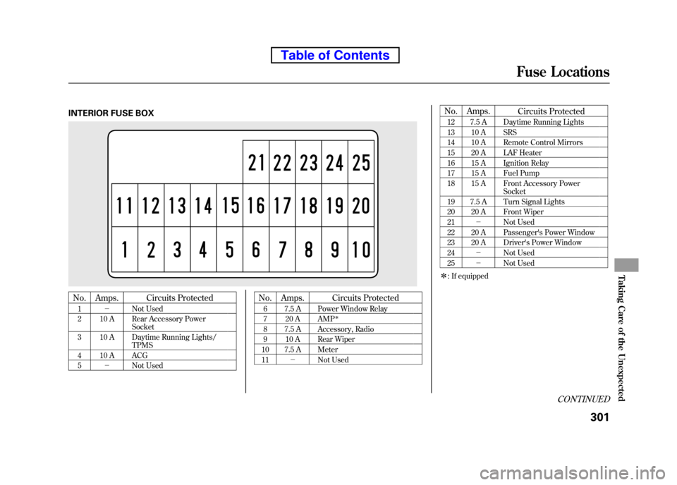
INTERIOR FUSE BOX
No.Amps. Circuits Protected
1 - Not Used
2 10 A Rear Accessory Power Socket
3 10 A Daytime Running Lights/ TPMS
4 10 A ACG 5 - Not Used No. Amps.
Circuits Protected
6 7.5 A Power Window Relay
7 20 A AMP
ꭧ
8 7.5 A Accessory, Radio
9 10 A Rear Wiper
10 7.5 A Meter11 - Not Used No. Amps.
Circuits Protected
12 7.5 A Daytime Running Lights
13 10 A SRS
14 10 A Remote Control Mirrors
15 20 A LAF Heater
16 15 A Ignition Relay
17 15 A Fuel Pump
18 15 A Front Accessory Power Socket
19 7.5 A Turn Signal Lights
20 20 A Front Wiper21 - Not Used
22 20 A Passenger's Power Window
23 20 A Driver's Power Window 24 - Not Used
25 - Not Used
ꭧ : If equipped
CONTINUED
Fuse Locations
301
Taking Care of the Unexpected
Table of Contents
Page 326 of 342

Air ConditioningRefrigerant type HFC-134a (R-134a)
Charge quantity 17.6 -19.4 oz (500 -550 g)
Lubricant type ND-OIL8
Lights Headlights 12 V -60/55 W (H4/HB2)
Daytime running lights 12 V -60 W (HB3)
Front turn signal/parking lights 12 V -27/8 W (Amber)
Front side marker lights 12 V -3CP
Side turn signal lights 12 V -3CP
Rear turn signal lights 12 V -21 W (Amber)
Rear side marker lights 12 V -3CP
Brake/Taillights 12 V -21/5 W
Back-up lights 12 V -21 CP
License plate lights 12 V -5W
Ceiling light 12 V -8W
ꭧ1
12 V -5Wꭧ2, ꭧ3
Spotlights 12 V -8Wꭧ2, ꭧ3
Cargo area light 12 V -8W
High-mount brake light 12 V -21 W
Battery Capacity 12 V -47 AH/20 HR
12 V -38 AH/5 HR Fuses
Interior See page 301 or the fuse label attached to the inside of the fuse
box door under the steering column.
Under-hood See page 302 or the fuse box cover.
Alignment Toe-in Front 0.0 in (0 mm)
Rear 0.08 in (2.0 mm)
Camber Front -0°13 ’
ꭧ1, ꭧ2
- 0°24 ’ꭧ3
Rear -1°00 ’ꭧ1, ꭧ2
- 1°06 ’ꭧ3
Caster Front 1°50 ’
Tires Size Front/Rear P215/70R16 99S
ꭧ 1, ꭧ2
P225/55R18 97Hꭧ3
Pressure Front 33 psi (230 kPa, 2.3 kgf/cm2)ꭧ 1, ꭧ2
32 psi (220 kPa, 2.2 kgf/cm2)ꭧ 3
Rear 35 psi (240 kPa, 2.4 kgf/cm2)ꭧ1, ꭧ2
32 psi (220 kPa, 2.2 kgf/cm2)ꭧ 3
Spare 60 psi (420 kPa, 4.2 kgf/cm2)
ꭧ 1: LX model
ꭧ 2: EX model
ꭧ 3: SC model
Specifications
310
Table of Contents