fuel HONDA HR-V 2017 2.G Quick Guide
[x] Cancel search | Manufacturer: HONDA, Model Year: 2017, Model line: HR-V, Model: HONDA HR-V 2017 2.GPages: 78, PDF Size: 5.33 MB
Page 4 of 78
| 1
V
ISUAL
I
NDEX
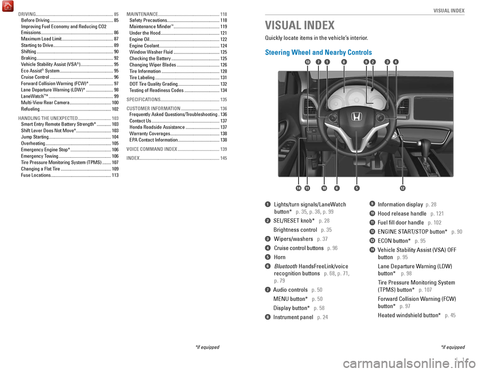
Quickly locate items in the vehicle’s interior.
Steering Wheel and Nearby Controls
1 Lights/turn signals/LaneW
atch
button* p. 35, p. 36, p. 99
2 SEL/RESET knob* p. 28
Brightness control
p. 35
3 Wipers/washers p. 37
4 Cruise control buttons p. 96
5 Horn
6 Bluetooth HandsFreeLink/voice
recognition buttons
p. 68, p. 71,
p. 79
7 Audio controls p. 50
MENU button*
p. 50
Display button*
p. 58
8 Instrument panel p. 24
9 Information display p. 28
10 Hood release handle p. 121
11 Fuel fill door handle p. 102
12 ENGINE START/STOP button* p. 90
13 ECON button* p. 95
14 Vehicle Stability Assist (VSA) OFF
button
p. 95
Lane Departure W
arning (LDW)
button*
p. 98
T
ire Pressure Monitoring System
(TPMS) button*
p. 107
Forward Collision W
arning (FCW)
button*
p. 97
Heated windshield button*
p. 45
VISUAL INDEX
*if equipped
*if equipped
82
1456121011
1713394
DRIVING....................................................................... 85
Before Driving .......................................................... 85
Improving Fuel Economy and Reducing CO2
Emissions
.................................................................. 86
Maximum Load Limit
............................................... 87
Starting to Drive
....................................................... 89
Shifting
...................................................................... 90
Braking
...................................................................... 92
Vehicle Stability Assist (VSA
®) .............................. 95
Eco Assist® System ................................................. 95
Cruise Control .......................................................... 96
Forward Collision Warning (FCW)*
......................97
Lane Departure Warning (LDW)*
.........................98
LaneWatch
™* ........................................................... 99
Multi-View Rear Camera ...................................... 100
Refueling
................................................................. 102
HANDLING THE UNEXPECTED
.............................. 103
Smart Entry Remote Battery Strength*
.............103
Shift Lever Does Not Move*
................................ 103
Jump Starting
......................................................... 104
Overheating
............................................................ 105
Emergency Engine Stop*
..................................... 106
Emergency Towing
................................................ 106
T
ire Pressure Monitoring System (TPMS) ........107
Changing a Flat Tire
.............................................. 109
Fuse Locations
....................................................... 113MAINTENANCE
........................................................
118
Safety Precautions
................................................
118
Maintenance Minder™ .......................................... 119
Under the Hood
...................................................... 121
Engine Oil
................................................................ 122
Engine Coolant
....................................................... 124
Window Washer Fluid
.......................................... 125
Checking the Battery
............................................ 125
Changing Wiper Blades
....................................... 126
Tire Information
..................................................... 128
Tire Labeling
........................................................... 131
DOT Tire Quality Grading
...................................... 132
T
esting of Readiness Codes ................................ 134
SPECIFICATIONS...................................................... 135 CUSTOMER INFORMATION
................................... 136
Frequently Asked Questions/Troubleshooting
.136
Contact Us
.............................................................. 137
Honda Roadside Assistance
............................... 137
Warranty Coverages
............................................. 138
EP
A Contact Information ...................................... 138
VOICE COMMAND INDEX
...................................... 139
INDEX
........................................................................\
. 145
Page 16 of 78
24 || 25
I NSTRUMENT P
ANELI
NSTRUMENT P
ANEL
Malfunction indicator lamp (check engine light)
• The emissions control system may have a problem, or the fuel cap is\
loose
or missing.
• (Blinks) A
misfire in the engine’s cylinders is detected. Stop in a safe place,
and wait for the engine to cool down.
Anti-lock Brake System (ABS)
There is a problem with the anti-lock brake system. Your vehicle still has
normal braking ability, but no anti-lock function.
Tire Pressure Monitoring System (TPMS) (U.S. models only)
There is a problem with the tire pressure monitoring system, or the vehi\
cle is
fitted with the compact spare tire.
Forward Collision Warning (FCW)* (Canadian models only)
There is a problem with the FCW system.
Lane Departure Warning (LDW)* (Canadian models only)
There is a problem with the LDW system.
Vehicle Stability Assist (VSA)
There is a problem with the VSA system or hill start assist system.
Brake system
There is a problem with the automatic brake hold system.
Electric parking brake system
There is a problem with the electric parking brake system. Avoid using the
parking brake. Have your vehicle inspected immediately.
Electric Power Steering (EPS)
There is a problem with the EPS system. Stop in a safe place, and restar\
t the
vehicle.
Starter system*
There is a problem with the starter system.
All Wheel Drive (AWD)*
There is a problem with the AWD system. If the indicator blinks, the system
is overheated and inactive. Stop in a safe place, and idle until the ind\
icator
goes off.
High temperature
The engine coolant temperature is high. Drive slowly to prevent overheat\
ing.
If the indicator remains on, immediately stop the vehicle in a safe plac\
e (see
page 105).
Canada U.S.
U.S.
Canada
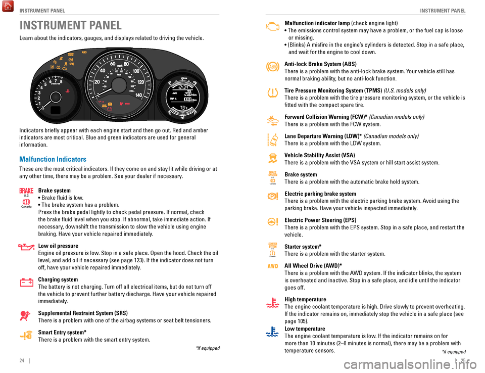
Learn about the indicators, gauges, and displays related to driving the \
vehicle.
Indicators briefly appear with each engine start and then go out. Red \
and amber
indicators are most critical. Blue and green indicators are used for gen\
eral
information.
Malfunction Indicators
These are the most critical indicators. If they come on and stay lit whi\
le driving or at
any other time, there may be a problem. See your dealer if necessary. Brake system
• Brake fluid is low.
• The brake system has a problem.
Press the brake pedal lightly to check pedal pressure. If normal, check \
the brake fluid level when you stop. If abnormal, take immediate actio\
n. If
necessary, downshift the transmission to slow the vehicle using engine
braking. Have your vehicle repaired immediately.
Low oil pressure
Engine oil pressure is low. Stop in a safe place. Open the hood. Check the oil
level, and add oil if necessary (see page 123). If the indicator does \
not turn
off, have your vehicle repaired immediately.
Charging system
The battery is not charging. Turn off all electrical items, but do not turn off
the vehicle to prevent further battery discharge. Have your vehicle repa\
ired
immediately.
Supplemental Restraint System (SRS)
There is a problem with one of the airbag systems or seat belt tensioner\
s.
Smart Entry system*
There is a problem with the smart entry system.
Canada
U.S.
INSTRUMENT PANEL
*if equipped
*if equipped
Low temperature
The engine coolant temperature is low. If the indicator remains on for
more than 10 minutes (2–8 minutes is normal), there may be a proble\
m with
temperature sensors.
Page 17 of 78
26 || 27
I NSTRUMENT P
ANELI
NSTRUMENT P
ANEL
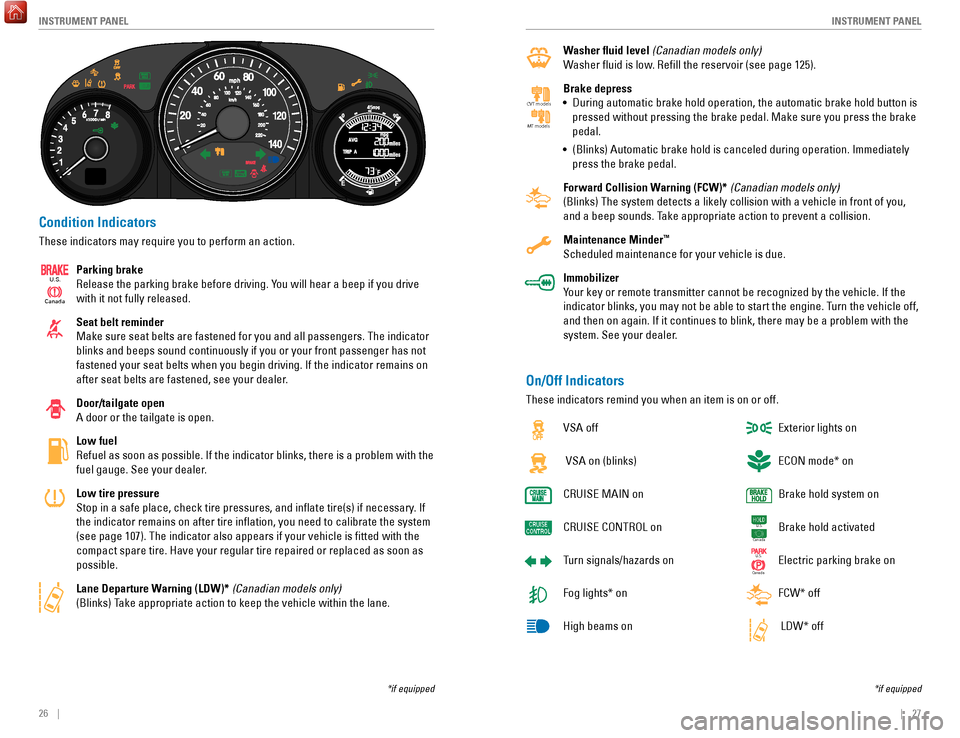
Condition Indicators
These indicators may require you to perform an action.
Parking brake
Release the parking brake before driving. You will hear a beep if you drive
with it not fully released.
Seat belt reminder
Make sure seat belts are fastened for you and all passengers. The indica\
tor
blinks and beeps sound continuously if you or your front passenger has not
fastened your seat belts when you begin driving. If the indicator remain\
s on
after seat belts are fastened, see your dealer.
Door/tailgate open
A door or the tailgate is open.
Low fuel
Refuel as soon as possible. If the indicator blinks, there is a problem \
with the
fuel gauge. See your dealer.
Low tire pressure
Stop in a safe place, check tire pressures, and inflate tire(s) if n\
ecessary. If
the indicator remains on after tire inflation, you need to calibrate t\
he system
(see page 107). The indicator also appears if your vehicle is fitted\
with the
compact spare tire. Have your regular tire repaired or replaced as soon \
as
possible.
Lane Departure Warning (LDW)* (Canadian models only)
(Blinks) Take appropriate action to keep the vehicle within the lane.
Canada
U.S.
*if equipped
Washer fluid level (Canadian models only)
Washer fluid is low. Refill the reservoir (see page 125).
Brake depress
•
During automatic brake hold operation, the automatic brake hold button i\
s
pressed without pressing the brake pedal. Make sure you press the brake \
pedal.
•
(Blinks) Automatic brake hold is canceled during operation. Immediatel\
y
press the brake pedal.
Forward Collision W
arning (FCW)* (Canadian models only)
(Blinks) The system detects a likely collision with a vehicle in front\
of you,
and a beep sounds. Take appropriate action to prevent a collision.
Maintenance Minder
™
Scheduled maintenance for your vehicle is due.
Immobilizer
Your key or remote transmitter cannot be recognized by the vehicle. If th\
e
indicator blinks, you may not be able to start the engine. Turn the vehicle off,
and then on again. If it continues to blink, there may be a problem with\
the
system. See your dealer.
CV T models
MT models
On/Off Indicators
These indicators remind you when an item is on or off.
VSA off
VSA on (blinks)
CRUISE
MAIN on
CRUISE
CONTROL on
Turn signals/hazards on
Fog lights* on
High beams on Exterior lights on
ECON mode* on
Brake hold system on
Brake hold activated
Electric parking brake on
FCW* off
LDW* off
U.S.
Canada
U.S.
Canada
*if equipped
Page 18 of 78
28 || 29
V EHICLE C ONTROLS
I
NSTRUMENT P
ANEL
Information Display
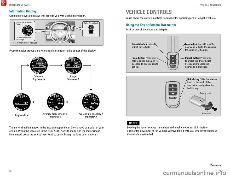
Consists of several displays that provide you with useful information.
Press the select/reset knob to change information in the center of the d\
isplay.
Select/reset knobInstant fuel economy
Clock
Outside temperature
Fuel gauge
These items are always displayed.
Odometer
Trip meter A
Engine oil life Range
Trip meter A
Average fuel economy A Trip meter A
Average fuel economy B
Trip meter B
The meter ring illumination in the instrument panel can be changed to a \
color of your
choice. When the vehicle is in the ACCESSORY or OFF mode and the meter r\
ing is
illuminated, press the select/reset knob to cycle through various color \
options. Learn about the various controls necessary for operating and driving the\
vehicle.
Using the Key or Remote Transmitter
Lock or unlock the doors and tailgate.
VEHICLE CONTROLS
*if equipped
Leaving the key or remote transmitter in the vehicle can result in theft\
or
accidental movement of the vehicle. Always take it with you whenever you\
leave
the vehicle unattended.
NOTICE
Unlock button: Press once
to unlock the driver’s door.
Press again to unlock all
doors and the tailgate.
Built-in key: Slide the release
knob on the back of the
transmitter and pull out the
built-in key.
Lock button: Press to lock the
doors and tailgate. Press again
for audible verification.
Panic button: Press and
hold to sound the alarm for
30 seconds. Press again to
cancel.
Release knob
Built-in key
Tailgate button: Press to
unlock the tailgate.
Page 47 of 78
86 || 87
DRIVING
DRIVING
Improper accessories or modifications can affect your vehicle’s handling, and
stability, and performance, and cause a crash in which you can be seriously
hurt or killed.
Follow all instructions in the vehicle owner’s guide regarding accessories and
modifications.
WARNING
In addition:
•
During the first 600 miles (1,000 km) of operation, avoid sudden acc\
elerat
ion or
full throttle operation so as not to damage the engine or powertrain.
•
A
void hard braking for the first 200 miles (300 km). You should also follow this
when the brake pads are replaced.
Your vehicle has been designed primarily for use on pavement; however, its higher
ground clearance allows you to occasionally travel on unpaved roads. It \
is not
designed for trail-blazing or other challenging off-road activities.
If you decide to drive on unpaved roads, you will find that it require\
s somewhat
different driving skills and that your vehicle will handle somewhat diff\
erently than
it does on pavement. Pay attention to the precautions and tips in this s\
ection, and
get acquainted with your vehicle before leaving the pavement.
Improperly operating this vehicle on or off pavement can cause a crash o\
r
rollover in which you and your passengers can be seriously hurt or kille\
d.
Follow all instructions and guidelines in this guide.
Keep your speed low, and don’t drive faster than conditions permit.
WARNING
Maximum Load Limit
Carrying too much cargo or improperly storing it can affect your vehicle\
’s handling,
stability, stopping distance, and tires, and make it unsafe.
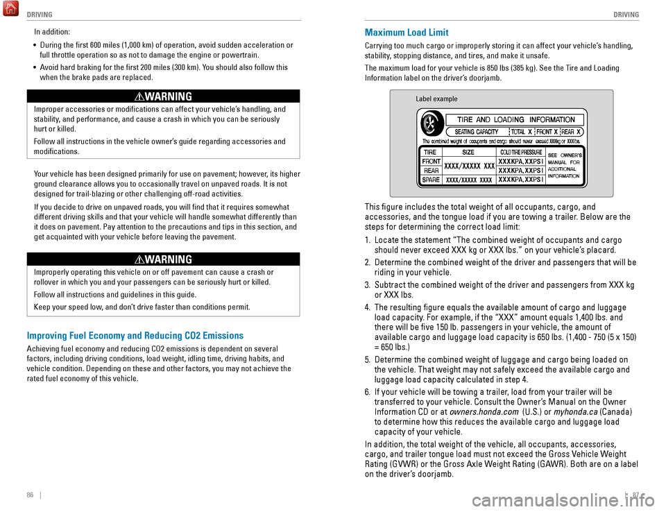
The maximum load for your vehicle is 850 lbs (385 kg). See the Tire and Loading
Information label on the driver’s doorjamb.
Label example
This figure includes the total weight of all occupants, cargo, and
accessories, and the tongue load if you are towing a trailer. Below are the
steps for determining the correct load limit:
1.
Locate the statement “The combined weight of occupants and cargo
should never exceed XXX kg or XXX lbs.” on your vehicle’
s placard.
2.
Determine the combined weight of the driver and passengers that will be \
riding in your vehicle.
3.
Subtract the combined weight of the driver and passengers from XXX kg
or XXX lbs.
4.
The resulting figure equals the available amount of cargo and luggage \
load capacity
. For example, if the “XXX” amount equals 1,400 lbs. and
there will be five 150 lb. passengers in your vehicle, the amount of
available cargo and luggage load capacity is 650 lbs. (1,400 - 750 (5 \
x 150)
= 650 lbs.)
5.
Determine the combined weight of luggage and cargo being loaded on
the vehicle. That weight may not safely exceed the available cargo and
luggage load capacity calculated in step 4.
6.
If your vehicle will be towing a trailer
, load from your trailer will be
transferred to your vehicle. Consult the Owner’s Manual on the Owner
Information CD or at owners.honda.com (U.S.) or myhonda.ca (Canada)
to determine how this reduces the available cargo and luggage load
capacity of your vehicle.
In addition, the total weight of the vehicle, all occupants, accessories\
,
cargo, and trailer tongue load must not exceed the Gross Vehicle Weight
Rating (GVWR) or the Gross Axle Weight Rating (GAWR). Both are on a label
on the driver’s doorjamb.
Improving Fuel Economy and Reducing CO2 Emissions
Achieving fuel economy and reducing CO2 emissions is dependent on severa\
l
factors, including driving conditions, load weight, idling time, driving\
habits, and
vehicle condition. Depending on these and other factors, you may not ach\
ieve the
rated fuel economy of this vehicle.
Page 51 of 78
94 || 95
DRIVING
DRIVING
Automatic Brake Hold
Maintains rear brake hold even after the brake pedal is released. Make sure the
vehicle is on and your seat belt is fastened when operating this feature\
.
1.
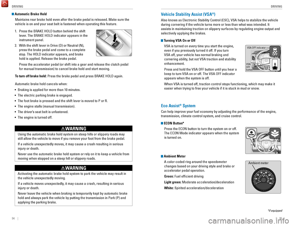
Press the BRAKE HOLD button behind the shift
lever
. The BRAKE HOLD indicator appears in the
instrument panel.
2.
With the shift lever in Drive (D) or Neutral (N),
press the brake pedal and come to a complete
stop. The HOLD indicator appears, and brake
hold is applied. Release the brake pedal.
Press the accelerator pedal (or shift into a gear and release the clutc\
h pedal
for manual transmission) to cancel brake hold and start moving.
T
o turn off brake hold: Press the brake pedal and press BRAKE HOLD again.
Automatic brake hold cancels when:
•
Braking is applied for more than 10 minutes.
•
The electric parking brake is engaged.
•
The foot brake is pressed and the shift lever is moved to P or R.
•
The engine stalls (manual transmission).
•
The driver’
s seat belt is unfastened.
•
The engine is turned off.Using the automatic brake hold system on steep hills or slippery roads m\
ay
still allow the vehicle to move if you remove your foot from the brake p\
edal.
If a vehicle unexpectedly moves, it may cause a crash resulting in serio\
us
injury or death.
Never use the automatic brake hold system or rely on it to keep a vehicl\
e from
moving when stopped on a steep hill or slippery roads.
WARNING
Activating the automatic brake hold system to park the vehicle may resul\
t in
the vehicle unexpectedly moving.
If a vehicle moves unexpectedly, it may cause a crash, resulting in serious
injury or death.
Never leave the vehicle when braking is temporarily kept by automatic brake
hold and always park the vehicle by putting the transmission in Park (P\
) and
applying the parking brake.
WARNING
Vehicle Stability Assist (VSA®)
Also knows as Electronic Stability Control (ESC), VSA helps to stabili\
ze the vehicle
during cornering if the vehicle turns more or less than what was intende\
d. It
assists in maintaining traction on slippery surfaces by regulating engin\
e output and
selectively applying the brakes.
Turning VSA On or Off
VSA is turned on every time you start the engine,
even if you previously turned it off. If you turn
VSA off, your vehicle has normal braking and
cornering ability, but not VSA traction and stability
enhancement.
Press and hold the VSA OFF button until you hear a
beep to turn VSA on or off. The VSA OFF indicator
appears when the system is off.
When VSA is turned off, traction control stops functioning, which may ma\
ke it
easier when trying to free your vehicle if it is stuck in mud or snow.
VSA OFF indicator
VSA
OFF
button
*if equipped
Eco Assist® System
Can help improve your fuel economy by adjusting the performance of the e\
ngine,
transmission, climate control system, and cruise control.
ECON Button* Press the ECON button to turn the system on or off.
The ECON Mode indicator appears when the system
is turned on.
Ambient MeterA color-coded ring around the speedometer
changes based on your driving style and brake or
accelerator pedal operation.
Green: Fuel efficient driving
Light green: Moderate acceleration/deceleration
White: Spirited acceleration/deceleration
Ambient meter
Page 55 of 78
102 || 103
HANDLING THE UNEXPECTED
DRIVING
Refueling
Use the proper fuel and refueling procedure to ensure the best performan\
ce and
safety of your vehicle.
Fuel Information
Use of unleaded gasoline of 87 octane or higher is recommended.
•
Honda recommends TOP TIER Detergent Gasoline where available.
•
Do NOT use gasoline containing more than 15% ethanol.
•
Do NOT use gasoline containing methanol.
•
Do NOT use gasoline containing MMT
. Learn about what to do in critical or emergency situations.Smart Entry Remote Battery Strength*
If the battery life in your remote transmitter is weak, follow the below\
steps to start
the engine.
1.
T
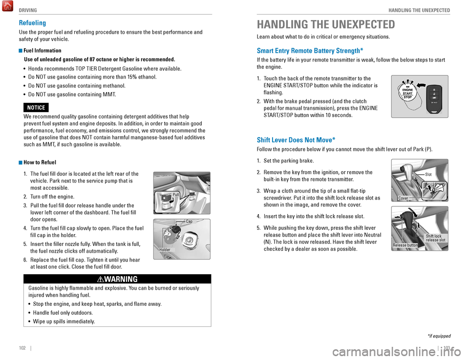
ouch the back of the remote transmitter to the
ENGINE START/STOP button while the indicator is
flashing.
2.
With the brake pedal pressed (and the clutch
pedal for manual transmission), press the ENGINE
ST
ART/STOP button within 10 seconds.
HANDLING THE UNEXPECTED
*if equipped
We recommend quality gasoline containing detergent additives that help
prevent fuel system and engine deposits. In addition, in order to mainta\
in good
performance, fuel economy, and emissions control, we strongly recommend the
use of gasoline that does NOT contain harmful manganese-based fuel addit\
ives
such as MMT, if such gasoline is available.
NOTICE
Gasoline is highly flammable and explosive. You can be burned or seriously
injured when handling fuel.
•
Stop the engine, and keep heat, sparks, and flame away
.
•
Handle fuel only outdoors.
•
Wipe up spills immediately
.
WARNING
How to Refuel1.
The fuel fill door is located at the left rear of the
vehicle. Park next to the service pump that is
most accessible.
2.
T
urn off the engine.
3.
Pull the fuel fill door release handle under the
lower left corner of the dashboard. The fuel fill
door opens.
4.
T
urn the fuel fill cap slowly to open. Place the fuel
fill cap in the holder.
5.
Insert the filler nozzle fully
. When the tank is full,
the fuel nozzle clicks off automatically.
6.
Replace the fuel fill cap. T
ighten it until you hear
at least one click. Close the fuel fill door.
Pull
Holder Cap
Shift Lever Does Not Move*
Follow the procedure below if you cannot move the shift lever out of Par\
k (P).
1.
Set the parking brake.
2.
Remove the key from the ignition, or remove the
built-in key from the remote transmitter
.
3.
W
rap a cloth around the tip of a small flat-tip
screwdriver. Put it into the shift lock release slot as
shown in the image, and remove the cover.
4.
Insert the key into the shift lock release slot.
5.
While pushing the key down, press the shift lever
release button and place the shift lever into Neutral
(N). The lock is now released. Have the shift lever
checked by a dealer as soon as possible.
Slot
Release button Shift lock
release slot
Cover
Page 58 of 78
108 || 109
HANDLING THE UNEXPECTED
HANDLING THE UNEXPECTED
Tire Pressure Monitoring System (TPMS) — Required Federal
Explanation
U.S. models only
Each tire, including the spare (if provided), should be checked monthl\
y
when cold and inflated to the inflation pressure recommended by the \
vehicle manufacturer on the vehicle placard or tire inflation pressure\
label.
(If your vehicle has tires of a different size than the size indicated \
on the
vehicle placard or tire inflation pressure label, you should determine\
the
proper tire inflation pressure for those tires.)
As an added safety feature, your vehicle has been equipped
with a tire pressure monitoring system (TPMS) that illuminates
a low tire pressure telltale when one or more of your tires is
significantly under-inflated.
Accordingly, when the low tire pressure telltale illuminates, you should
stop and check your tires as soon as possible, and inflate them to the\
proper pressure.
Driving on a significantly under-inflated tire causes the tire to overheat
and can lead to tire failure. Under-inflation also reduces fuel efficiency
and tire tread life, and may affect the vehicle’s handling and stopping
ability.
Please note that the TPMS is not a substitute for proper tire maintenanc\
e,
and it is the driver’s responsibility to maintain correct tire pressure, even
if under-inflation has not reached the level to trigger illumination of the
TPMS low tire pressure telltale.
Your vehicle has also been equipped with a TPMS malfunction indicator
to indicate when the system is not operating properly. The TPMS
malfunction indicator is combined with the low tire pressure telltale.
When the system detects a malfunction, the telltale will flash for
approximately one minute and then remain continuously illuminated. This \
sequence will continue upon subsequent vehicle start-ups as long as the \
malfunction exists.
When the malfunction indicator is illuminated, the system may not be abl\
e
to detect or signal low tire pressure as intended.
TPMS malfunctions may occur for a variety of reasons, including the
installation of replacement or alternate tires or wheels on the vehicle \
that
prevent the TPMS from functioning properly.
Always check the TPMS malfunction telltale after replacing one or
more tires or wheels on your vehicle to ensure that the replacement
or alternate tires and wheels allow the TPMS to continue to function
properly.Changing a Flat Tire
If a tire goes flat while driving, grasp the steering wheel firmly, and brake gradually
to reduce speed. Then, stop in a safe place. Replace the flat tire wit\
h the compact
spare tire. Go to a dealer as soon as possible to have the full-size tir\
e repaired or
replaced.
Getting Ready to Change the Tire
Park the vehicle on a firm, level, and non-slippery surface. Apply the\
parking
brake, shift to Park (P), and turn the vehicle off. Turn on the hazard warning lights.
1.
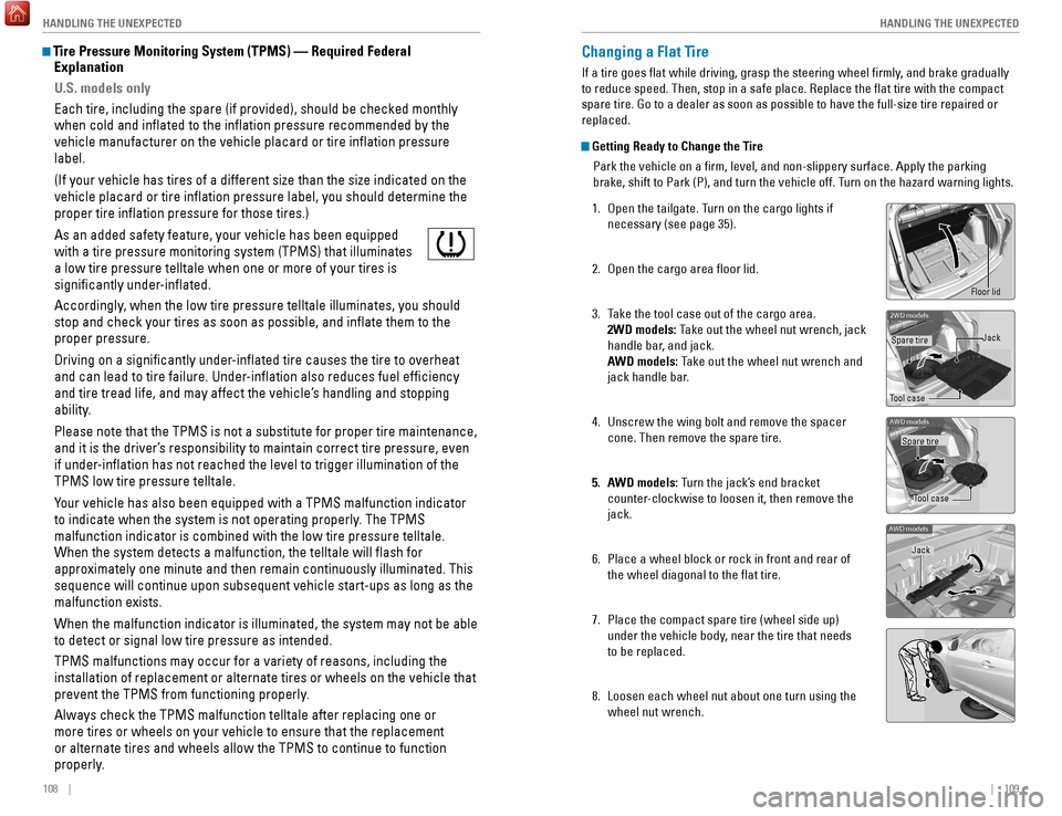
Open the tailgate. T
urn on the cargo lights if
necessary (see page 35).
2.
Open the cargo area floor lid.
3.
T
ake the tool case out of the cargo area.
2WD models: Take out the wheel nut wrench, jack
handle bar, and jack.
AWD models: Take out the wheel nut wrench and
jack handle bar.
4.
Unscrew the wing bolt and remove the spacer
cone. Then remove the spare tire.
5.
A
WD models: Turn the jack’s end bracket
counter-clockwise to loosen it, then remove the
jack.
6.
Place a wheel block or rock in front and rear of
the wheel diagonal to the flat tire.
7.
Place the compact spare tire (wheel side up)
under the vehicle body
, near the tire that needs
to be replaced.
8.
Loosen each wheel nut about one turn using the
wheel nut wrench.
2WD model s
Tool caseSpare tire
Jack
AWD models
Tool case
Spare tire
AWD models
Jack
Floor lid
Page 61 of 78
114 || 115
HANDLING THE UNEXPECTED
HANDLING THE UNEXPECTED
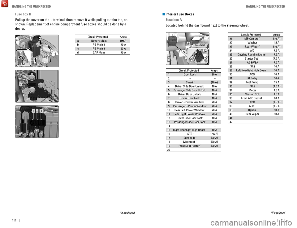
Fuse box B
Pull up the cover on the + terminal, then remove it while pulling out th\
e tab, as
shown. Replacement of engine compartment fuse boxes should be done by a \
dealer.
Circuit Protecte dAmpsaBattery Main100 AbRB Main 170AcRB Main 280 AdCAP Main70 A
Ta b
*if equipped
a
b c d
Circuit ProtectedAmps1Door Lock20 A2––3Smart*(10 A)4Driver Side Door Unlock10 A5Passenger Side Door Unlock10 A6Driver Door Unlock10A7Driver Door Lock10A8Driver’s Power Window20A9Passenger’s Power Window20A10Rear Left Power Window20A11Rear Right Power Window20A12Driver Side Door Lock10A13Passenger Side Door Lock10A14––15Right Headlight High Beam10A16STS*(7.5 A)17Sunshad e*(20A )18Moonroof*(20A )19Front Seat Heater*(20A )20––
Circuit Protecte dAmps
21 MP Camera*(10 A)
22 Washer 15A
23 Rear Wiper
*(10 A)
24 A/C 7.5 A
25 Daytime Running Light s7.5 A
26 Starter Cut
*(7.5 A)
27 ABS/VSA 7.5 A
28 SRS 10A
29 Left Headlight High Beam 10A
30 ACG 10A
31 IG Relay 10 A
32 Fuel Pump 15A
33 SRS (7.5 A)
34 Meter 7.5 A
35 Mission SOL 7.5 A
36 Front ACC Socket 20A
37 ACC (7.5 A)
38 ACC
*(7.5 A)
39 Option 10A
40 Rear Wiper 10 A
41 � �
42 � �
Interior Fuse Boxes
Fuse box A
Located behind the dashboard next to the steering wheel.
*if equipped
Fuse label
Circuit Protected Amps
1 Door Lock 20 A
2 – –
3 Smart
*(10 A)
4 Driver Side Door Unlock 10 A
5
Passenger Side Door Unlock10 A
6 Driver Door Unlock 10A
7 Driver Door Lock 10A
8 Driver’s Power Window 20A
9 Passenger’s Power Window 20A
10 Rear Left Power Window 20A
11 Rear Right Power Window 20A
12 Driver Side Door Lock 10A
13 Passenger Side Door Lock 10A
14 – –
15 Right Headlight High Beam 10A
16 STS
*(7.5 A)
17 Sunshade*(20A )
18 Moonroof*(2 0A )
19 Front Seat Heater*(20A )
20 – –
Circuit ProtectedAmps21MP Camera*(10 A)22Washer15A23Rear Wipe r*(10 A)24A/C7.5 A25Daytime Running Light s7.5 A26Starter Cut*(7.5 A)27ABS/VSA7.5 A28SRS10A29Left Headlight High Beam10A30ACG10A31IG Rela y10 A32Fuel Pump15 A33SRS(7.5 A)34Meter7.5 A35Mission SOL7.5 A36Front ACC Socket20A37ACC(7.5 A)38ACC*(7.5 A)39Optio n10A40Rear Wiper10 A41��42��
Page 63 of 78
118 || 119
MAINTENANCE
MAINTENANCE
Learn about basic maintenance that you can perform on the vehicle yourse\
lf, as well
as information about how to best maintain the vehicle.
Safety Precautions
Some of the most important safety precautions are listed below; however, we cannot
warn you of every conceivable hazard that can arise in performing mainte\
nance.
Only you can decide whether or not you should perform a given task.
Maintenance Safety
•
T
o reduce the possibility of fire or explosion, keep cigarettes, sparks\
, and flames
away from the battery and all fuel-related parts.
•
Never leave rags, towels, or other flammable objects under the hood. H\
eat
from
the engine and exhaust can ignite them, causing a fire.
•
T
o clean parts, use a commercially available degreaser or parts cleaner, not
gasoline.
•
W
ear eye protection and protective clothing when working with the battery\
or
compressed air.
•
Do not run the engine in confined spaces where carbon monoxide gas can\
accumulate.
Vehicle Safety
•
The vehicle must be stationary
, and parked on level ground with the parking
brake set and the engine off.
•
Be aware that hot parts can burn you.
•
Be aware that moving parts can injure you.
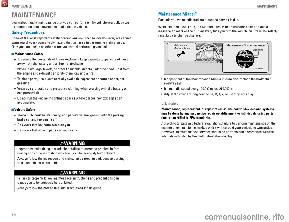
MAINTENANCEMaintenance Minder™
Reminds you when indicated maintenance service is due.
When maintenance is due, the Maintenance Minder indicator comes on and a\
message appears on the display every time you turn the vehicle on. Press\
the select/
reset knob to change displays.
Maintenance
Minder indicator
Main items
Sub items
Maintenance Minder message
• Independent of the Maintenance Minder information, replace the brake fl\
uid
every 3 years.
•
Inspect idle speed every 160,000 miles (256,000 km).
•
Adjust the valves during services A, B, 1, 2, or 3 if they are noisy
.
U.S. models
Maintenance, replacement, or repair of emissions control devices and sys\
tems
may be done by any automotive repair establishment or individuals using \
parts
that are certified to EPA standards.
According to state and federal regulations, failure to perform maintenan\
ce on the
maintenance main items marked with # will not void your emissions warranties.
However, all maintenance services should be performed in accordance with the
intervals indicated by the multi-information display.
Improperly maintaining this vehicle or failing to correct a problem befo\
re
driving can cause a crash in which you can be seriously hurt or killed. \
Always follow the inspection and maintenance recommendations according
to the schedules in this guide.
WARNING
Failure to properly follow maintenance instructions and precautions can \
cause you to be seriously hurt or killed.
Always follow the procedures and precautions in this guide.
WARNING