port HONDA INSIGHT 2020 Owner's Manual (in English)
[x] Cancel search | Manufacturer: HONDA, Model Year: 2020, Model line: INSIGHT, Model: HONDA INSIGHT 2020Pages: 675, PDF Size: 36.95 MB
Page 555 of 675
553
uuBefore Performing Maintenance uSafety When Performing Maintenance
Continued
Maintenance
Safety When Performing Maintenance
Some of the most important safety precau tions are given here. However, we cannot
warn you of every conceivable hazard that can arise in performing maintenance.
Only you can decide whether you should perform a given task.
• To reduce the possibility of fire or explos ion, keep cigarettes, sparks, and flames
away from the 12-volt battery, all High Volt age system, and all fuel related parts.
• Never leave rags, towels, or other flammable objects under the hood.
u Heat from the engine and exhaust can ignite them, causing a fire.
• To clean parts, use a co mmercially available degreaser or parts cleaner, not
gasoline.
• Wear eye protection and pr otective clothing when working with the 12-volt
battery or compressed air.
• Engine exhaust contains carbon monoxide, which is poisonous and can kill you.
u Only operate the engine if th ere is sufficient ventilation.
■Maintenance Safety
1Safety When Performing Maintenance
3WARNING
Improperly maintaining this vehicle or
failing to correct a pr oblem before driving
can cause a crash in which you can be
seriously hurt or killed.
Always follow the inspection and
maintenance recommendations according
to the schedules in this owner’s manual.
3WARNING
Failure to properly follow maintenance
instructions and prec autions can cause you
to be seriously hurt or killed.
Always follow the procedures and
precautions in this owner’s manual.
20 INSIGHT-31TXM6100.book 553 ページ 2019年4月24日 水曜日 午後2時2分
Page 565 of 675
563
uuMaintenance Under the Hood uOpening the Hood
Maintenance
Opening the Hood
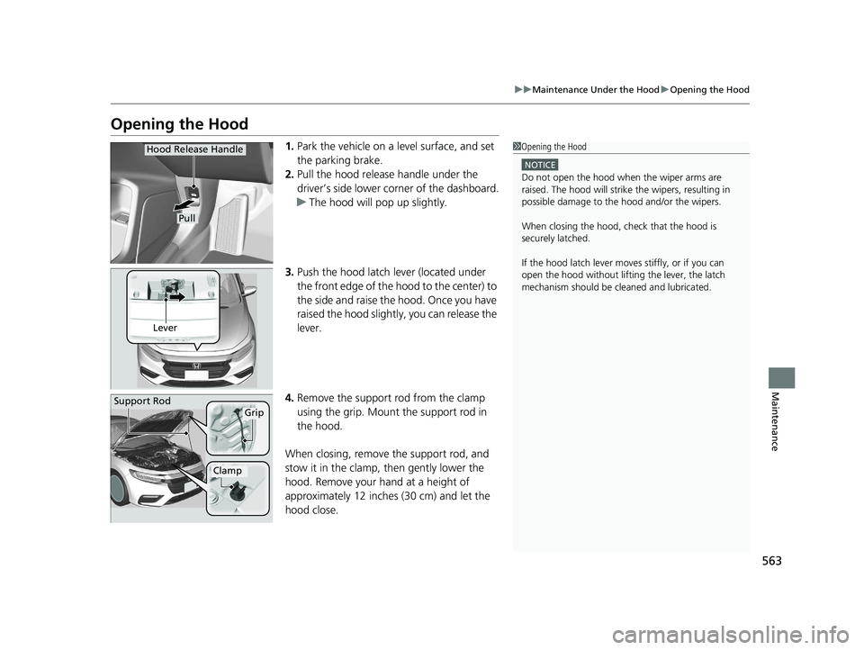
1. Park the vehicle on a level surface, and set
the parking brake.
2. Pull the hood release handle under the
driver’s side lower corner of the dashboard.
u The hood will pop up slightly.
3. Push the hood latch lever (located under
the front edge of the hood to the center) to
the side and raise the hood. Once you have
raised the hood slightly, you can release the
lever.
4. Remove the support rod from the clamp
using the grip. Mount the support rod in
the hood.
When closing, remove the support rod, and
stow it in the clamp, then gently lower the
hood. Remove your hand at a height of
approximately 12 inches (30 cm) and let the
hood close.1 Opening the Hood
NOTICE
Do not open the hood when the wiper arms are
raised. The hood will strike the wipers, resulting in
possible damage to the hood and/or the wipers.
When closing the hood, check that the hood is
securely latched.
If the hood latch lever moves stiffly, or if you can
open the hood without lifti ng the lever, the latch
mechanism should be cl eaned and lubricated.
Hood Release Handle
Pull
Lever
Support RodGrip
Clamp
20 INSIGHT-31TXM6100.book 563 ページ 2019年4月24日 水曜日 午後2時2分
Page 586 of 675
uuChecking and Maintaining Tires uTire Labeling
584
Maintenance
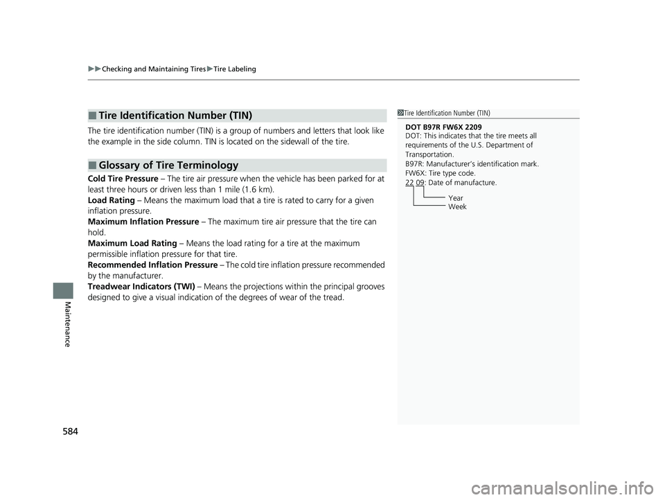
The tire identification number (TIN) is a group of numbers and letters that look like
the example in the side co lumn. TIN is located on the sidewall of the tire.
Cold Tire Pressure – The tire air pressure when the vehicle has been parked for at
least three hours or driven less than 1 mile (1.6 km).
Load Rating – Means the maximum load that a ti re is rated to carry for a given
inflation pressure.
Maximum Inflation Pressure – The maximum tire air pressure that the tire can
hold.
Maximum Load Rating – Means the load rating for a tire at the maximum
permissible inflation pr essure for that tire.
Recommended Inflation Pressure – The cold tire inflation pressure recommended
by the manufacturer.
Treadwear Indicators (TWI) – Means the projections within the principal grooves
designed to give a visual indication of the degrees of wear of the tread.
■Tire Identification Number (TIN)
■Glossary of Tire Terminology
1 Tire Identification Number (TIN)
DOT B97R FW6X 2209
DOT: This indicates that the tire meets all
requirements of the U.S. Department of
Transportation.
B97R: Manufacturer’s identification mark.
FW6X: Tire type code.
22 09: Date of manufacture.
Year
Week
20 INSIGHT-31TXM6100.book 584 ページ 2019年4月24日 水曜日 午後2時2分
Page 587 of 675
585
uuChecking and Maintaining Tires uDOT Tire Quality Grading (U.S. Vehicles)
Continued
Maintenance
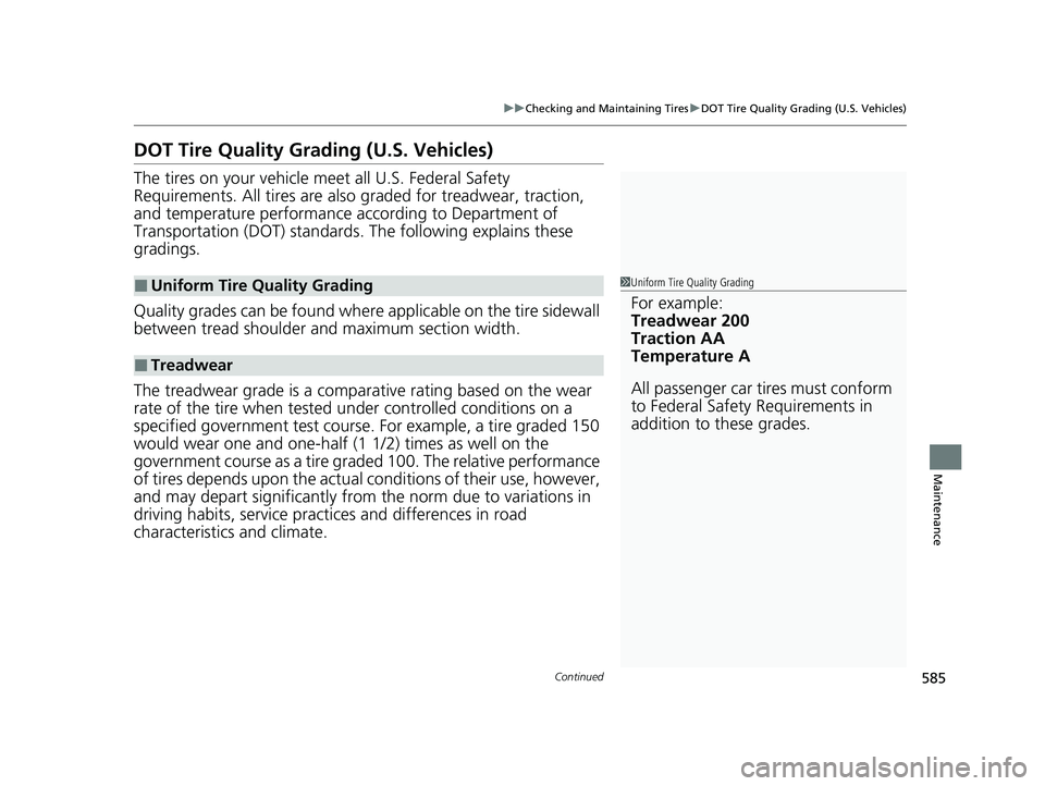
DOT Tire Quality Grading (U.S. Vehicles)
The tires on your vehicle m eet all U.S. Federal Safety
Requirements. All tires are also graded for treadwear, traction,
and temperature performance according to Department of
Transportation (DOT) standards. The following explains these
gradings.
Quality grades can be found where applicable on th e tire sidewall
between tread shoulder and maximum section width.
The treadwear grade is a comparative rating based on the wear
rate of the tire when tested un der controlled conditions on a
specified government test course. For example, a tire graded 150
would wear one and one-half (1 1/2) times as well on the
government course as a tire graded 100. The relative performance
of tires depends upon the actual conditions of their use, however,
and may depart significantly from the norm due to variations in
driving habits, service practi ces and differences in road
characteristics and climate.
■Uniform Tire Quality Grading
■Treadwear
1 Uniform Tire Quality Grading
For example:
Treadwear 200
Traction AA
Temperature A
All passenger car tires must conform
to Federal Safety Requirements in
addition to these grades.
20 INSIGHT-31TXM6100.book 585 ページ 2019年4月24日 水曜日 午後2時2分
Page 594 of 675

592
uu12-Volt Battery uCharging the AGM Battery
Maintenance
Charging the AGM Battery
AGM labeled batteries like those installe d in your vehicle require a compatible
charger to be properly charged. Damage to the battery can result if the battery is
charged improperly or with the wrong equi pment. For more information on how to
charge your vehicle’s AGM battery, consult a dealer.112-Volt Battery
The vehicle stability assist ® (VSA ®) system, vehicle
stability assist ® (VSA ®) OFF, adaptive cruise control
(ACC) with low speed follow, safety support and low
tire pressure/TPMS indicato rs may come on in amber
along with a message in the driver information
interface when you set the power mode to ON after
re-connecting a battery.
Drive a short distance at more than 12 mph (20
km/h). The indicator should go off. If it does not, have
your vehicle checked by a dealer.
3WARNING
• Use of a battery not designed for this
vehicle could cause a hydrogen gas leak
inside the vehicle, resulting in a fire or
explosion that may cause injury or death.
• Only install a 12V AGM battery designed
for use in this vehicle.
• Contact your Honda dealer for more
information.
20 INSIGHT-31TXM6100.book 592 ページ 2019年4月24日 水曜日 午後2時2分
Page 598 of 675
uuCleaning uInterior Care
596
Maintenance
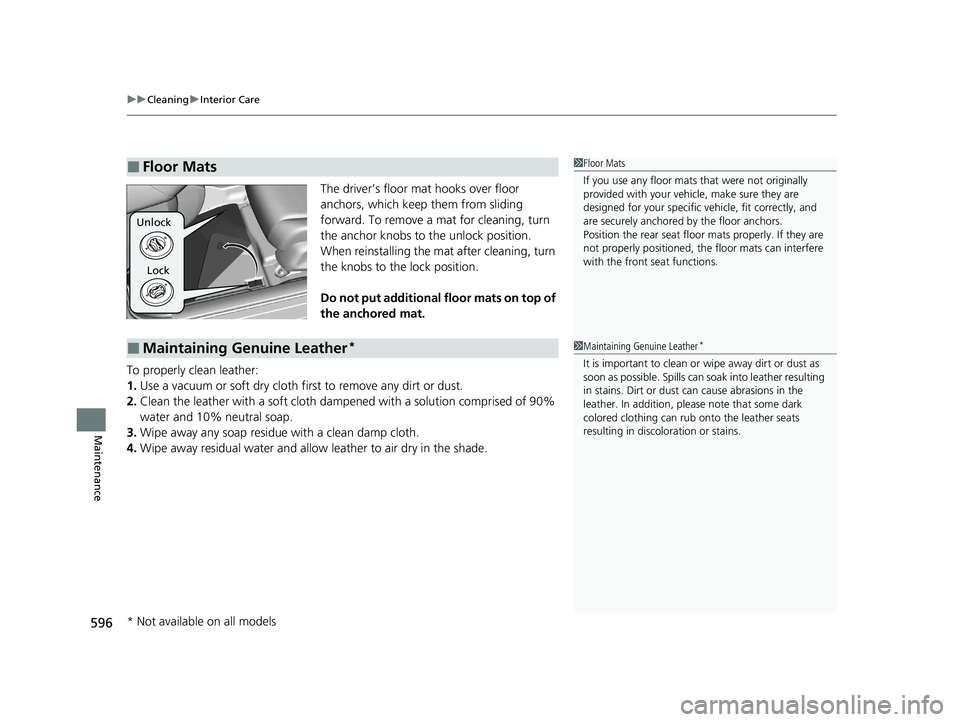
The driver’s floor mat hooks over floor
anchors, which keep them from sliding
forward. To remove a mat for cleaning, turn
the anchor knobs to the unlock position.
When reinstalling the mat after cleaning, turn
the knobs to the lock position.
Do not put additional floor mats on top of
the anchored mat.
To properly clean leather:
1. Use a vacuum or soft dry cloth first to remove any dirt or dust.
2. Clean the leather with a soft cloth dampen ed with a solution comprised of 90%
water and 10% neutral soap.
3. Wipe away any soap residu e with a clean damp cloth.
4. Wipe away residual water and allow leather to air dry in the shade.
■Floor Mats1Floor Mats
If you use any floor mats that were not originally
provided with your vehicle, make sure they are
designed for your specific ve hicle, fit correctly, and
are securely anchored by the floor anchors.
Position the rear seat floor mats properly. If they are
not properly positioned, the floor mats can interfere
with the front seat functions.
Lock
Unlock
■Maintaining Genuine Leather*1
Maintaining Genuine Leather*
It is important to clean or wipe away dirt or dust as
soon as possible. Spills can soak into leather resulting
in stains. Dirt or dust ca n cause abrasions in the
leather. In addition, pl ease note that some dark
colored clothing can rub onto the leather seats
resulting in discol oration or stains.
* Not available on all models
20 INSIGHT-31TXM6100.book 596 ページ 2019年4月24日 水曜日 午後2時2分
Page 604 of 675
602
uuAccessories and Modifications uModifications
Maintenance
Modifications
Do not modify your vehicle in a manner that may affect its handling, stability, or
reliability, or install non-genuine Honda parts or accessories that may have a similar
effect.
Even minor modifications to vehicle system s can affect overall vehicle performance.
Always make sure all equipment is prop erly installed and maintained, and do not
make any modification to your vehicle or its systems that might cause your vehicle
to no longer meet federal, state, prov ince, territory, and local regulations.
The on-board diagnostic port (OBD-II/SAE J1962 connector) installed on this vehicle
is intended to be used with automobile system diagnostic devices or with other
devices that Honda has approved. Use of any other type of device may adversely
affect the vehicle’s electronic systems or allow them to be compromised, possibly
resulting in a system malfunction, drained battery, or other unexpected problems.
Do not modify or attempt to repair your vehicle's high-voltage hybrid power system
or otherwise modify vehicle electrical systems. Disassembling or modifying electrical
equipment can result in a crash or a fire.
If you ever need to replace your vehicle’s high-voltage battery assembly outside of
warranty coverage, we highly recommend that you only use a genuine Honda high-
voltage battery assembly. Genuine Hond a high-voltage battery assemblies are
designed to work with your vehicle’s hybrid power system and have been designed,
engineered and manufactured to avoid ov ercharging situations. Non-genuine high-
voltage battery assemblies may not have be en similarly designed, engineered and
manufactured, and installation of such assemblies could result in overcharging, fires,
loss of power, or other conditions that may increase the likelihood of a crash or
injury.
20 INSIGHT-31TXM6100.book 602 ページ 2019年4月24日 水曜日 午後2時2分
Page 610 of 675
uuIf a Tire Goes Flat uChanging a Flat Tire
608
Handling the Unexpected
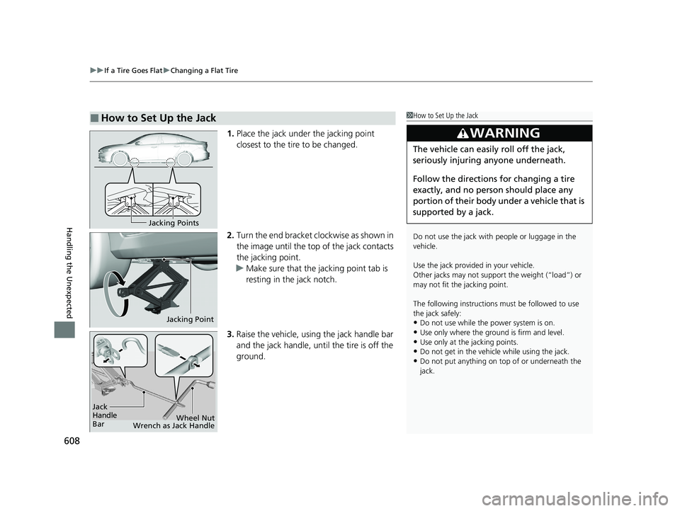
1. Place the jack under the jacking point
closest to the tire to be changed.
2. Turn the end bracket cl ockwise as shown in
the image until the top of the jack contacts
the jacking point.
u Make sure that the jacking point tab is
resting in the jack notch.
3. Raise the vehicle, using the jack handle bar
and the jack handle, until the tire is off the
ground.
■How to Set Up the Jack1How to Set Up the Jack
Do not use the jack with people or luggage in the
vehicle.
Use the jack provided in your vehicle.
Other jacks may not support the weight (“load”) or
may not fit the jacking point.
The following instructions must be followed to use
the jack safely:
•Do not use while the power system is on.
•Use only where the ground is firm and level.•Use only at the jacking points.
•Do not get in the vehicl e while using the jack.
•Do not put anything on top of or underneath the
jack.
3WARNING
The vehicle can easily roll off the jack,
seriously injuring anyone underneath.
Follow the directions for changing a tire
exactly, and no person should place any
portion of their body under a vehicle that is
supported by a jack.
Jacking Points
Jacking Point
Jack
Handle
Bar Wheel Nut
Wrench as Jack Handle
20 INSIGHT-31TXM6100.book 608 ページ 2019年4月24日 水曜日 午後2時2分
Page 632 of 675
uuJump Starting u
630
Handling the Unexpected
Once your vehicle’s engine has started, re move the jumper cables in the following
order.
1. Disconnect the jumper cable from your vehicle’s ground.
2. Disconnect the other end of the jumper cable from the booster battery -
terminal.
3. Disconnect the jumper cable from your vehicle’s jump start box + terminal.
4. Disconnect the other end of the jumper cable from the booster battery +
terminal.
Have your vehicle inspected by a n earby service station or a dealer.
■What to Do After the Engine Starts1What to Do After the Engine Starts
The vehicle stability assist ® (VSA ®) system, vehicles
stability assist ® (VSA ®) OFF, adaptive cruise control
(ACC) with low speed follow, safety support and low
tire pressure/TPMS indicato rs may come on in amber
along with a message in the driver information
interface when you set the power mode to ON after
re-connecting a battery.
Drive a short distance at more than 12 mph (20 km/h).
Each indicator should go off. If any do not, have your
vehicle checked by a dealer.
20 INSIGHT-31TXM6100.book 630 ページ 2019年4月24日 水曜日 午後2時2分
Page 649 of 675
647
Handling the Unexpected
Emergency Towing
Call a professional towing service if you need to tow your vehicle.
■Flat bed equipment
The operator loads your vehicle on the back of a truck.
This is the best way to transport your vehicle.
■Wheel lift equipment
The tow truck uses two pivoti ng arms that go under the front tires and lift them off
the ground. The rear tires remain on the ground. This is an acceptable way to
tow your vehicle.
1 Emergency Towing
NOTICE
Trying to lift or tow your vehicle by the bumpers will
cause serious damage. The bumpers are not designed
to support the vehicle’s weight.
Make sure the parking brake is released. If you
cannot release the parking brake, your vehicle must
be transported by the flat bed equipment. 2 Parking Brake P. 532
NOTICE
Improper towing such as towing behind a
motorhome or other motor vehicle can damage the
transmission.
Never tow your vehicle with just a rope or chain.
It is very dangerous since ropes or chains may shift
from side to side or break.
20 INSIGHT-31TXM6100.book 647 ページ 2019年4月24日 水曜日 午後2時2分