fuse HONDA INTEGRA 1994 4.G Owners Manual
[x] Cancel search | Manufacturer: HONDA, Model Year: 1994, Model line: INTEGRA, Model: HONDA INTEGRA 1994 4.GPages: 1413, PDF Size: 37.94 MB
Page 1236 of 1413
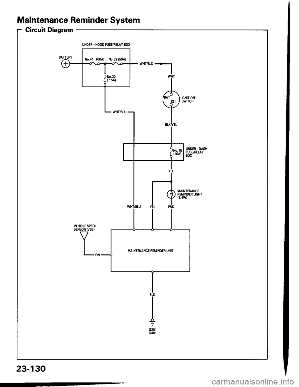
Maintenance Reminder System
Circuit Diagram
23-130
UNDER-HOOD FUSE/REIAY 8OX
MAINIET,IAT,ICE REMINOER UiIIT
Page 1237 of 1413
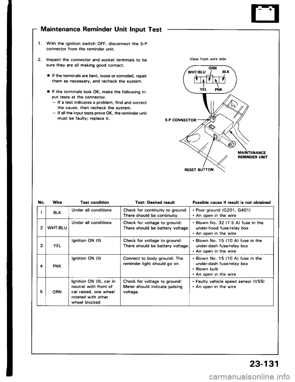
Maintenance Reminder Unit Input Test
1.With the ignition switch OFF, disconnect the 5-P
connector from the reminder unit,
Inspect the connector and socket terminals to be
sufe they are all making good contact.
a lJ the terminals are bent, loose orcorroded, repair
them as necessary, and recheck the svstem.
a It the terminals look OK, make the following in-
Put tests at the connecto..- lf a test indicates a problem, tind and correct
the cause, then recheck the system.- It allthe input tests prove OK, the reminder unit
must be taulty; replace it.
View trom wire side
No.WireTost condltionTest: DaEired rasultPossibl€ cause if result is not obtained
IBLKUnde. all conditionsCheck for continuity to ground:
There should be continuitv.
. Poor ground (G201, G4O1). An open in the wire
WHT/BLU
Under all conditionsCheck tor voltage to ground:
There should be battery voltage
. Blown No. 32 (7.5 A) fuse in the
under-hood tuse/relay box. An open in the wire
YEL
lgnition ON (lllCheck for voltage to ground:
There should be batte.y voltage
. Blown No. 15 (1O A) fuse in the
under-dash fuse/relay box. An open in the wire
4PNK
lgnition ON (ll)Connect to body ground; The
reminder light should go on.
Blown No. 15 (1O A) tuse in the
under-dash fuse/relay box
Blown bulb
An open in the wire
EORN
lgnition ON {ll), car in
neutral with lront ol
car raised, one wheel
rotated with other
wheel blocked
Check for voltage to g.ound:
Meter should indicate pulsing
voltage.
. Faulty vehicle speed sensor (VSS)
. An oDen in the wire
23-131
Page 1239 of 1413
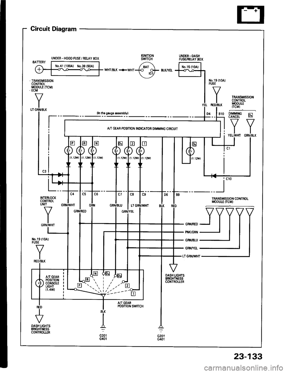
UNOER_HOOD FUSE / REI.AY 8OX
Circuit Diagram
IGNITIONswrTcHUNOER-OASHFUSSREI-AY 8OX
No.19ll0A)FUSE
TMI{SMrSSr0r,lc0IJTRori.IODULEITCMI
fitMritc-;-CANCEL lgll
tlYELTWHT GRN/8L|(
D4
II._l
TRANSMISSIONMODU|.! [TCM}
t
INTERLOCKcoMtRotUNJ]_
IGRT'IMHTo*nn,o_yTT
pr{x/cR1 -J
IGR €|-U -l
GRiITYEt
LT GNNiW{T
No.19 {lFUSE
V
I
I
DASH I-IGHTSBRIGHTNESSCONTROI.IERG2o lG401
I
G201G40t
/-?t ftrt*lwHT/BLX +wHT+ CH- Bl.x/Y€t -+<.\-o+!
y "l
IYEL
lln tho gtugo 8ls€mbvl
AN GEAR POSITION INDICATOR DIMMING CIRCUIT
A/T GEANPOStTt0NcoNsot-ELIGHT0.4w)
M GEARPosrTroN swncH
23-133
Page 1241 of 1413
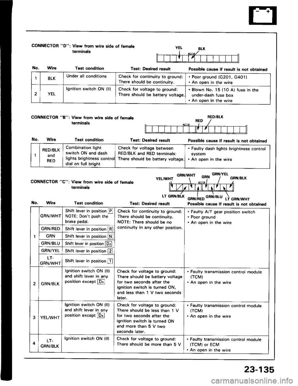
CONNECTOR "D": Visw from wire side ot femals
tetminals
No.WilaTest condition
CONNECTOR "8": View from wire sid6 of fem.l6
i6lminals
No.WileTost condition
CONNECTOR "C": Vi3w lrom wire sido of temale
t6rminals
Test condition
Test: D€sirod rasultPossible cause if result is not obtainod
Tost: D€sir6d resultPossiblo cause if result is not obtained
GRNA HTGRNITELYELAA'HTGRN/BLK
Tost: Desirod r6sult Possible cause it result is not obtainedNo.
BLKUnder all conditionsCheck for continuity to ground:
There should be continuitv.
. Poor ground (G2O1, G4O1). An open in the wire
2YEL
lgnition switch ON { ll}Check for voltage to ground:
There should be battery voltage.
. Blown No. 15 (1O A) tuse in the
under-dash fuse box. An open in the wire
RED/BLK
1
RED/BLK
ano
RED
Combination light
switch ON and dash
lights brighlness control
dial on full bright
Check for voltage between
RED/BLK and RED terminals:
There should be baftery voltage.
. Faulty dash lights b.ightness control
system. An open in the wire
GRN^^/HT
Shift lever in position @NOTE: Don't push the
brake pedal.
Check for continuity to ground:
There should be continuitv.
NOTE: There should be no
continuity in any other position.
Faulty A/T gear position switch
Poor ground
An open in the wire
GRN/REDShift lever in position @
GRNShift lever in position S
GRN/BLUShitr lever in position @
GRN/YELShitt lever in position f2 ]
LT-
GRNMHTShift lever in position E
2GRN/BLK
lgnition switch ON (ll)
and shift lever in anyposition except @
Check for voltage to ground:
There should be battery voltage
for two seconds after the
ignition switch is turned ON,
and less than 1 V two seconds
later.
. Faulty t,ansmission control module(TCM)
. An open in the wire
3YEL/vVHT
lgnition switch ON (ll)
and shitt lever in anyposition except @
Check for voltage to ground:
There should be less than 'l V
tor two seconds after the
ignition switch is turned ON
and more than 5 V two
seconds later.
. Faulty transmission control modute(TCMI
. An open in the wire
4LT.
GRN/BLK
lgnition swirch ON {ll}Check for voltage to ground:
There should be mofe than 5 V
. Faulty transmission control module
ITCM) or ECM. An open in the wire
23-135
Page 1246 of 1413
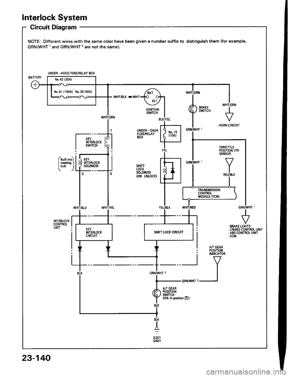
lnterlock System
Circuit Diagram
NOTE: Different wires with the same color have been given a number suffix to distinguish them (tor examplg,
GRNMHT 1 and GRNMHT 2 are not the same).
W}IT/BLK +WHT
Y I if,f,trfi
I i
^'v"'
IIN/vt,H] ,
I
l......................_GRNA,t/r{rz1
/r S'ftiei
f lJlT,ll*n""n,
UNOER -HOOD FUSE/REi.AY BOX
N0.41 (1OCA) No.39 l50A)
THROTTLEPOSITION ITPISENSOR
WHT/GRN
23-140
Page 1247 of 1413
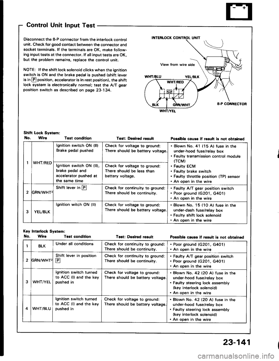
Control Unit Input Test
Oisconnect the 8-P connector from the interlock control
unit. Check for good contact between the connector and
socket terminals. lf the terminals 8re OK, make Iollow-
ing input tests at the connector. lf all input tests are OK,
but the problem remains, replace the cont.ol unit,
NOTE: lf the shilt lock solenoid clicks when the ignition
switch is ON and the brake pedal is pushed (shift tever
is in lfl position, accelerator is in rest position), the shiftlock system is electronically normal; test the A/T gear
positaon switch as described on page 23- 134.
Shift Lock Sy.tem:
No, Wlr6 Tost condition
Koy Intodock Systam:
No. WireT6st condition
Tost: Dosired resultPossiblo cause if rssuh is not obtainod
T6st: Desiled reaultPossible caure if rosult is not obtainsd
'I
lgnition switch ON (ll)
Brake pedal pushedCheck for voltage to ground:
There should be bsttery voltage
Blown No. 41 (15 A) fuse in the
under-hood fuse/relay box
Faulty transmission control module(TCM}
Faulty ECM
Faultv brake switch
Faulty throftle position lTP) sensor
An oDen in the wire
wn t/hEulgnition switch ON
brske pedal and
accelerator pushed
the same time
I [),
at
Check for voltage to ground:
There should be less than
battery voltage.
GRN^/vHT'
Shift lever in @Check lol continuity to ground:
There should be continuity.
Faulty A/T gear position switch
Poor ground {G201, G401}
An oDen in the wire
YEL/BLK
lgnition witch ON (lllCheck for voltage to ground:
There should be battery voltage
Blown No. 15 (10 A) luse in the
under-dash fuse/relay box
Faulty shift lock solenoid
An oDen in the wire
BLKUnder all conditionsCheck for continuity to ground:
There should be continuitv.
. Poor ground (G2O1, G4O1). An ooen in the wire
2
Shift lever in position
E
Check for continuity to ground;
Ther€ should be continuity.
Faulty A/T gear position swirch
Poor ground (c2O1 , G4O1)
An oDen in the wire
3WHTAYEL
lgnition switch tu.ned
to ACC (ll 8nd the keypushed in
Check for voltage to ground:
There should be battery voltage
Bfown No. 42 l2O Al fuse in the
under-hood tuse/relay box
Faulty steering lock assembly(kev interlock solonoid)
An oDen in the wire
4WHT/BLU
lgnition switch turned
to ACC (ll and the keypushed in
Check tor voltage to ground:
There should be batery voltage,
Bfown No. 42 l2O Al fuse in the
under-hood fuse/relav box
Faulty steering lock assembly(key interlock solenoid)
An oDen in the wire
23-141
Page 1250 of 1413
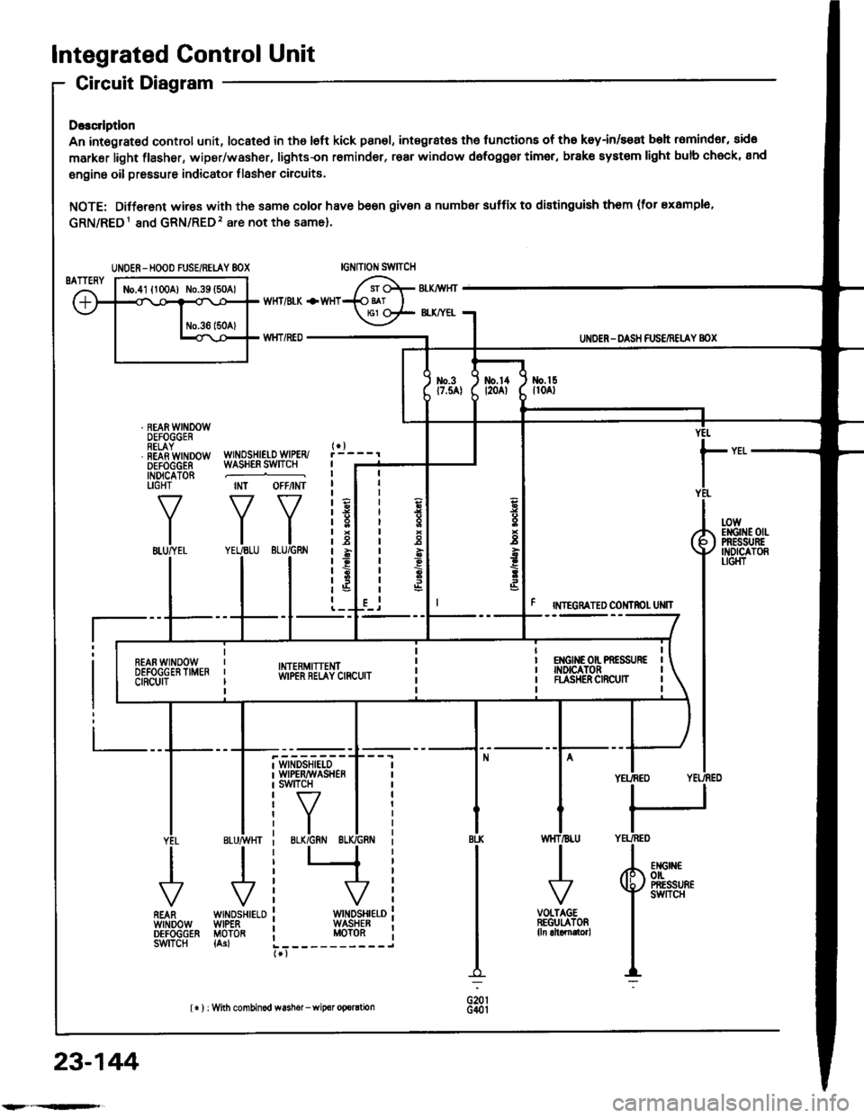
Integrated Control Unit
Circuit Diagram
D.3c ptlon
An integrat€d control unit, located in the left kick panel, integratss the functions of tho keyin/seat beh r6mind€r, sido
markar light {lasher, wiper/washer, lights-on r6minder, rear window dsfogger timer, brak€ system light bulb check, and
enging oil pressure indicator flasher circuitE,
NOTE: Difforent wires with the same color have be6n given a numbor suffix to distinguish them (for Example,
GRN/RED1 and GRN/RED'� are not the same).
WNOSHIELD WIPER/WASHER SWITCH
IMT OFFiINT
I
II
IIIIIIIIIIII
YEUEE
rl
t
P
UNOER - DASH FUS€/RETAY BOX
r NTEGRATED COI{TROI UNIT
t-0wErGrilE 0|lPRESSI'REINDICATORLIGI{T
WINDSHIELOWIPERAVASHERswtTcH
tr-/
IBLK/GRN BI
WINDSHIELOWIPERMOTOR{Asl
VOLTAGEREGULATOR{ln ahamator,
UNOER- HOOD FUSE/RELAY 8OX
I
r3
r8relit;rBt5I
23-144
lr ) : With combinod washef-wip€r oporation
Page 1251 of 1413
Br-u/Brx + fr,rTrtl.* r*r.,
/\JL
r--------Y----__tfl
I moani PosrIoN swtTcH
t,x*rt €- BLK/RE9 -tv-----J
UND€R - OASH FUSE/REI-AY 8OX
ERAKESYSTEMI.IGHTll.4wl
3
a
Et.?
SEAT 8EI-TREMIi/OERLIGHTt1.4Wl
YEI-
RED/BLU
RIGHTFRONTSIDEMASKERI,IGHTt3cP'
| *rt
QiftHl.| (3CP,
IBI..K
{
G30l
I
I
I
a'u, [!
tsl
IBI-K
{
G20rG40l
23-145
Page 1253 of 1413
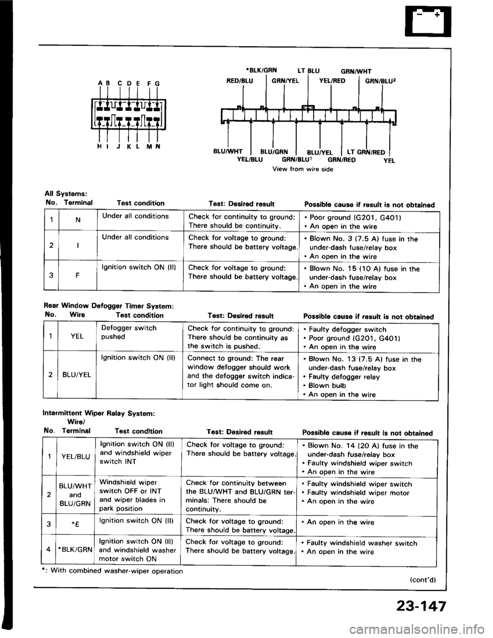
1NUnder all conditionsCheck for continuity to ground:
There should be continuitv.
. Poor ground (G201, G4O1). An open in the wire
Under all conditionsCheck for voltage to ground:
There should be battery voltage.
. Blown No. 3 (7.5 A) fuse in the
under-dash fuse/relay box. An oDen in the wire
F
lgnition switch ON {ll)Check for voltage to ground:
There should be bsttery voltage
. Blown No. 15 (10 A) tuse in the
under-dash fuse/relay box. An open in the wire
All Systems:
No. TsrminalT€st condition
R€ar Window Detogger Timer System:
No. WireTost condition
Intermittent Wip6r Relay System:
Wir€/
No. TerminalTest condition
T6st: Desired rosult
Test: Dosiled result
T€Et: Desir6d result
Possibla cause it result is not obtained
Possible cause il rosult i8 not obtained
Possiblo cause if rosult is not obtained
(cont'd)
IYEL
Defogger switchpushedCheck lor continuity to ground:
There should be continuity asthe switch is Dushed.
Faulty defogger switch
Poor ground {G201, G4O1}
An open in the wire
BLUiYEL
lgnition switch ON (ll)Connect to ground: The rear
window defogger should work
and the detogger switch indica-
tor light should come on.
Blown No. 13 {7.5 Al fuse in the
under-dash fuse/relay box
Faulty defogger relay
Blown bulb
An open in the wire
,|YEL/BLU
lgnition switch ON (ll)
and windshield wipet
switch INT
Check tor voltage to ground:
There should be battery voltage
Bfown No. '14 l2O Al fuse in the
under-dash fuse/relay box
Faulty windshield wiper switch
An oDen in the wire
BLU/WHT
ano
BLUiGRN
Windshield wiper
switch OFF or INT
and wiper blades inpark position
Check for continuity between
the BLUMHT and BLU/GRN ter-minals: There should be
continuity.
Faulty windshield wiper switch
Faultv windshield wiDer motor
An open in the wire
.Elgnition switch ON (lllCheck for voltage to ground:
There should be battery voltage.
. An open in the wire
*BLK/GRNlgnition switch ON (ll)
and windshield washer
motor switch ON
Check for voltage to ground:
There should be battery voltage.
. Faulty windshield washer switch. An open in the wire
*: With combined washer-wiper operation
23-147
Page 1254 of 1413
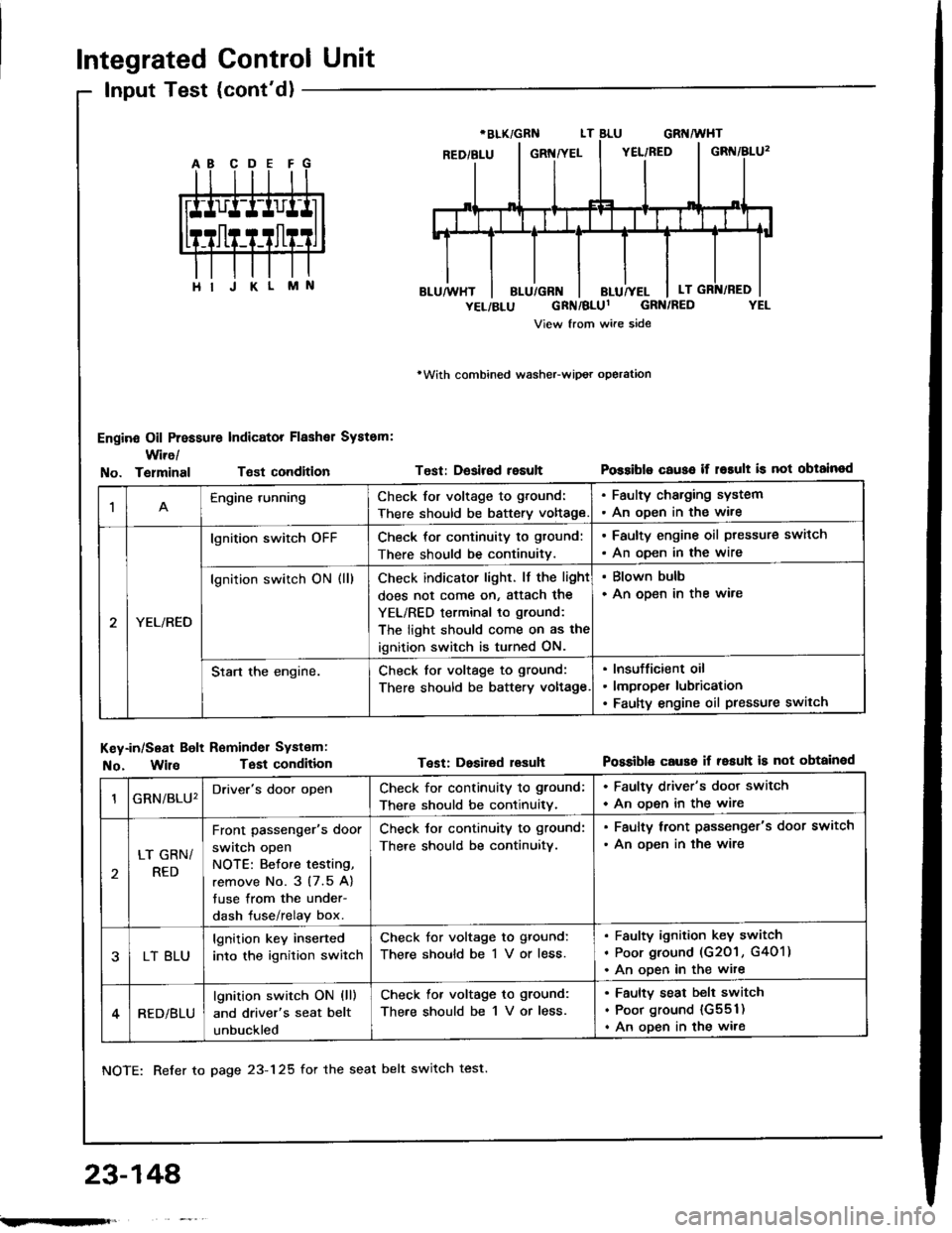
Integrated Control Unit
Input Test (cont'd)
Engine Oil Pressure Indicator Flashal System:
Wire/
rWith combined washeFwipot operation
Test: Desired resultPossiblo c€use if r6rult is not obtainodNo. TelminalTsst condition
M
1Engine runningCheck for voltage to ground:
There should be battery voltage
. Faulty charging system. An oDen in the wire
YEL/RED
lgnition switch oFFCheck for continuity to gtound:
There should be continuitv.
. Faulty engine oil ptessure switch
. An oDen in the wire
lgnition switch ON (ll)Check indicator light. lf the light
does not come on, Sttach the
YEL/RED terminal to ground:
The light should come on as the
ignition switch is turned ON.
. Blown bulb. An open in the ware
Start the engine.Check for voltage to ground:
There should be battery voltage
Insufficient oil
lmproper lubrication
Faulty engine oil pressure switch
Key-in/Seat Bolt Reminder Systam:
No. WilaTest condition
NOTE: Refer to page 23-125 for the seat belt switch test.
Test: Dosired lesuhPossible causo if resuh is not obtainod
23-148'
GRN/BLU'Driver's door openCheck for continuity to ground;
There should be continuitv.
. Faulty driver's door switch
. An ooen in the wire
LT GRN/
RED
Front passenger's door
switch open
NOTE: Betore testing,
remove No. 3 (7.5 A)
tuse from the under-
dash fuse/relay box.
Check tor continuity to ground:
There should be continuitv.
. Faulty lront passenger's door switch
. An ooen in the wire
LT BLU
lgnition key inserted
into the ignition switch
Check for voltage to ground:
There should be 1 V or less.
Faulty ignition key switch
Poor ground (G201 , G401)
An ooen in the wite
RED/BLU
lgnition switch ON (ll)
and driver's seat belt
unbuckled
Check lor voltage to ground:
There should be 1 V or less.
Faulty seat belt switch
Poor ground {G551)
An open in the wire
;.rqFft,