fuel pressure HONDA INTEGRA 1994 4.G Workshop Manual
[x] Cancel search | Manufacturer: HONDA, Model Year: 1994, Model line: INTEGRA, Model: HONDA INTEGRA 1994 4.GPages: 1413, PDF Size: 37.94 MB
Page 24 of 1413
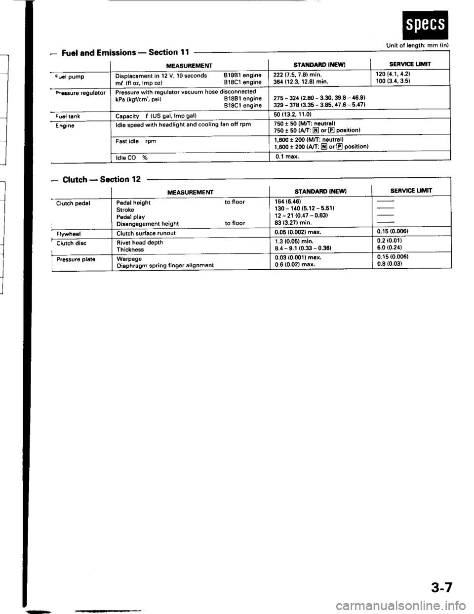
Fuel and EmissionsSection 11
ClutchSection 12
Unit ot length: mm {in)
MEASUREMENTsTAt{ItAno (NewlSERVICE UMIT
.u.l pumpDisolacoment in l2 V, 10 seconds 81881 engine
m, (fl oz, lmp oz) 818C1 engins222 17 .5,7 -81 min. | 12011.1' 1'21
364 (12.3, 12.8) min. I too (:.1, g.st
F aa3uro rggulatorPressure with regulator vacuum hose disconnected
kPa (kgflcm', psi) Bl8Bl engineBl8Cl engin€275 - 32a 12.8 -3.9,39.6 - 46.9)329 - 378 (3.35 - 3.85, 47.6- 5.47)
tualt6nkCaprcity, {US gal, lmp gal)50 (13.2, 11.01
En9in6ldle sDeed with headlight and cooling fan ofi rpm7501 50 (M/T: neut..ll750I 50 {A/T: E or E position}
Fast idle rpm1,600 i 2(x' lM/T: nsurr6l)l,eoo I 200 (A/T: E or E po6itioo)
ldl6 CO %0.1 max.
MEASUREMENTSTAM'Ad' IiEWISERVICE UMIT
clutch padslP6d6l height to lloor
SirokePedal play
Disengagement height to floor
164 (6.46)
130 - 140 (5.12 - 5.51)12 - 21 (0.47 - 0.83)83 (3.27) min.
Clutch sudace runout0.05 10.002) max,0.'15 (0.006t
clutch discRiv€t h€ad depthThickness
1.3 (0.05) min.8.4- 9.1 (0.3 - 0.36)0.2 (0.011
6.0 (0.24)
Pr6sur6 plat€WarpageOiaphragm spring linger alignment0.03 (0.001) mrx.0-6 (0.02) ma*0.15 (0.006)
0.8 (0.03)
{n+
3-7
Page 49 of 1413
Engine Removal/lnstallation
m
(cont'd)
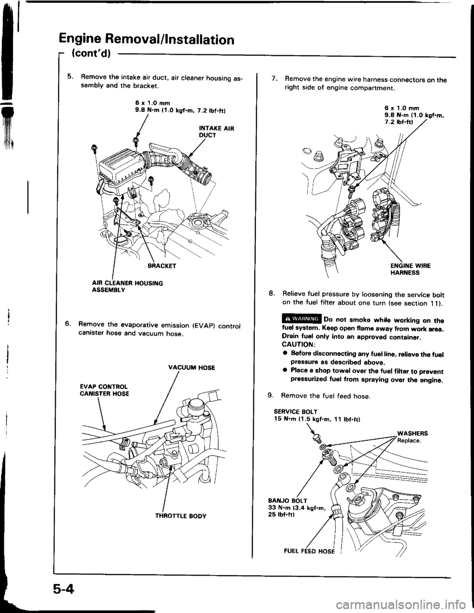
Remove the intake air duct, air cleaner housing as-semblv and the bracket.
6 x 1.O mm9.4 N.m {l.O ksf.m, 7.2 tbf,ftl
Remove the evaporative emission (EVAp) controlcanister hose and vacuum hose.
VACUUM HOSE
THROTTI.E BODY
7. Remove the engine wire harness connectoE on theright side of engine compartment.
8. Relieve fuel pressure by loosening the service bolton the tuel filter about one turn {see section 1 1).
@ oo not amoke whito working on thofuel system. Keep open flame away trom wo.k arsa.Drain fuel only into an approved container.CAUTION:
a Before disconnocting any fu€l line. reliovo the tuolpressule as doscribed above.a Place a shop towel ov61 the fu6l filter to prevontprossurized tuel from spraying ovel tho aogine.
9. Remove the fuel feed hose.
SERVICE BOLT15 N.m (1.5 kgt.m, 11 tbt.ftl
BAITJO EOLT33 N.m 13.4 kgt.m,25 tbt.ftt
6 x'l.O mm9.8 N-m ll.0 kgt.m.
Page 78 of 1413
Gylinder Head
Removal
I
t
Engine removal is not required for this procedure.
CAUTION: To avoid damaging tho cylinder head, wait
until tho ongino coolant temporature drops bolow 100"F
{38"C) beforo loo36ning the rotainin0 bolts.
NOTE:
. Inspect the timing belt before removing the cylinder
neao.
. Turn the crankshaft pulley so that the No. 1 piston is
at top dead center (TDCI (page 6-12).
. Mark all emissions hoses before disconnecting them.. Anti-theft radios have a coded theft protection circuit.
Be sure to get the customer's code number before.- Disconnecting the battery.- Removing the No. 32 (7.5 A) fuse irom the under-
hood fuse/relay box.- Removing the radio.
After service, reconnect oower to the radio and turn it
on.
When the word "CODE" is displayed, enter the cus-
tomer's 5-digit code to restore radio operation.
1. Disconnect the negative terminalfrom the battery.
2. Drain the engine coolant (see page 10-5).
. Remove the radiator cap to speed draining.
3. Relieve fuel pressure (see Section 1 1).
@ Do not smoke whils working on tusl
systom, keep opon flame or spark away trom work
area. Drain fuol only inlo an approvod containsr.
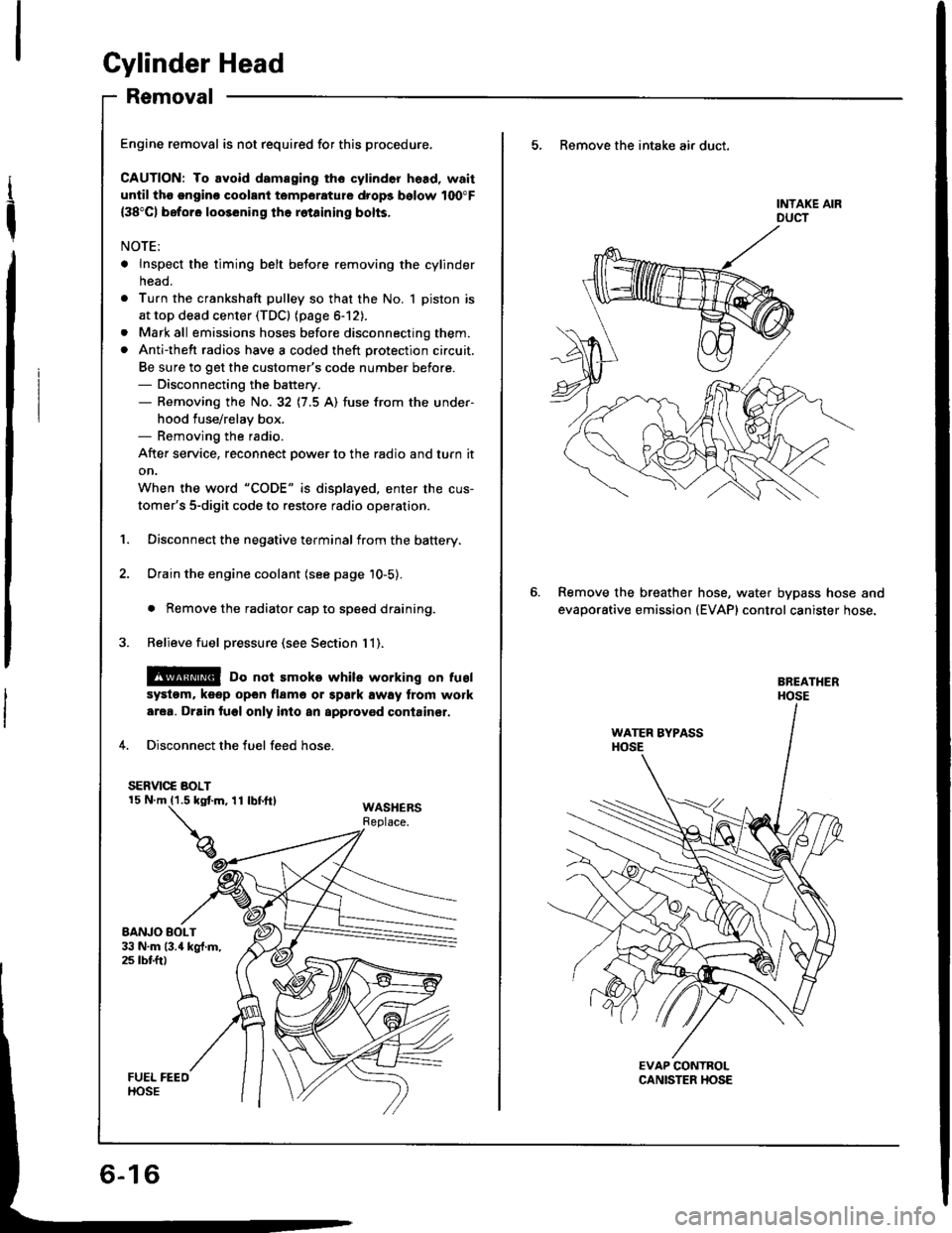
4. Disconnect the fuel feed hose.
SERVIC€ BOLT
WASHERSReplace.
5, Remove the intake air duct.
Remove the breather
evaporative emission
hose, water bypass hose and(EVAP) control canister hose.
Page 116 of 1413
Cylinder Head
Removal
Engine removal is not required or this procedure.
CAUTION: To avoid damaging tho cylinder head, wail
u[tilths.nginc coolant tsmperaturo drops bolow 100"F(38'Cl bafore loos6ning tho retaining bolts.
NOTE;
. Inspect the timing belt before removing the cylinder
head.
Turn the crankshaft pulley so that the No. 1 piston is
at top dead center (TDc) {page 6-51).
Mark all emissions hoses betore disconnecting them.
Anti-theft radios have a coded theft protection circuit.
Be sure to get the customer's code number before- Disconnecting the battery.- Removing the No.32 (7.5 A) fuse trom the under-
hood fuse/relay box.- Removing the radio.
After service, reconnect power to the radio 8nd turn it
on.
When the word "CODE" is displaved. enter the cus-
tomer's 5-digit code to restore radio operation,
Disconnect the negative terminal from the battery.
Drain the engine coolant (see page 10-5).
. Remove the radiator cap to speed draining.
Relieve fuel pressure (see section 111.
l@ Do not 3moke whilo working on fuel
a
a
'1.
systgm. ko6p opon tlamo ot Spark away trom work
aroa. Drain fugl only into an approved containsr,
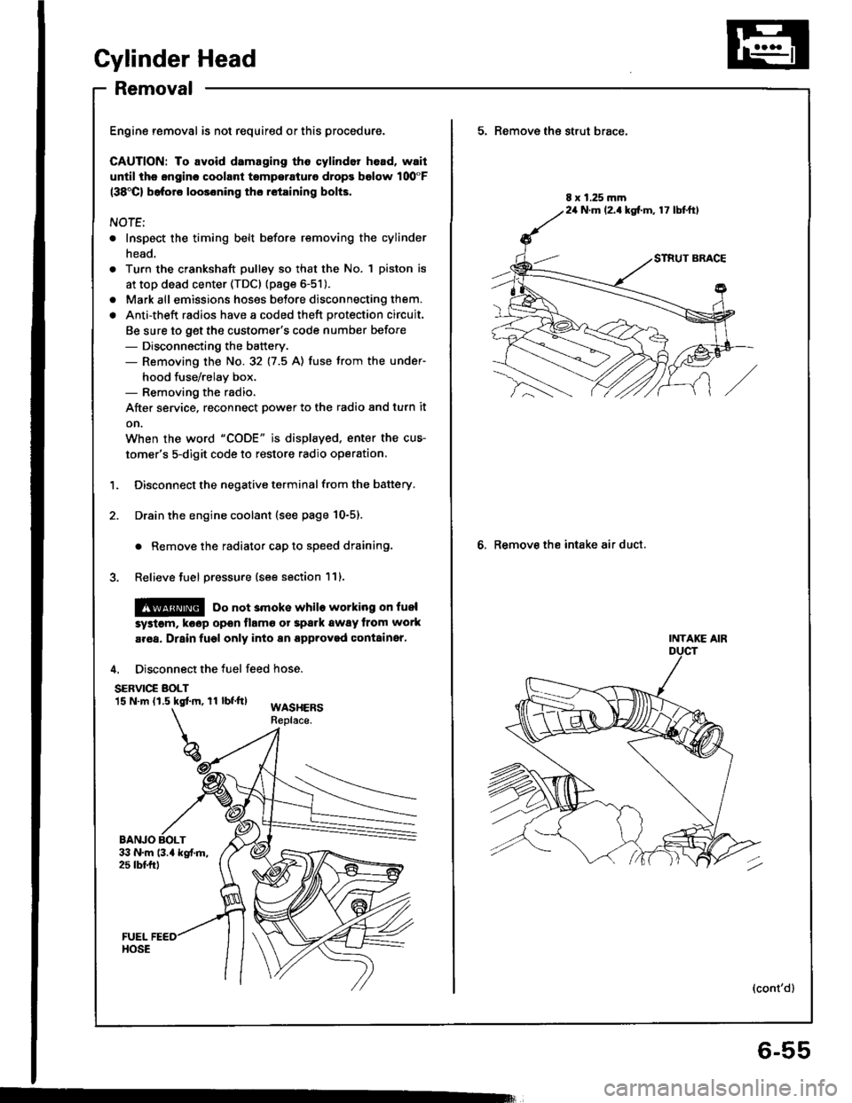
4. Disconnect the fuel feed hose.
SERVIC€ BOLT15 N.m (1.5 kgtm, rl bf.tt)WASHERSReplace.
BANJO BOLT
5. Remove th€ strut brace,
6. Remove the intake air duct.
8 x 1.25 mm24 N.m (2.1kg[.m, 17 lbtftl
INTAKE AIR
(cont'd)
6-55
Page 118 of 1413
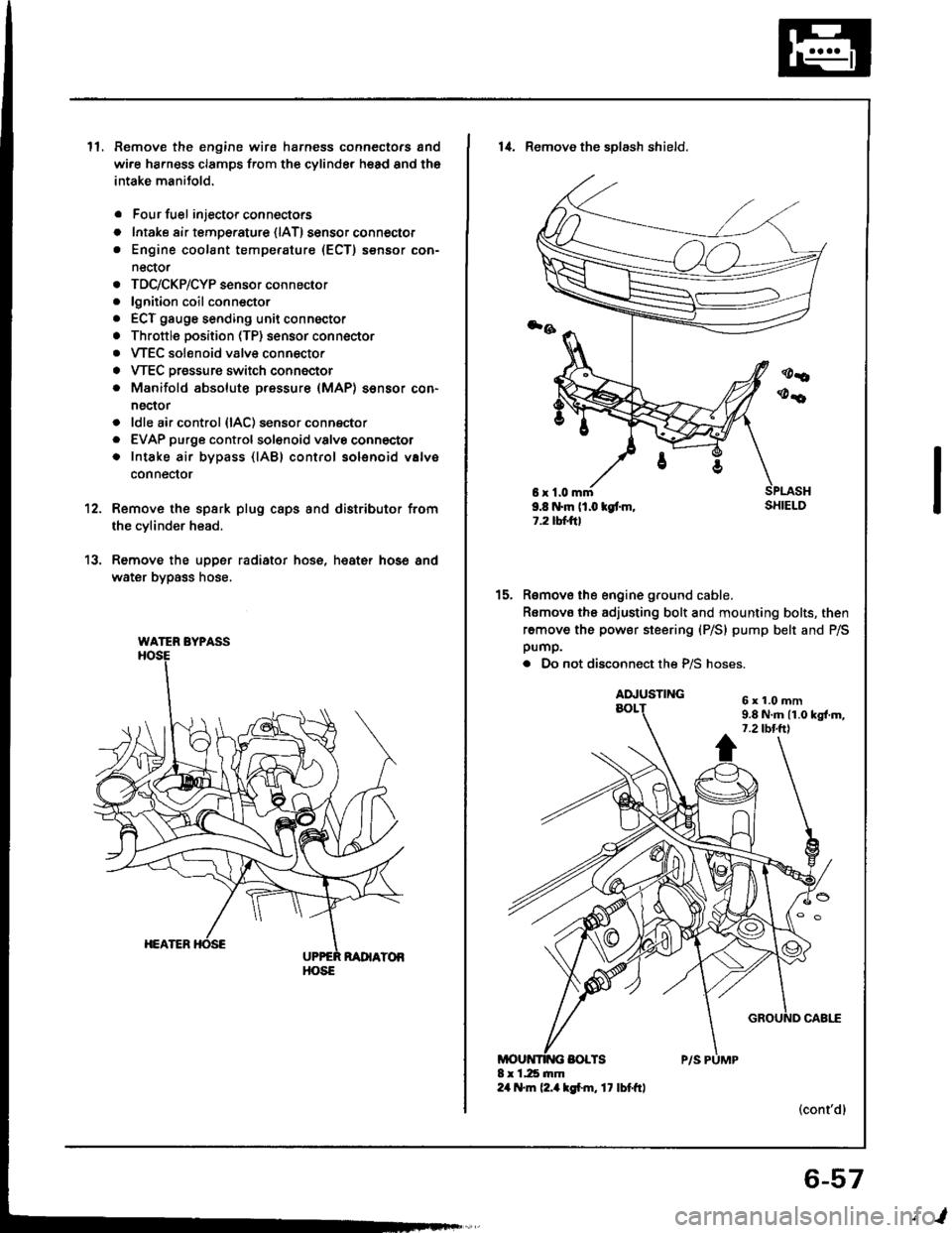
ll.Remove the engine wire harness connectors and
wi.e ha.ness clamps from the cylinder head and the
intake manitold.
Four fuel injector connectors
Intake air tempe.ature {lAT) sensor connector
Engine coolant temperature (ECT) sensor con-
nector
TDC/CKP/CYP sensor connector
lgnition coil conn€ctor
ECT gauge sending unit connector
Throttle position (TP) sensor connector
VTEC solenoid valve connector
VTEC Dressure switch connector
Manifold absolute pressure (MAP) sensor con-
nector
ldle air control {lAC) sensor connector
EVAP purge controlsol€noid valvo connector
Intake air bypass {lABl control solenoid valve
conneclor
a
o
a
o
a
a
a
a
a
a
a
a
a
12.
13.
Remove the spsrk plug caps and distributor from
the cylinder head.
Remove the upper radiator hose, heat€r hose and
water bypass hose.
WATER BYPASS
HOSE
6r1.0mm9.8 N.m (1.0 kgt m,1.2 tbtftl
14. Remove the sDlash shield.
Remove the engine ground cable.
Romovo the adjusting bolt and mounting bolts, then
remove the power steering (P/S) pump belt and P/Spump.
. Do not disconnect the P/S hoses.
(cont'dl
15.
6x1.0mm9.8 N.m 11.0 kgl.m,7.2 tbt.ttl
6-57
,l
Page 194 of 1413
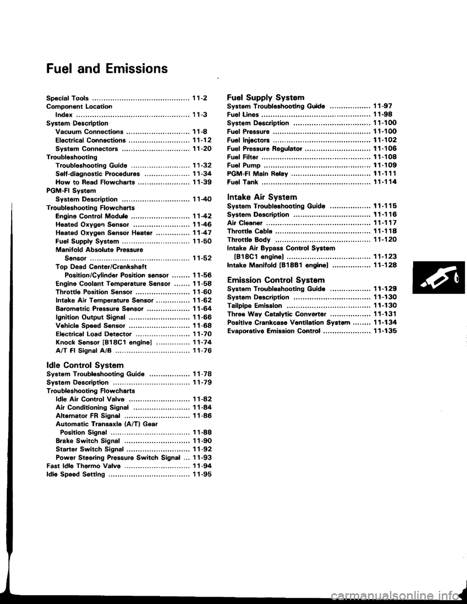
Fuel and Emissions
Spocial Tools ................ 1 1-2
Compon€nt Location
lndex ................. ...... 11-3
System Description
Vacuum Connectiona .......,.................... 1 1 -8
Efectrical Connections ....,.,.,......,...,,.....,'11-12
Syst€m Connectors ...,...,.................-.--. 11-2O
T.oubloshooting
Troubleshooting Guido .......................... 1 1-32
Self -diagnostic Procedures .,..,............... 1 1 -34
How to Road Flowcharts ...................,... 11-39
PGM-Fl System
Systom Description .............................. 1 l-4O
Troubleshooting Flowcharts
Engine Control Moduls ............... ........... 1 1 -42
Heated Oxygon Sensor ......,.................. 1 1-46
Heated Oxyg€n Sonsol Heatel .....,......... 1 1 -47
Fuel Supply System ..............-............... 1 1-50
Manitold Absolute Pressure
Ssnsor ............................................ 1 1-52
Top D6ad Cente./Crankshatr
Position/Cylindor Position sonsor ........ 1 1 -56
Engine Coolant Tempsrature Sonsor ....... 11-58
Throttlo Position Sonsor ........,..,,........... 1 1-60
Intake Air Temperaturs Sensor ............... 11-62
Baromet c Prsssuro Sensor ......,...,...,..,. 11-64
lgnition Output Signal ........................... 1 1 -66
Vehicle Spe€d Sensor ........................... 1 1 -68
Electdcal Load Dotector ....,...,..........,.... 1 1 -7O
Knock Sensor [818C1 engine] ............... 11-74
A/T Fl Signal A/B ................................. 1 1-76
ldle Contlol System
System Troubleshooting Guide .................. 1 1 -78
Systom Description ........ 11-79
Troubloshooting Flowchans
ldl€ Ail Control Valve ........................... 1 1 -82
Ail Conditioning Signal ......................... 1 1 -84
Altemator FR Signal ............................. 1 1 -86
Automatic Transaxle (A/T) Gear
Position Signal ......... 11-88
Brake Switch Signal ............................. 1 1 -9O
Startel Switch Signal ............................ 11-92
Power Steering Pressure Switch Signal ... 11-93
Fast ldle Thermo Valve ...................,......... 1 1 -94
ldls Speed S€tting .................................... 1 1 -95
Fuel Supply System
Systam Tloubloshooting Guid. .................. 1 1 -97
Fuol Linos ...................... 1'l -98
System Description ........ 11-100
Fuol Prassure ................. 11-100
Fu6l Ini6ctors ................. 11-102
Fuel Pressure Ragulato. .,. 11-106
Fuel Filter ...................... 11-108
Fual Pump ..................... 11-109
PGM-Fl Main F6lay ................................... 1 1"1 1 1
Fuel Tank ...................... t 1-114
Intake Air System
System Troubloshooting Guido .................. 1 1 -1 1 5
Systom Dascription ........ 11-116
Air Clean€r .................... 11-117
Throttls Cable ................'11-118
Throttl8 Body ................ 11-120
lntake Air Bypass Cont.ol Systsm
[B18Cl enginal .,......... 11-123
Intake Manilold [B1881 onginol ................. 11-128
Emission Control System
Systsm Troubleshooting Guido .................. 1 1 -1 29
Systam Doscription ........ 11-130
Tailpips Emission ........... 11-130
Thrae Way Catalytic Convortor ...,...,........., 11-131
Positiva CrankcaEo V6ntilation Systcm .,....., 11-134
Evaporativo Emission Contro|,..,..,.,.,,.,,..,.., 1 1-135
Page 195 of 1413
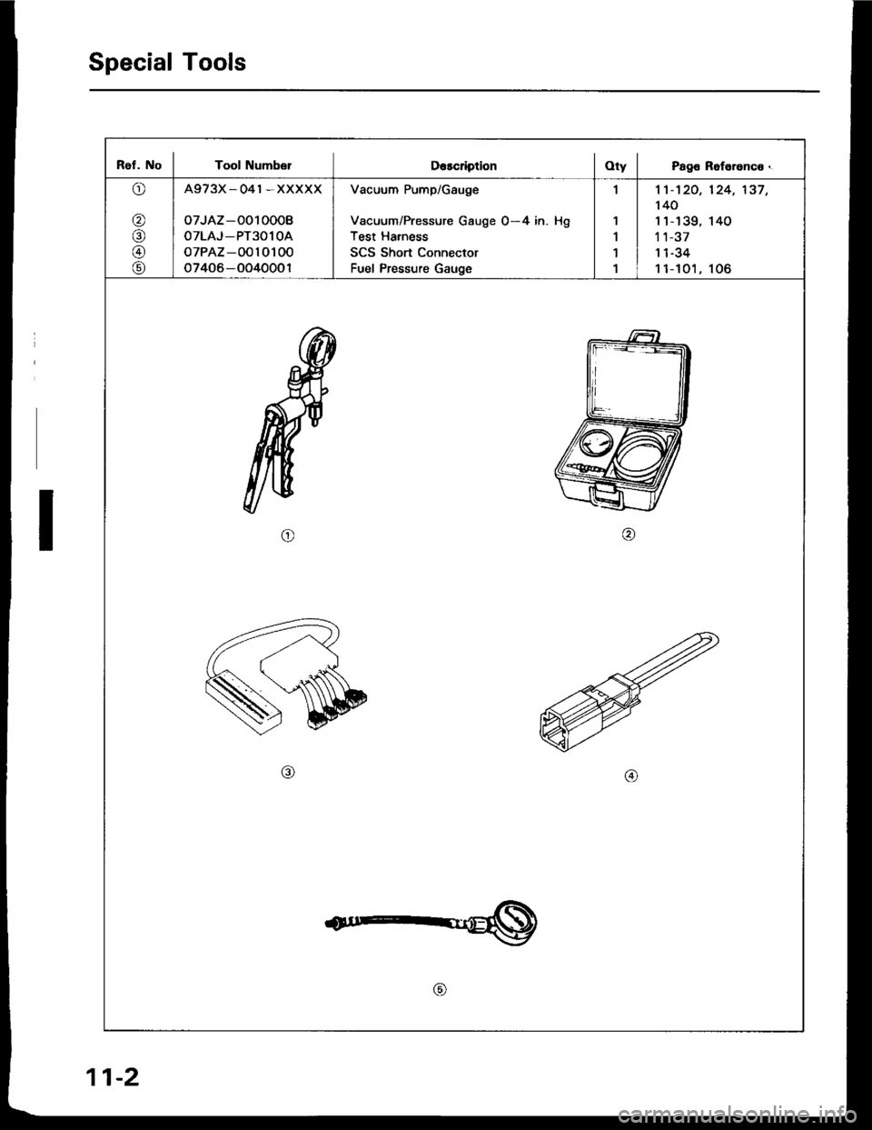
Special Tools
Ref. No I Tool Numb€rDescription I OtV I Page Reference.
o
@
@
@
@
A973X_041*XXXXX
oTJAZ -O010008
OTLAJ_PT3O1OA
oTPAZ-0010100
o7406-OO40001
Vacuum Pump/Gauge
Vacuum/Pressure Gauge 0-4 in. Hg
Test Harness
SCS Short Connector
Fuel Pressure Gauge
,l
1
1'l
1
1't -'t 20,
140
11-139,'t 1-37
I t -J.+
11-t01,
124,'137,
140
106
o
11-2
Page 201 of 1413
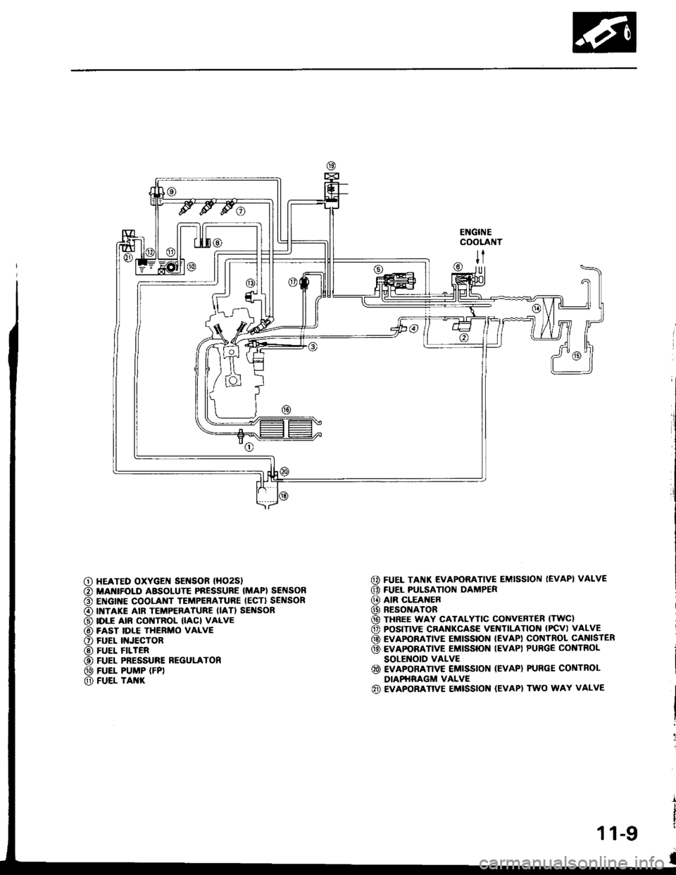
ENGINECOOLANT
@ FUEL TAI{K EVAPORATIVE EMISSION (EVAP} VALVE
G) FUEL PULSATION DAMPER
@ AIR CLEANER
@) RESONATOR
@ THREE WAY CATALYTIC CONVEnTER (TWC)
o POS|TIVE CRANKCASE VEITITILAT|ON IPCV) VALVE
@ EVAPOBATIVE EMISSION IEVAP) COI{TROL CANISIER
@ EvApoRATrvE EMrssroN IEVAP) PURGE coNTRoL
SOLENOID VALVE
@ EVAPORATTVE EMISSION (EVAP) PURGE CONTROL
DIAPHRAGM VALVE(iD EVAPORATIVE EMISSION (EVAPI TWO WAY VALVE
|l
U]
HEATED OXYGEI{ SEI{SOF (HO2S}
MANIFOI.D ABSOLUTE PRESSURE (MAP) SEI{SONENGINE COOLANT TEMPERATURE IECT} SENSORINTAKE AIR TEMPERATURE IIAT} SEI'ISORIDLE AIR CONTROL IIAC) VALVEFAST IDLE THERMO VALVEFUEL II{JECTORFUEL FILTERFUEL PRESSURE REGULATONFUEL PUMP IFP)FUEL TAI{K
11-9
Page 203 of 1413
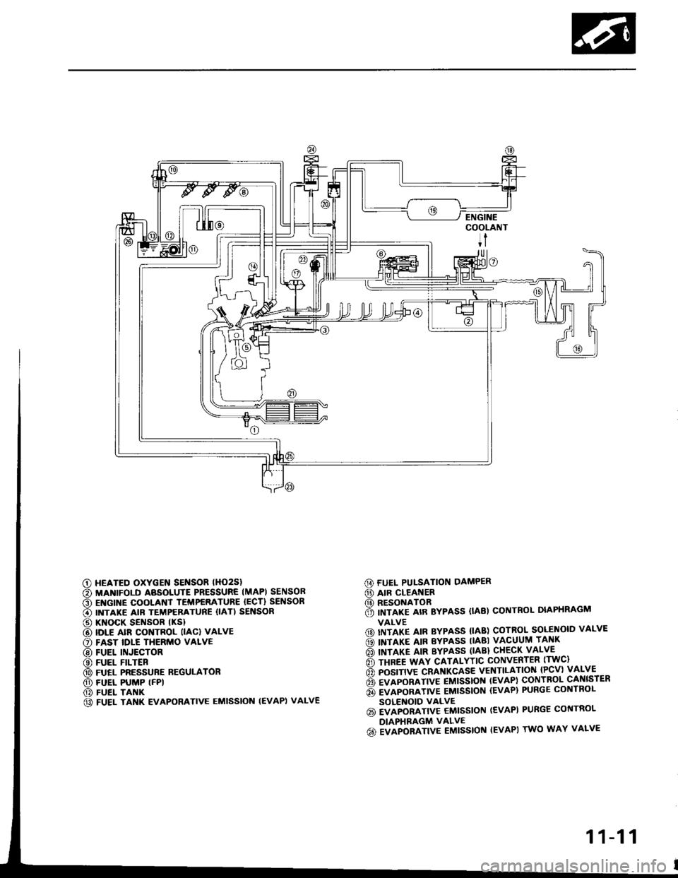
G) FUEL PUI-SATION DAMPER
@ AIR CLEANER(D RESONATOR6 imrlre arR Bypass (tAB) coNTRoL DIAPHRAGM
VALVE(D) IITITP IIN BYPASS {IAB) COTROL SOLENOID VALVE
ds) INTIXT AIR EYPASS TIABI VACUUM TANK
rio'l rnrarg ltn BYPASS (lABl cHEcK vALvE
6 rsnee wav cATALYTtc coNvERTER lrwc)
6 posrnve cRAf{KcAsE vENTILATIoN {Pcv) vALVE
6 evlponlrtve EMtsstot{ tEvAPl coNTBoL cANlsrER
6 evlponltvE EMtssloN {EvAP} PURGE coNTRoL
SOLENOID VALVE6i EVAPORATIV€ EMISSION (EVAPI PURGE CONTROL
DIAPHRAGM VALVE
6o ivlpoalrtve Eutsstof{ IEVAPI rwo wAY vALvE
c) HEATED OXYGEN SENSOR lHO2Sl
€) MANIFOLD ABSOLUTE PRESSURE IMAPI SENSOB
O EI{GINE COOLANT TEMPERATURE {ECT} SENSOR
€) INTAKE AIR TEMPERATURE {IAT) SENSOR
@ KNOCK SENSOR tKSl
@ IDLE alR coNTRoL llAcl vALvE
O FAST IDLE THERMO VALVE
@ FUEL INJECTOR
@ FUEL FILTER
@ FUEL PRESSURE REGULATOR
O) FUEL PUMP (FPI
@) FUEL TANK
@ FUEL TANK EVAPORATIVE EMISSION IEVAPI VALVE
11-11
Page 228 of 1413
Troubleshooting
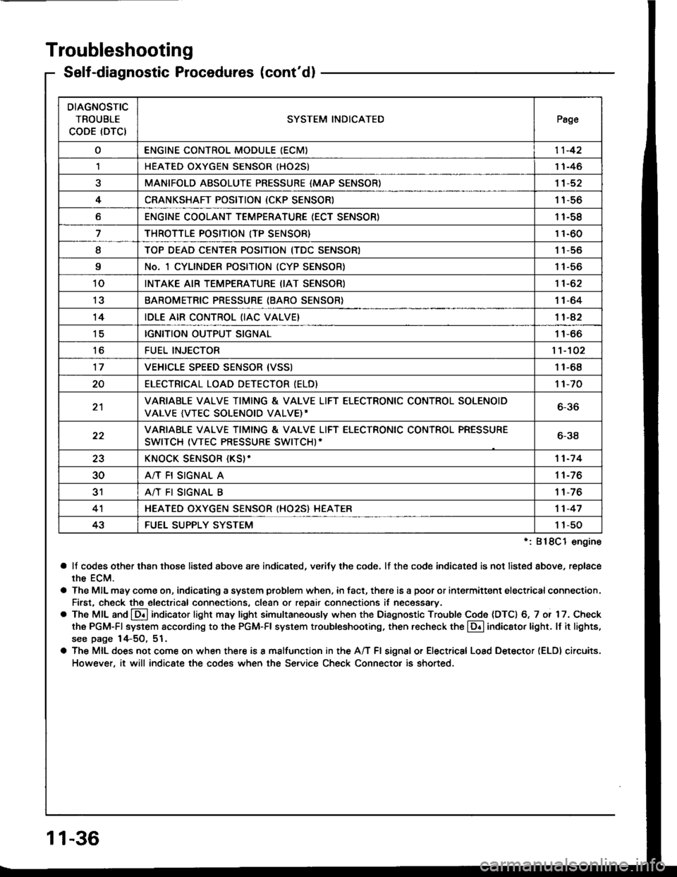
Self-diagnostic Procedures (cont'dl
':818C1 engine
a lf codes other than those listed above are indicated, verifv the code. lf the code indicated is not listed above, replace
rhe ECM.
a The MIL may come on, indicating a system problem when, in fact, there is a poor or intermittent electricalconnection.
First, check the electrical connections, clean or repair connections it necessary.
o The MIL and @ indicator light may light simultaneously when the Diagnostic Trouble Code (DTC) 6, 7 or 17. Check
the PGM-Fl system according to the PGM-Fl system troubleshooting, then recheck the l!! indicator light. ll it lights,
see page 14-5O, 51.
a The MIL does not come on when there is a malfunction in the A/T Fl signal or Electrical Load Detector (ELDI circuits.
However, it will indicate the codes when the Service Check Connector is shorted.
DIAGNOSTIC
TROUBLE
CODE (DTCISYSTEM INDICATEDPsge
oENGINE CONTROL MODULE IECM)11-42
,lHEATED OXYGEN SENSOR IHO25)1 1-46
aMANIFOLD ABSOLUTE PRESSURE {MAP SENSOR)11-52
4CRANKSHAFT POSITION (CKP SENSOR)1 1-56
oENGINE COOLANT TEMPERATURE (ECT SENSOR)11-58
THROTTLE POSITION (TP SENSOR}11-60
ITOP DEAD CENTER POSITION (TDC SENSORI1 1-56
9No. 1 CYLINDER POSITION (CYP SENSOR)1 1-56
10INTAKE AIR TEMPERATURE (IAT SENSOR)11-62
13BAROMETRIC PRESSURE (BARO SENSOR}1|-64
14IDLE AIR CONTROL (IAC VALVE}11-42
tcIGNITION OUTPUT SIGNAL11-66
toFUEL INJECTOR1't-102
17VEHICLE SPEED SENSOR {VSSI11-68
20ELECTRICAT LOAD DETECTOR (ELD)'t 1-70
21VARIABLE VALVE TIMING & VALVE LIFT ELECTRONIC CONTROL SOLENOID
VALVE {VTEC SOLENOID VALVE)'6-36
22VARIABLE VALVE TIMING & VALVE LIFT ELECTRONIC CONTROL PRESSURE
SWITCH (VTEC PRESSURE SWITCHI-6-38
23KNOCK SENSOR {KS}-11-7 4
30A/T FI SIGNAL A11-76
3'rA/T FI SIGNAL B1 1-76
4'lHEATED OXYGEN SENSOR (HO25} HEATER11-47
43FUEL SUPPLY SYSTEM1 1-50
11-36