ac circuit HONDA INTEGRA 1994 4.G Workshop Manual
[x] Cancel search | Manufacturer: HONDA, Model Year: 1994, Model line: INTEGRA, Model: HONDA INTEGRA 1994 4.GPages: 1413, PDF Size: 37.94 MB
Page 1396 of 1413
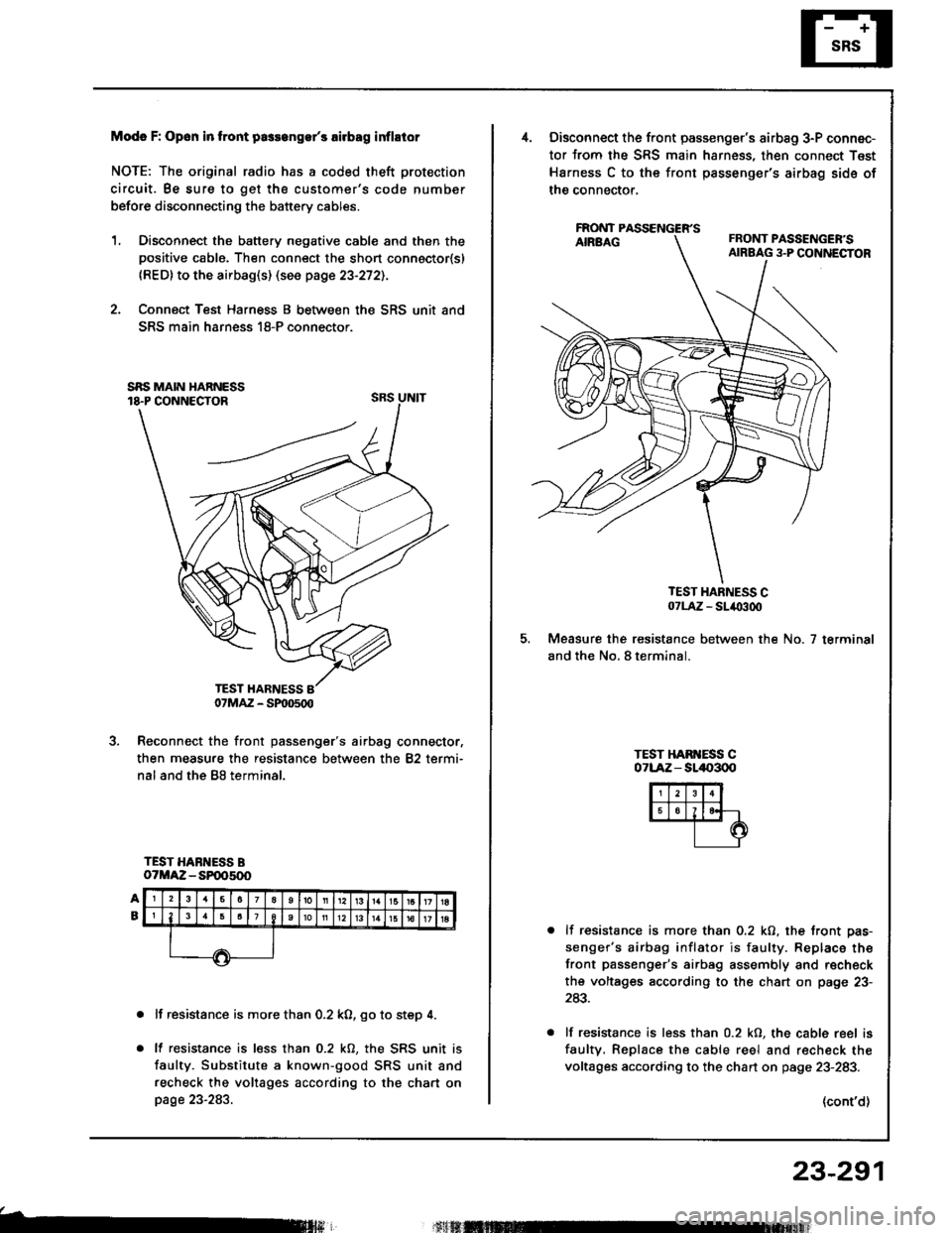
Modc F: Opon in tront pa3s6ngs/s rirbag inflstor
NOTE: The original radio has a coded theft protection
circuit. Be sure to get the customer's code number
before disconnecting the battery cables.
1, Disconnect the battery negative cable and then thepositive cable. Then connect the short connoctor{sl
{RED} to the airbag(s) (see page 23-272).
2. Connect Test Harness B between the SRS unit and
SRS main harness 18-P connector.
SRS UNIT
Reconnect the front passenger's airbag connector,
then measure the resistance between the 82 termi-
nal and the B8 terminal.
TEST HARNESS BoTMAZ - SP005(x)
lf resistance is more than 0.2 k0, go to step 4.
lf resistance is less than 0.2 kO, the SRS unit is
faulty. Substitute a known-good SRS unit and
recheck the voltages according to the chart onpage 23-283.
b
07MAZ - SP|D500
Disconnect the front passenger's airbag 3-P connec-
tor from the SRS main harness, then connect Test
Harness C to the front passenger's airbag sids of
the connector,
FAONT
TEST HARNESS C07LA,Z - SL/O300
Measure the resistance between the No. 7 terminal
and the No. 8 terminal.
TEST HAB ESS C071-Aiz - sll|{,300
lf resistance is more than 0.2 kO, the front pas-
senger's airbag inflator is faulty. Replace the
front passenger's airbag assembly and r€check
the voltages according to the chart on page 23-
243.
lf resistance is less than 0.2 kO, the cable reel is
faultv. Replace the cable reel and r€check the
voltages according to the chart on page 23-283.
(cont'd)
23-291
Page 1397 of 1413
Supplemental Restraint System (SRSI
Troubleshooting {cont'dl
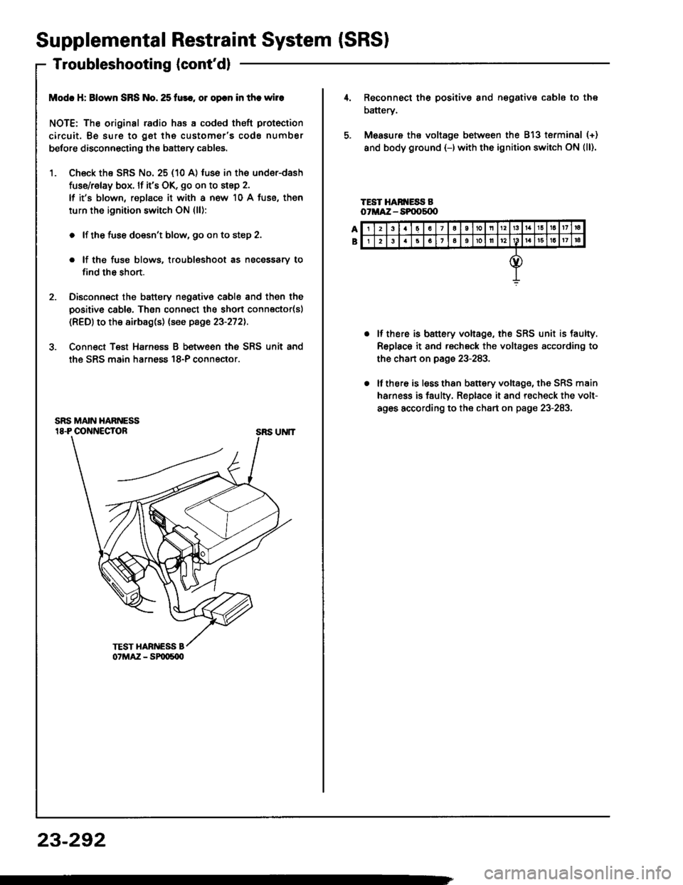
Modc H: Blown SRS No. 25 fur., ol opcn in the wire
NOTE: The original radio has a coded theft protection
circuit. Be sure to get the customer's code number
betore disconnecting the battery cables.
1. Ch€ck the SRS No. 25 (10 A) fuse in the under-dash
fuse/relay box. lf it's OK, go on to step 2.
lf it's blown, replace it with a now 10 A fuse, then
turn the ignition switch ON (ll):
. lf the fuse doesn't blow, 90 on to step 2.
. lf the fuse blows. troublsshoot as necessary to
find th6 short.
2. Disconnect the battery negative cable and then the
positive cable. Then connect the short connector(sl
(RED) to the airbag(s) (see page 23-272).
3. Conn€ct Teat Harnsss B between the SRS unit and
the SRS main harness 18-P connector.
SRS UNIT
23-292
23a7a10nl3161a17ra
26161oll12161a17|a
Reconnect th6 positiv€ 8nd negative cable to the
battery.
Measure ths voltage between the 813 terminal (+)
and body ground {-)with the ignition switch ON (ll).
TEST HAN ESS BoTMA:Z - SPOOs{X'
lf there is battery voltage, the SRS unit is faulty.
Replace it and rscheck the voltages according to
the chan on page 23-283.
lf there is lsss than b8ttery voltage, the SRS main
harness is faulty. Replace it and recheck the volt-
ag6s according to the chart on page 23-283.
Page 1398 of 1413
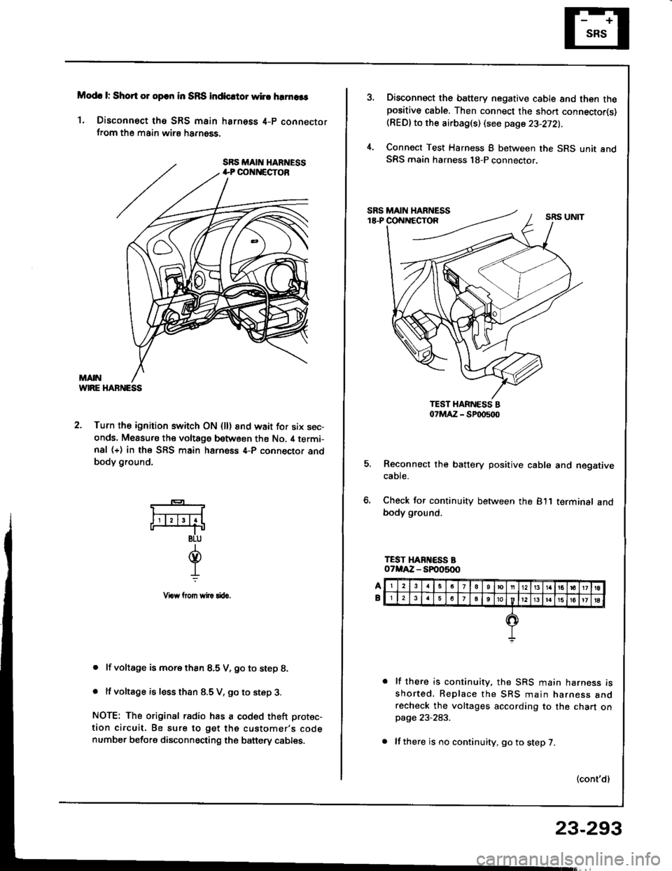
Modc l: Short 01 opcn in SRS indicrtor whc hrrnaas
1. Disconnect tho SRS main harness 4-p connectorfrom the main wirs harn6ss.
WIRE HABNESS
2. Turn the ignition switch ON (ll) 8nd wait for six sec-onds. Measu.s the voltage between ths No. il termi-nal (+) in the SFS main harness 4-P connector andbody ground,
. lf voltage is more thsn 8.5 V, go to step 8.
. It voltage is less than 8.5 V, go to step 3.
NOTE: The original radio has a coded theft protec-
tion circuit. Be sure to get the customer's codenumber before disconnecting the banery cables.
*-
F4
BLU
d.L
Vrow llom wi|! rftro.
Disconnect the battery negative cable and then thepositive cable. Then connect the sho.t connector(s)(REDlto the airbag(s) (see page 23-272).
Connect Test Harness B between the SRS unit andSRS main harness 18-P connector.
5. Reconnect the battery positive cable and negativecaote.
6, Check for continuity between the 811 terminalbody ground.
lf there is continuity, the SRS main harness isshorted. Replace the SBS main narness anorecheck the voltages according to the chart onpage 23-283.
lf there is no continuity, go to step 7.
(cont'dl
23-293
Page 1399 of 1413
Supplemental
Troubleshooting(cont'dl
RestraintSystem (SRSI
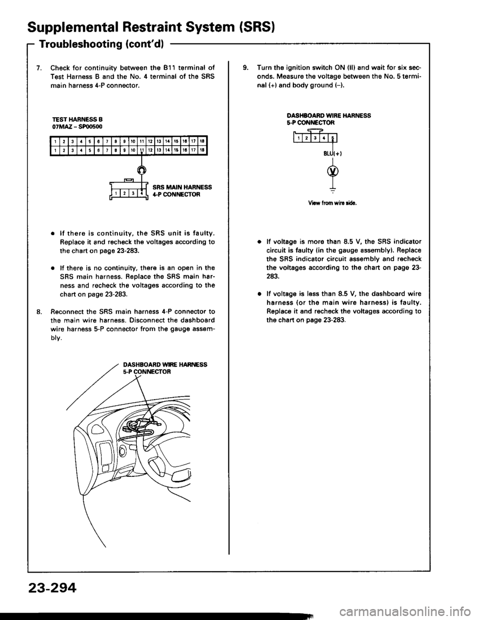
7.Check for continuity between the 811 terminal of
Test Harness B and the No. 4 terminal of the SRS
main harness 4-P conngctor,
oTurn ths ignition switch ON {ll} and wait for six sec-
onds. Measure the voltage between the No. 5 termi-
nal (+) and body ground (-).
TEST HARNESS B07MAZ - SF|D500
OASHSOARO IVIRE HARNESSs.PCO ECTOR
Vraw from sil! rira,
8.
. lf there is continuity, the SRS unit is faulty,
Replace it and recheck the voltages according to
the chart on page 23-283.
. lf there is no cootinuity. there is an open in the
SRS main harness. Replace the SRS main h8r-
ness and recheck the voltages according to the
chart on page 23-283.
Reconnect the SRS main harness 4-P connecto. to
the main wire ha.ness. Disconnect the dashboard
wire ha.ness 5-P connector from the gauge assem-
Dtv.
lf voltage is mora than 8.5 V, the SRS indicator
circuit is faulty (in the gauge assemblyl. Replace
the SRS indicator circuit assembly and recheck
the voltsges according to the chart on page 23-
243.
lf voltage is less than 8.5 V, the dashboard wire
harness (or th€ main wire harness) is faulty.
Replace it and recheck the voltages according to
the chart on page 23-283.
DASHBOARD WIRE HARNESS5.P OONNECTOR
23-294
Page 1400 of 1413
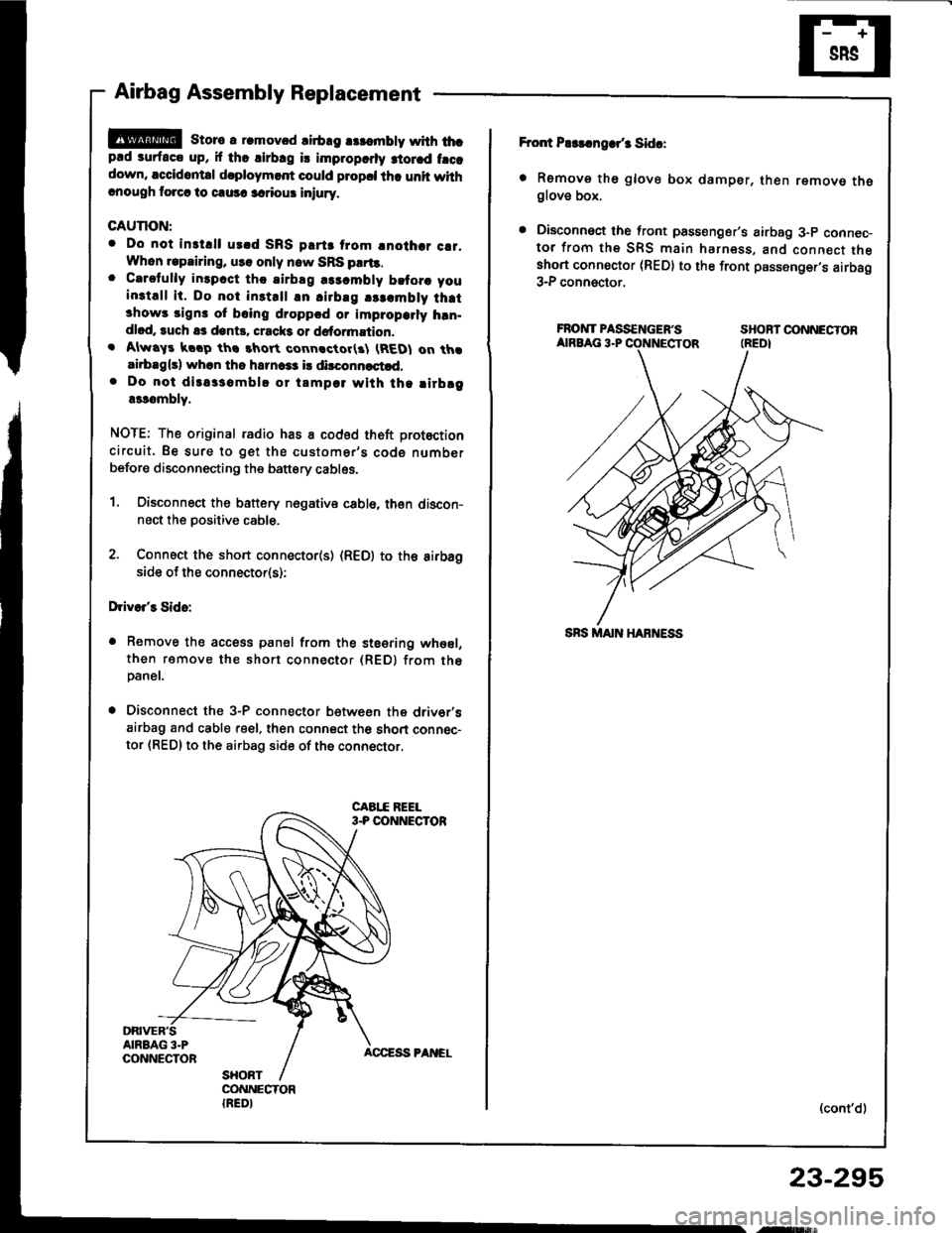
Airbag Assembly Replacement
@E storc a r.movcd lirb.g rslombty with thcp.d surfaco up, if tho lirbrg is improparly 3iorad frcadown, accidontal d.ploymert could plopcl tha unit withcnough torcr lo causc lariour iniury.
CAUTION:
. Do not inst.ll urld SRS plrts trom lnothar c!1,Whon lepairing, uss only now SRS prrt!.o Carefully inlpcct thc airblg rlrcmbly bltorc you
install it. Do not inst.ll an airbag !$.mbly thrt3how! sign3 of bcing droppcd or improparly hrn-dlod, such as dont!. crack3 or dstormation.. Alwry! koop ths rhort connactor(3l (REDI on thaairbrg{s} whon tho hsrnca3 i! dirconnastld.. Do not diras3ombl! or tamp€l with tha lirbrga$ombly.
NOTE: The original radio has a coded th6ft protection
circuit. Be sure to get the customer's code number
before disconnecting the battery cables.
1. Oisconnect the battery nogative cabl6, then discon-nect the positive cable.
2. Connect the short connecto(s) (R€D) to the aifbagside of the connector(s);
Drivo/s Sido:
a Remove the access panel from the steering whesl,
then ramove the short connector (REDI from th6paner.
. Disconnect the 3-P connector betwesn the driv6r'sairbag and cable reel, then connect th6 short connec-
tor {RED} to the airbag side of the connector.
Fror{ P$!.ngar/3 Sida:
. Remove th6 glove box damper, then remove theglove box.
. Disconnoct the front psssenger's airbag 3-p connec-tor from the SRS main harness, and connect theshort connoctor (RED) to the front passenger,s airbag3-P connector.
FROIVTPASS€NGEF'S SHOBTOONNECTORAIRBAG 3.P CONNECTOR (REDI
(cont'd)
23-295
,ry!$,
Page 1405 of 1413
Supplemental Restraint System (SRSI
Airbag Assembly Disposal (cont'd)
Connect a l2 volt batterv to the tool:
. lf the green light on the tool comes on, th€
airbag igniter circuit is d€fective and cannot
deploy the airbag. Go to Dsmag€d Airbag
Special Procedure.
. lf the red light on the tool comes on, the airbag is
ready to be deployed.
Push the tool's deployment switch. Th6 sirbag
should deploy (deployment is both highly audible
and visibls - a loud noise and raDid inflation of the
bag, followed by slow deflationl.
. lf audible/visible deploym€nt happsns and the
green light on the tool comes on, continus with
this Drocedure.
. lf the airbag doesn't deploy, yet the green light
comes ON, its igniter is dofectiv€. Go to
Damaged Airbag Special Procedure.
@ During deploym€nt, the airbsg assom-
bly can become hot enough to burn you. Wait thirty
minutes after deployment beforo touching the
assemblv.
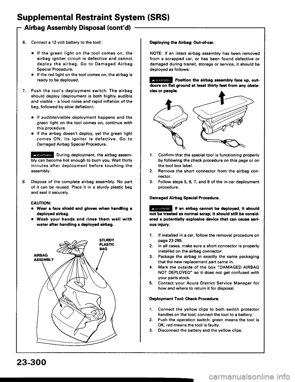
Dispose of the complete airbag sssembly. No pan
of it can be reused. Place it in I sturdy plastic bag
and seal it securelv.
CAUTION:
Woar a taco shiold lnd glov.s whon hlndling !
doploy.d airbag.
Waeh your hands and rin3a tham wall with
wslor aftor handling r deploycd !irb!g.
23-300
Doploying the Airbag: Out-ot{!r.
NOTE: lf an intsct airbag assembly has been removed
from a scrapped car, or has been found dofective or
damagsd during transit, storage or service, it should bs
dsployed as follows:
@ Porition th6 lirbrg rr:.mbly t.ce up, out-
doo6 on flat ground !t lorrt thirty foot from rny ob3t..
clar or pcoplo.
1. Confirm that the special tool is functioning properly
by following the check procedure on this page or on
the tool box label.
2. Remove the short connector from the airbag con-
nector.
3. Folfow steps 5,6,7, and 8 of the in-car deployment
orocequre.
Dlmlged Airbsg Sp.ci8l Procoduro.
E!@ f rn lirbag crnnot be deploy.d, it rhould
not br trcltcd !s normll scrrp; ii 3hould still bc comid-
ercd a potantillly oxplolivr dcvicc thli cln c!u3a 3ari-
ou3 iniury.
1. lf instslled in a car, follow the removal procedure on
page 23-295.
2. In all cases, make sure a short connector is properly
installed on the airbag conn€ctor.
3. Package the airbag in sxacily the same packaging
that the now replacement part cama in.i[. Mark the outside 0f the box "DAMAGED AIRBAG
NOT OEPLOYED" so it does not get confused with
your parts stock.
5. Contact your Acura District Service Manager for
how and where to return it for disoosal.
Dcploymont Tool: Chcck Procedure.
1. Connect the yellow clips to both switch protector
handles on the tool; connect the tool to a battery.
2. Push th€ operation switch: green means the tool is
OK; red means the tool is faulty.
3. Disconnect the battery and the yellow clips.
Page 1406 of 1413
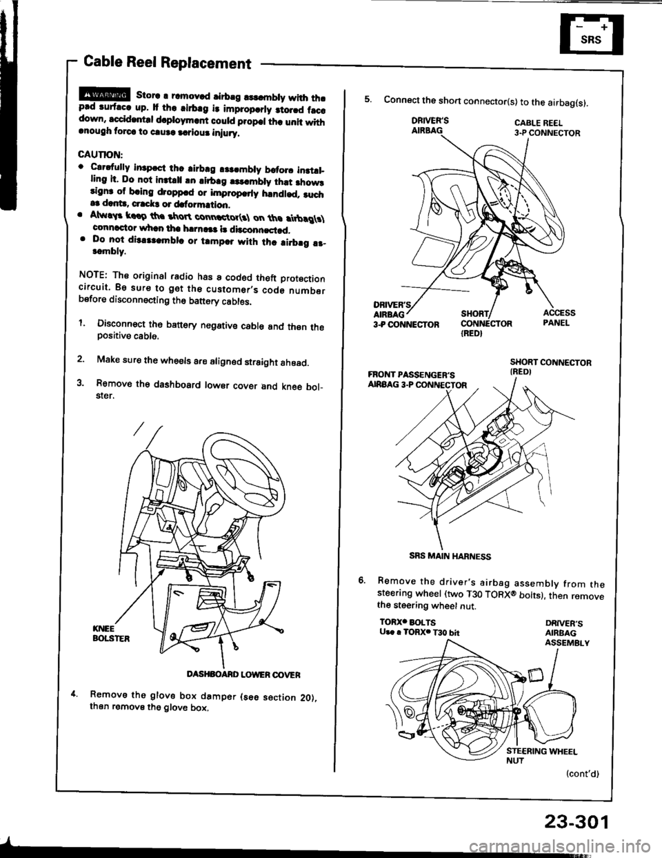
Cable Reel Replacement
!!@ store r rcmov.d rirbrg rsldnbty with thrprd ruf.cc up. It th. .irb.g i3 impropcrly 3to.rd f.ccdown, sccid.ntd d.ploym.rf could propcl th. unit withrnough torca to caure a.?iour iniury.
GAUTION:
o Clrdully in3pcct thc airbrg r$.mbly brtorc instll_ling it. Do not inttrll !n lirb.g |3..mbly ihst fiow3rignr of bring droppcd or improp.rly handled. ruch.3 dant!, crrck3 or dafo?mation.. Atw!$ krro th. tkroR connctot(3l on ths rtbrg \connactor whan tha h|rn!|a l! dbconncstad,. Do lo-t dis.tlambla or tampar with thc ai.brg !r-t.mbly.
NOTE: The original radio has a codod theft Drotoctioncircuit. Bs sure to get the customer,s code numberbsfore disconnecting th6 battery cables.
l. Disconnect th6 banory negstive cable and thsn thepositive cable.
2. Make sure the whe€ls are aligned straight ahoad.
3. Removo th€ dashbosrd lowsr covsr and kne6 bol_$er.
DASHBOANO LOWER OOVER
Removs tho glove box damper (s6e s€ction 2O),then remove the glove box,
-
23-301
IRED}
5. Connect the sho.t connector(s) to the airbag(s).
DRIVER'SAIRBAG
Remove the driver's airbag assembly from thesteerang wheel (two T30 TORXO bolts), then removethe steering wheet nut.
TOR)(' BOLTSU.. . TORX. T30 bhDRIVER'SAIRBAGASSEMBLY
(cont'd)
SRS MAIN HARNESS
Page 1410 of 1413
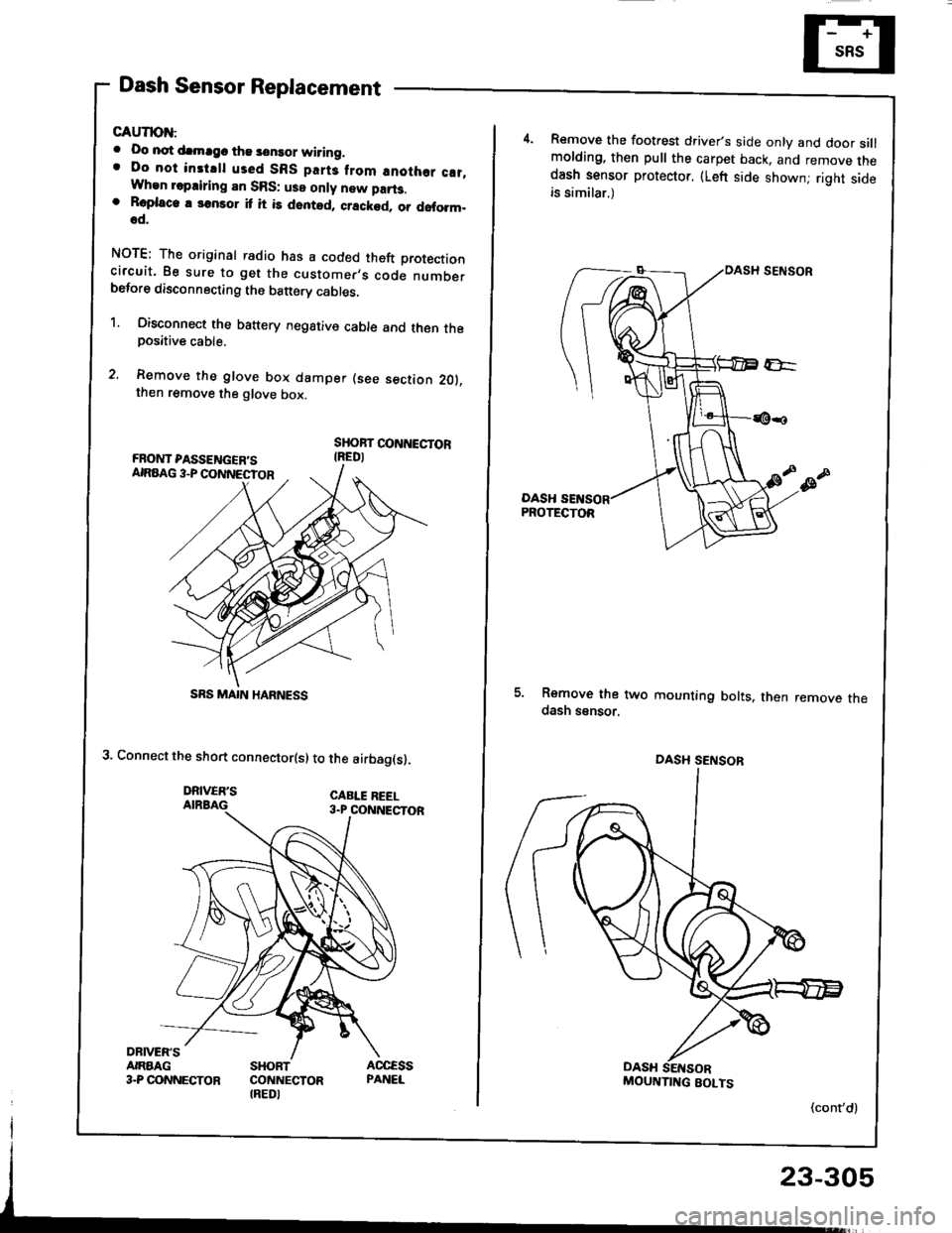
Dash Sensor Replacement
GAUTION:
. Oo not drmrgc the sensor wiring.. Do not instrll used SBS part3 from anothor c!t,When repairing an SRS: use only new part3.o Roplaco. 3onsor it it is dented, crackod, or doform.od.
NOTE; The original radio has a coded theft protectioncircuit. 8e sure to get the customer,s code numberbefore disconnecting the b€ttery cabres,
1. Oisconnect the battery negative cable and then theposative cable.
2. Remove the glove box damper (see section 201.then remove the glove box.
SHOBT CONNECTORIREDI
3. Connect the short connector(s) to the airbag(s).
DRIVER'SAIRBAG
DRNEN'SANAAG3.P CONNECTORSHORTCONNECTORIREDI
SRS MAIN HARNESS
Remove the footrest driver,s side only and door sillmolding, then pull the carpet back, and remove thedash sensor protector. (Left side shownj right sideis similar.)
DASHPROTECTOR
5. Remove the two mounting bolts. then remove thedash ssnsor.
(cont'd)
DASH SENSOB
MOUNTIITG BOLTS
23-305
Page 1412 of 1413
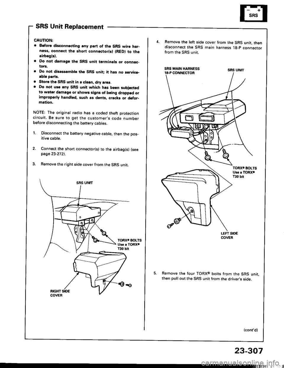
SRS Unit Replacement
CAUTION:
. 8€tor6 disconneciing any part of the SRS wire har-ness, connect the short connectorlsl (RED) to thosirbagl3).
o Do nol drmsgo thc SRS unit terminal! o. connoc-to.s.
. Do not disassemblo tho SRS unit; it ha3 no rervico-.blo parts.
. Storo tho SRS unit in a cleln, dry srea.. Do not us€ lny SRS unit which h.s been subisctodto wator damag€ or shows sign3 ol b€ing droppad orimproperly handl6d, such as dents. cracki or d6tor-mation.
NOTE: The original radio has a coded theft protectioncircuit. Be sure to get the customer,s code numberbefore disconnecting the baftery cables.
1. Disconnect the battery negative cable, then the pos_
itive cable.
Connect the short connector(s) to the airbag(s) (seepage 23-2721.
Remove the right side cover from the SRS unit.
4.Remove the left side cover from the SRS unit. thendisconnect the SRS main harness lg-p connectorfrom the SRS unit.
Remove the four TORXo bolts from the SRS unit,then pull out the SRS unit from the driver,s side.
(cont'd)
SRS UNIT
23-307