Air conditioning HONDA INTEGRA 1994 4.G User Guide
[x] Cancel search | Manufacturer: HONDA, Model Year: 1994, Model line: INTEGRA, Model: HONDA INTEGRA 1994 4.GPages: 1413, PDF Size: 37.94 MB
Page 233 of 1413
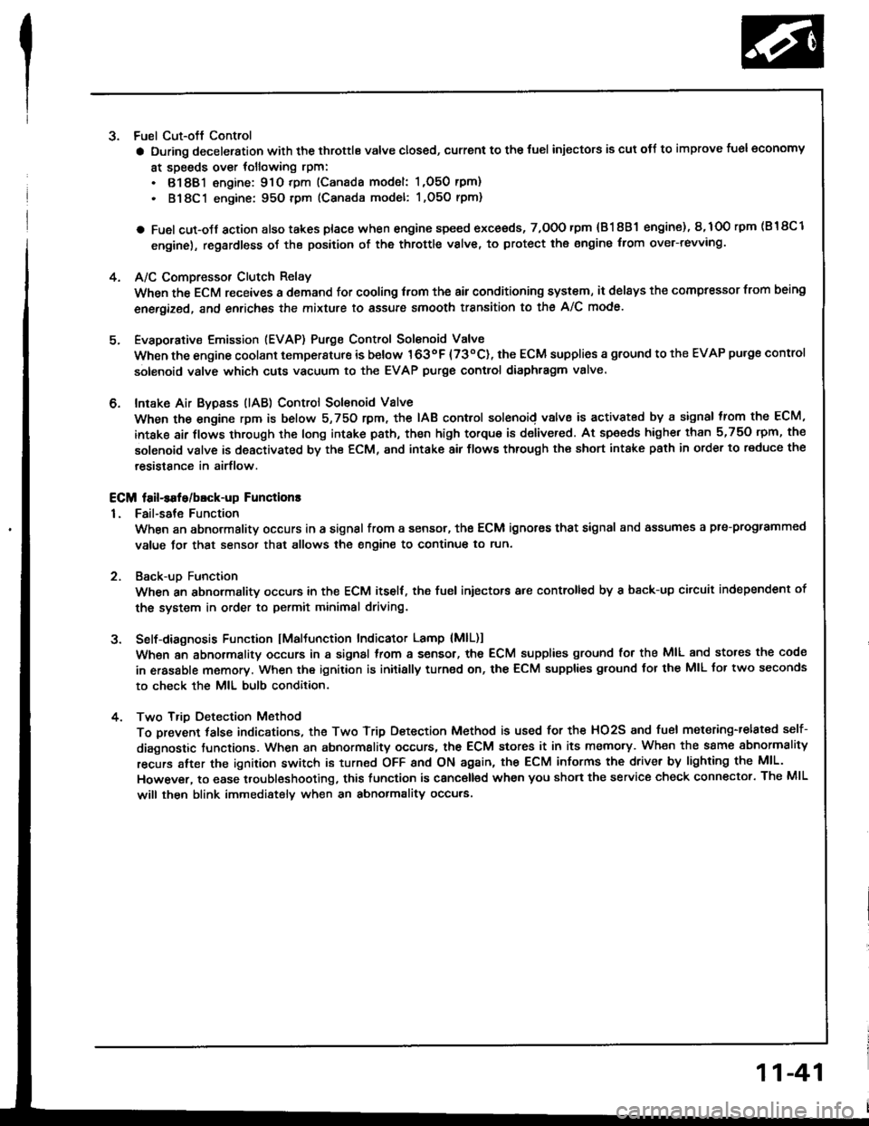
3. Fuel Cut-oft Control
a During deceleration with the throttle valve closed, current to the {uel injectors is cut otJ to improve fuel economy
at speeds over tollowing rpm:
. 8188l engine: 91O tpm (Canada model: 1,O50 rpm)
. 818C1 engine: 95O tpm (Canada model: l,O5O rpm)
a Fuel cut-olf action also takes place when engine speed exceeds, 7,O0O rpm {81 8B1 engine), 8,1O0 rpm (B 18Cl
engine), regardless oI the position of the throttle valve, to protect the engine from ovet-revving.
A/C Compressor Clutch Relay
When the ECM receives a domand for cooling trom the air conditioning system, it del8ys the compressor from being
enetgized, and enriches the mixture to assure smooth transition to the A/C mode.
Evaporative Emission (EVAP) Purge Control Solenoid Valve
When the engine coolant tempersture is below 163oF {73"C), the ECM supplies a ground to the EVAP pu.ge control
solenoid valve which cuts vacuum to the EVAP purge control diaphragm valve.
Intake Air Bypsss (lAB) Control Sol€noid Valve
When the engine rpm is below 5,750 rpm, the IAB control solenoid valve is activated by a signal from the ECM,
intske air flows through the long intake path, then high torque is delivered. At spaeds highe. than 5,750 rpm, the
solenoid valve is deactivated by the ECM, and intake air flows through the short intake path in order to reduce the
resistance in airflow.
ECM fail-safe/bEck-up Functions
1. Fail-sate Function
When an abnormality occurs in a signal from a sensor, the ECM ignores that signal and assumes a pre-progtammed
value tor that sensor that allows the engine to continue to run.
Back-uD Function
When an abnormalitv occurs in the ECM itself, the fuel iniectors are controlled by a back-up citcuit independent of
the system in order to permit minimal driving.
Self-diagnosis Function IMaltunction Indicator Lamp {MlL)1
Wh6n an abnormality occurs in a signal from a sensor, the ECM supplies ground for the MIL and stores the code
in erasable memory. When the ignition is initially turned on, the ECM supplies ground tor the MIL tor two seconds
to check the MIL bulb condition.
Two Trio Detection Method
To prevent tals€ indications, th€ Two Trip Dstection Method is used for the HO2S and fuel metering-related self-
diagnostic tunctions. When an abnormslity occurs, the ECM stores it in its memo.y. Wh€n the ssme sbnormality
recurs alter the ignition switch is turned OFF and ON ag8in, the ECM informs the driver by lighting the MlL.
However, to ease troubleshooting, this function is canc€ll€d when you short the service check connector. The MIL
will then blink immedistelv when an abnormality occurs.
4.
6.
2
4.
11-41
Page 270 of 1413
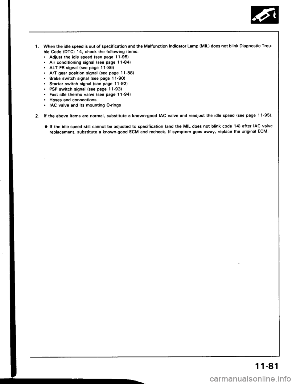
1. when the idls speed is out of specification and the Malfunction Indicator Lamp (MlLldoes not blink Diagnostic Trou-
ble Code (DTC) 14, check the tollowing items:. Adiust the idle speed {see page I1-95). Air conditioning signal (see page l1-84). ALT FR signal (see page '11-86)
A/T gea, position signal (see page 11-88)
Erake switch signal (see page 1 1-90)
Starter switch signal (see page 1l-921
PSP switch signal (see page 1 1-93)
Fast idl6 thormo valve (see page l1-94)
Hoses and connsctions
IAC valve and its mounting O-rings
2. lf the above items are normal, substitute a known-good IAC vslv€ and readjust the idle speed (see page 11-95)'
. It the idle speed srill cannot be adjusted to speciJication (and the MIL does not blink code 14) after IAC valve
roplacement, substitute a known-good ECM and recheck. It symptom goes away, replsce the original ECM.
1 1-81
Page 273 of 1413
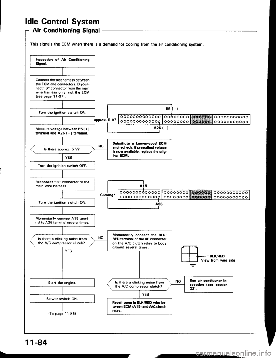
ldle Gontrol System
Air Conditioning Signal
This signals the ECM when there is a demand for cooling from the air conditioning system.
Connect the t€st harness betweenthe ECM and connectors. Discon-nect "B" connector from the mainwire harness onlv, not the ECM{see page 11-37}.
Turn the ignition switch ON.
Measure voltage between 851+ )lerminal and A26 l- I terrninal.
Sub.litut ! known{ood €CMrnd r6
Turn th€ ignition switch OFF.
Reconnect "8" connector to themain wire harness.
Turn the ignilion switch ON.
Momentarilv connect A15 termi-nalto A26 terminsl severaltimes.
Momsntarilv connect the 8LK/RED t€rminal of the 4P connectoron the A/C clutch rel6v to bodyground sevsral times.
ls there a clicking noise fromthe A/C comDressor clutch?
3o6 rlr condhlohar in-rDactlon llaa lac{ion221.
ls there a clicking nois€ lromth€ A/C comoressor clutch?
Rop.ir opon in BLK/BED wiro be-two.n ECM {A15} and A/C clurchrally.
ooooooooooooo
oooooooooooo
oooooooo
oooooooo
ooooooooooo
ooooooooooo
.pprox. 5 V?
426 (- )
Cllcklng?
lTo page
11-84
-
Page 1037 of 1413
Heater and Air Conditioning
Heater ........ 21-1
Air Conditioning .......... ..22-1
SUPPLEMENTAL RESTRAINT SYSTEM {SRS}
The Integra SRS includes a driver's airbag, located in the steering wheel hub. In addition. all models except the
RS model for Canada have a front passenge.'s airbag located in the dashboard above the glovs box. Information
necessary to safely service the SRS is included in this Service Manual. ltems msrk€d with an asterisk (') on the
conlents page include, or are located near, SRS components. Servicing, disassembling or,eplacing thes€ items
will require special precautions and tools, and should therefore be done by an authorized Acura dealer.
a To avoid r6nd6dng tho SRS inoporativo. which could lead to personal injury or dealh in tho svont ot a sevele
frontal collision, all SRS servica work musl b€ portormed by an authorized Acura dealer.
a lmpropor sorvico procaduro3, including incorrect romoval and installatlon of tho SRS, could load to porsonal iniu-
ry causod by uninlonlional activation of tho ailbag8.
a All SRS eloctdcal widng harnossos are covored with yollow in3ulation. Relatsd compononts a.o locatod in tha
stsering column, flont console, daehboard, and dashboafd low6r pan6l, and in lhe dsshboa.d above lh€ glove
box. Do not uao electdcal tost equipmont on theae circuhs.
NOTE: The original radio has a coded theft protection circuit. Be sure to get the customer's code number beto.e
- disconnecting the battery.- removing the No. 32 (7.5 A) luse from the under-hood fuse/relay box.- removing the radio.
After service, reconnect power to the radio and turn it on. When the word "CODE" is displayed, enter the cus-
tomer's 5-digit code to restore radio operation.
Page 1045 of 1413
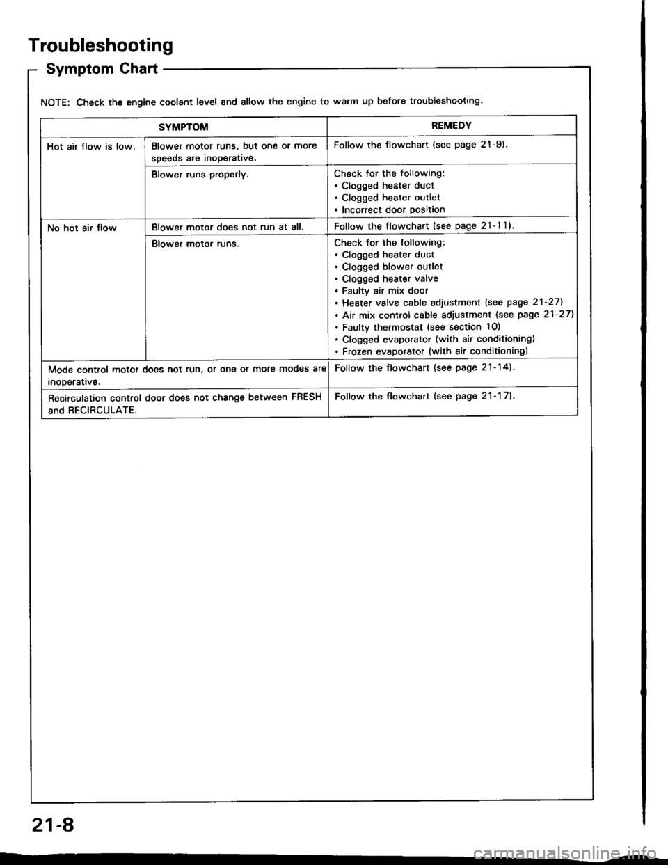
Troubleshooting
Symptom Chart
NOTE: Check the engine coolant level and allow the engine to warm up before troubleshooting.
SYMPTOMREMEDY
Hot air flow is low.Blower motor runs, but one ol more
speeds are inoperative.
Follow the tlowchart (see page 21-9).
Blower runs properly.Check for the following:. Clogged heater duct. Clogged heater outlet. Incorrect door position
No hot air JlowBlowel motor does not run at all.Follow the flowchart (see page 2l-l1l
Blower motor runs.Check for the following:. clogged heatet duct. Clogged blower outlet. Clogged heater valve. Faultv air mix door. Heater valve cable sdjustment lsee page 2'l-271
. Air mix control cable adjustment (see page 21-27)
. Faulty thermostat (see section lO)
. Clogged evaporator (with air conditioning). Frozen evaporator (with air conditioning)
Mode control motor does not run, or one or more modes are
inooerative.
Follow the flowchart (see page 21-14).
Recirculation control door does not change between FRESH
and RECIRCULATE.
Follow the flowchart (see page 21- 17).
21-A
Page 1057 of 1413
Blower Unit
Replacement
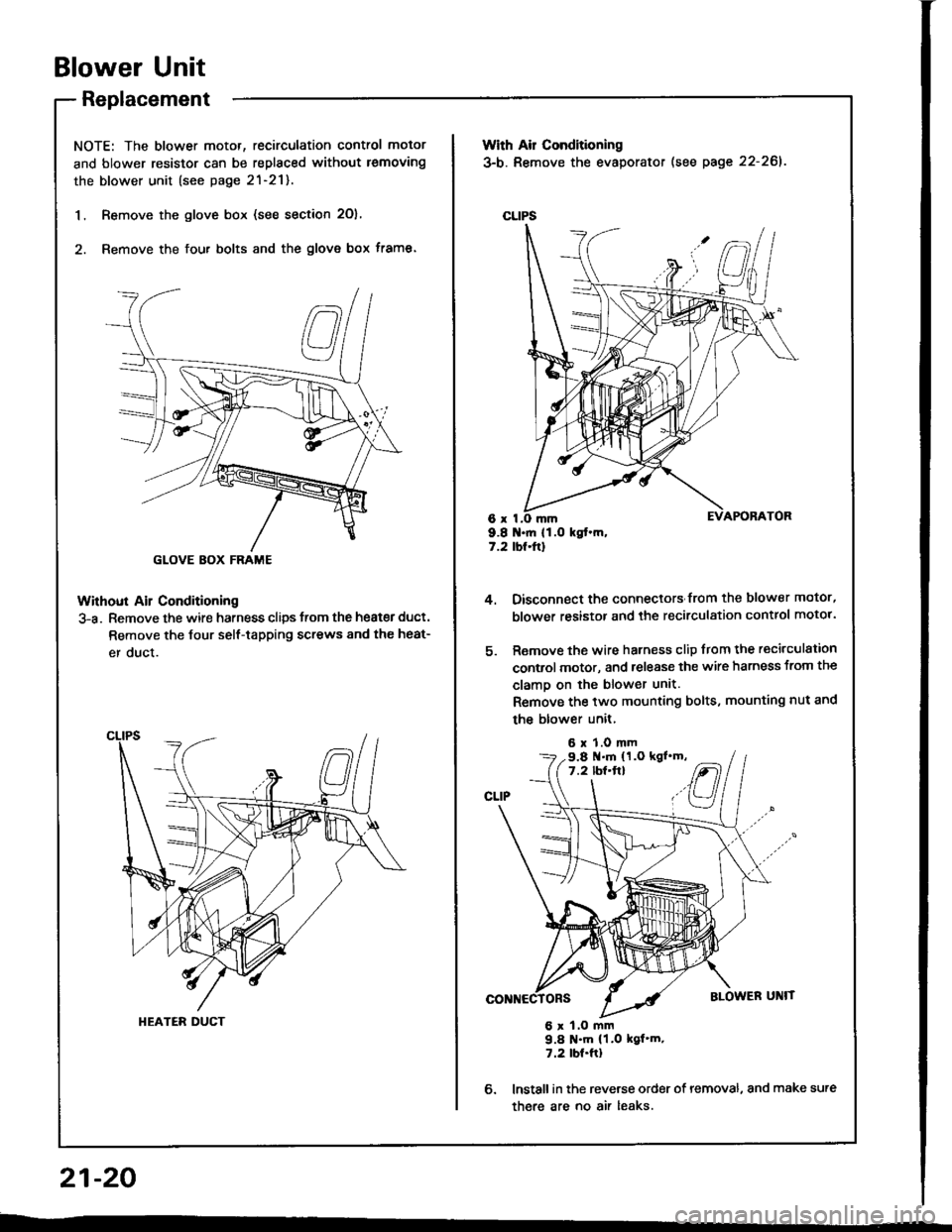
NOTE: The blower motor, recirculation control motor
and blower resistor can be replaced without lemoving
the blower unit (see page 2l-21).
1. Remove the glove box (see section 2O),
2. Remove the fou. bolts and the glove box frame.
Without Ail Conditioning
3-a. Remove the wire harness clips trom the heat€r duct.
Remove the Jour self-tapping screws 8nd the heat-
er duct.
GLOVE BOX FRAME
HEATER DUCT
With Air Conditioning
3-b. Remove the evaporator (see page 22-261.
CLIPS
6x I9.8 .ft 11.O kgt.m,7.2 tbt.ftl
4.
6.
Oisconnect the connectors from the blower motor,
blower resistor and the recirculation control motor.
Remove the wire harness clip from the recirculation
control motor, and release the wire harness from the
clamo on the blower unit.
Remove the two mounting bolts, mounting nut and
the blower unit,
6 x 1.0 mm
6 x 1.O mm9.8 N'm (1.0 kgf'm.7.2 tbt.ftl
lnstall in the reverse order of removal, and make sure
there are no air leaks.
9.8 .m (1.O kgl'm,7.2 lbf'ft}
21-20
--
Page 1069 of 1413
Air Conditioning
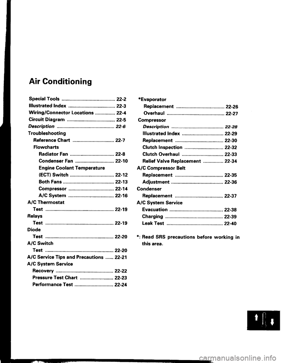
*Evaporator
Repf acement .........22-26
Overhauf ................ 22-27
Compressor
Description ............ 22-28
fffustrated fndex ............................... 22-29
Replacement .........22-30
Cf utch lnspection ....................... ...... 22-32
Cf utch Overhaul ............................... 22-33
Ref ief Vaf ve Replacement ............... 22-34
A/C Compressor Belt
Repf acement .........22-35
Adiustment ............22-36
Condenser
Replacement ......... 22-37
A/C System Service
Evacuation ....,.......,22-38
Charging ................ 22-39
Leak Test ...............22-40
+: Read SRS precautions before working in
this area.
Page 1074 of 1413
Description
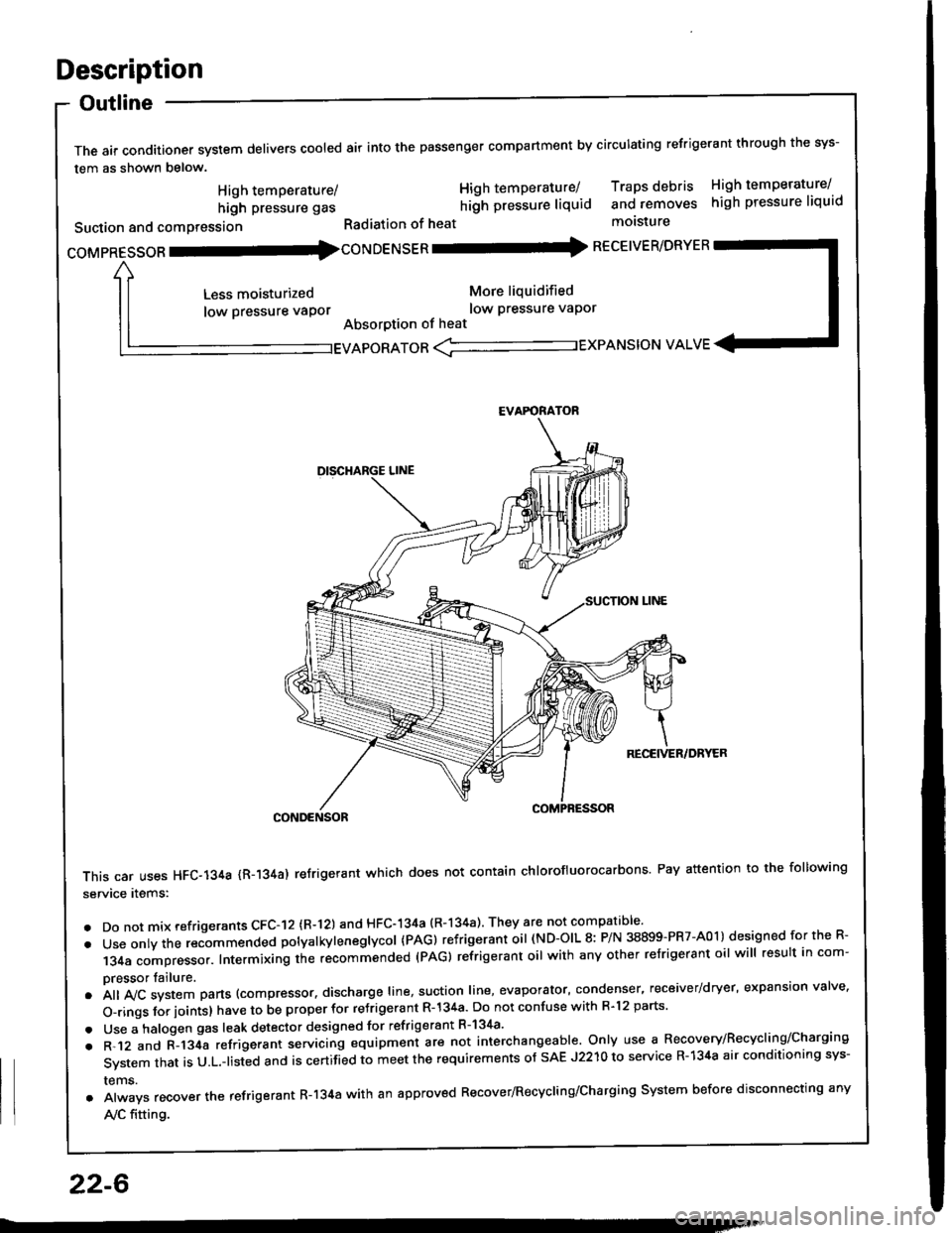
Outline
The air conditioner system delivers cooled air into the passenger compartment by circulating refrigerant through the sys-
tem as shown below.
CONDENSOR
This car uses HFC-134a {R-134a) refrigerant which does not contain chlorofluorocarbons Pay attention to the following
service items:
. Do not mix refrigerants CFC-I2 (R-l21 and HFC-134a (R-134a) They are not compatible'
. Use onty the recommended potyatkytenegtycol {PAG) refrigerant oil (ND-OIL 8: P/N 38899-PR7-A01) designed for the R-
134a compressor. Intermixing the recommended (PAG) refrigerant oil with any other refrigerant oil will result in com-
pressor tailure.
.A||lvcsystemparts(compressor.dischargeIine,suotionIine,evaporator,condenser.receiver/dryer,expansionva|ve.
o-ringsforioints}havetobeproperforre'rigerantR-l34a.DonotconfusewithR.l2parts.
. Use a halogen gas leak detector designed for refrigerant R-134a'
. R-.12 and C-l34a refrigerant servicing equipment are not interchangeable. Only use a Recovery/Recyclins/Charging
System that is U.L.-listed and is certifLd to meet the requirements of sAE J2210 to service R-134a air conditioning sys-
rems.
. Always recover the refrigerant R-134a with an approved Recover/Recycling/Charging System before disconnecting any
A,/C fitting.
coMpRESsoR -coNDENSER - RECEIVER/DRYER
High temperature/
high pressure gas
Suction and comPression
Less moisturized
low pressure vaPor
High temperature/ Traps debris High temperature/
hilh pressure liquid and removes high pressure liquid
Radiation of heat molsture
More liquidified
low Pressure vaPor
Absorption of heat
EVAPORATOR <-'----------.- EXPANSION VALVE
EVAFORATOR
22-6
Page 1089 of 1413
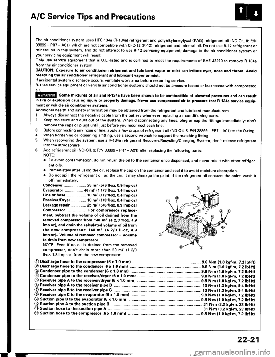
A/C Service Tips and Precautions
The air conditioner system uses HFC-134a (R-134a) .efrigerant and polyalkyleneglycol (PAG) retrigerant oil (ND-OIL g: p/N
38899 - PR7 - A0l ), which are not compatible with CFC-12 \R-'12) refrigerant and mineral oil. Do not use R-12 refrigerant ormineral oil in this system, and do not attempt to use R-'12 servicing equipment; damage to the air conditioner system oryour servicing equipment will result.
only use service equipment that is u.L,-listed and is certified to meet the requirements of sAE J2210 to remove R-134afrom the air conditioner svstem.
CAUTION: Exposure lo air conditioner refrigorant and lubricanl vapor or mi3t cln irritato gyos, nose and throat. Avoidbreathing lhe air conditioner refrigerant and lubricant vapor or mist.
lf accidental system discharge occurs, ventilate work area befor€ resuming service.R-134a service equipment or vehicle air conditioner systems should not be pressure tested or leak tested with compressedair.
@ some mirtures of air and R-l3ifa have been 3hown to be combu3tible at slsvated prossuros and can relultin fire or explosion causing inlury or property damage. Never use complessod ai. to prgssure t€|st R-134a service equip-ment or vehicle air conditiongr systems.
Additional health and safety information may be obtained from the refrigerant and lubricant manufacturers.'1. Always disconnect the negative cable from the battery whenever replacing air conditioning pans.
2. Keep moisture and dust out of the system. When disconnecting any lines, plug or cap the fittings immediately; don'tremove the caps or plugs until just before you reconnect each line.
3. Before con necting a ny hose or line, apply a few drops of refrigerant oil (ND-OIL 8: P/N 38899 - PR7 - AO1) to the O-ring.4. When tightening or loosening a fitting, use a second wrench to support the matching fitting.5. When recovering the system, use a R-134a refrigerant Recovery/Recycling/Charging System; don't release refrigerantinto the atmosDhere.
6. Add refrigerant oil (ND-OlL 8: P/N 38899 - PR7 - A01) after replacing the following parts:
NOTE:
. To avoid contamination, do not return the oil to the container once dispensed, and never mix it with other refriqer-ant orls.
. lmmediately after using the oil, replace the cap on the container and seal ittoavoid moisture absorption,. Do not spill the refrigerant oil on the car; it may damage the paint; if the re{rigerant oil contacts the paint, wash itoff immediately.
Condenser ..................... 25 m/ (5/6 fl.oz, 0.9 lmp.oz)
Evaporator ................. ilo mf 17 113fl.oz,1.4 lmp.oz)
Line or hose 10 ml (1/3 fl.oz. o.il lmp'ozl
Receiver/Dryer .....,.,,...., 10 m{ l1l3 tl.oz, 0.4 lmp.ozl
Leakage repair .............. 25 mf (5/6 fl.oz, 0.9 lmp.ozl
Compressor For compressor .eplaco-
m€nt, subtract the volumo of oil drained from tho
removed compressor trom 140 ml 11 213 ll.oz, 1,9
imp.ozl, and drain the calculalgd volume of oil from
tho new compressor: 140 mf 11 213 ll. oz, 1.9
imp.ozl- Volume ot removod compressor = Volume
to drain from n€w compressor.
NOTE: Even if no oil is drained from the removed
compiessor, don't drain more than 50 ml 11 213
fl.oz, 1.8 lmp .oz) from the new comDressor.
O Dischargo hose to the compresso. (6 x 1.0 mml .............................. 9.8 N.m {1.0 kgt.m, 7.2 lbf.ft)(, Discharge hosa to ths condenser (6 x 1.0 mm) . 9.8 N.m {1.0 kgf.m, j.Z lbl.ftl@ Condenser pipe to tho condenser (6 x 1.0 mml 9.8 N.m n.O kaf.m,t-2tbl.ftl
@ Condenser pipe to the receiver/dryer (6 x 1.0 mm) ......................... 9.8 N.m (1.0 katm,7.2 lbf.ft)@ Receiver pipe A to tho receiver/dryer 16 x 1.0 mm) ......................... 9.8 N.m (1.0 kttm. 7.2 lbt.ft)@ Receiver pipe A to th6 receiver pipe B ......................................
O Receiver pipe B to the receiver pipe C .............................................. 13 N.m {1.3 kgt.m. 9.4 lbt'ft)
13 N.m {1.3 kgf.m.9.4 lbf'ft)@ Receiver pipe C to the evaporator (6 x 1.0 mm) 9.8 N.m {1.0 kgf.m , j.Zlbl.ftl
@Suaion pip€ B to the evaporator {6x 1.0 mm) ................ ................ 9.8 N.m tt.O t!f.-, r.Z tUt tt}@ Sustion pipe A to the suction pipe B .................. 3t N.m (3.2 klnm,23 lbf.ft)(, Suction hose lo the suction pipe A ................ ...... 31 N.m (3.2 kgf.m, 23 tbf.ftl
OA Suction hose to the compressor {5x 1.0 mm} ................ ................. 9.8 N.m 11.0 kgt.m,7.2 lbf.ft)
ET
22-21
Page 1092 of 1413
A/G System Service
Performance Test
The performance test will help determine if the air con-
ditioner system is operating within specitications.
Only use service equipment that is U.L.-listed and is cer-
tified to meet the requirements of SAE J2210 to remove
HFC-134a {R-134a) from the air conditioner system.
CAUTION: Exposure to air conditioner relrig€rant and
lubricant vapor ot mist can irritate eyes, nose and
throat. Avoid breathing the air conditioner rstrigerant
and lubricant vapor or mi3t.
It accidental system discharge occurs, ventilate work
area before resuming service.
R-134a service equipment or vehicle air conditioner sys-
tems should not be pressure tested or leak tested with
comPressed atr.
!@ some mixtures ot air and R'1344 hrv6
been shown to be combustibls at elovatod prsssurel
and can result in firg or explosion causing iniury 01
property damage. Ngvor usg compregsed ail to prossuro
t€st R-134a ssrvice equipment or vohicl€ air conditioner
syst€ms.
Additional health and safety information may be
obtained from the refrigerant and lubricant manufactur-
ers.
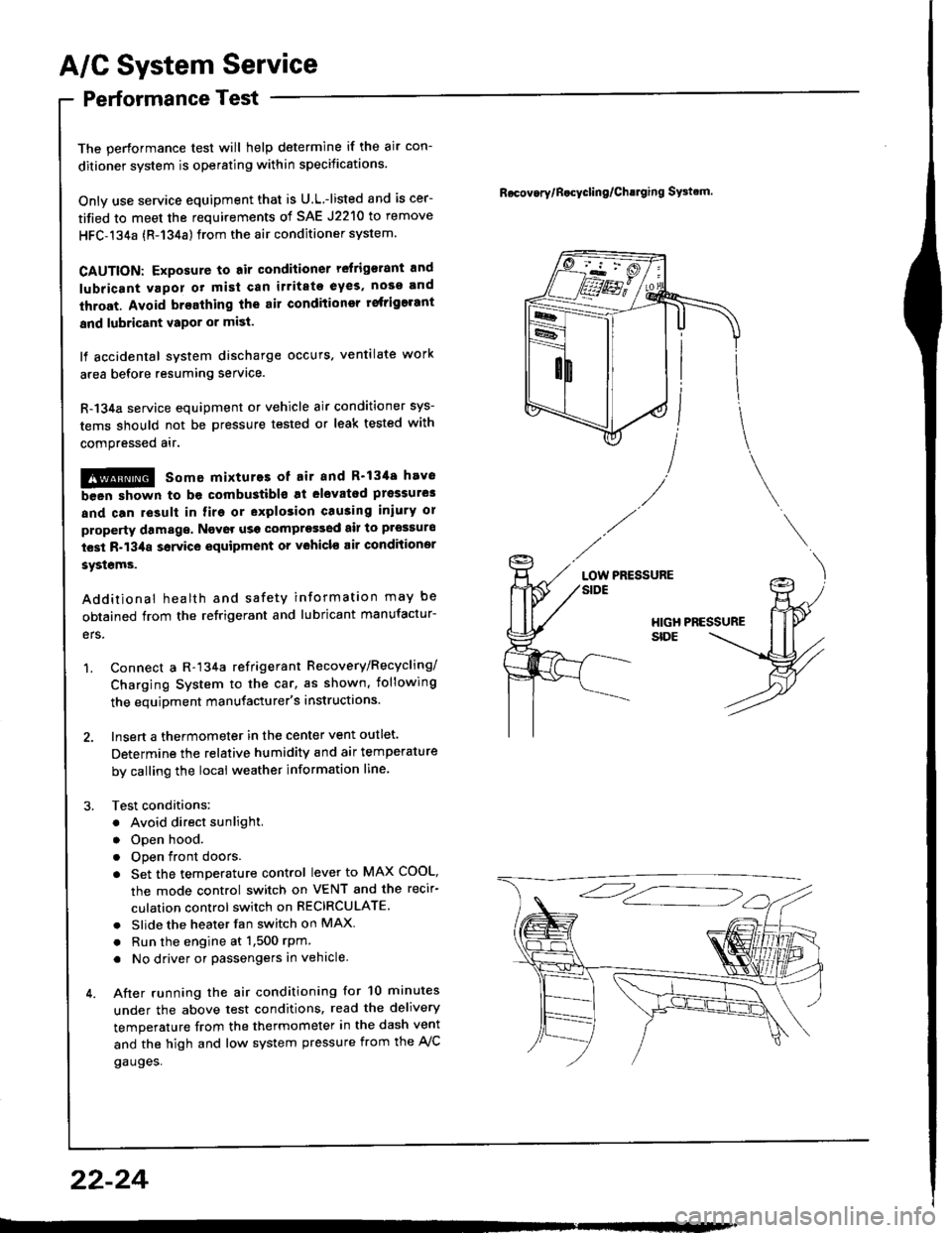
1. Connect a R-134a refrigerant Recovery/Recycling/
Charging System to the car, as shown, iollowing
the equipment manufacturer's instructions.
2. Insert a thermometer in the center vent outlet.
Determine the relative humidity and air temperature
by calling the local weather information line,
3. Test conditions:
. Avoid direct sunlight.
. Open hood.
. Open front doors
. Set the temperature control lever to MAX COOL,
the mode control switch on VENT and the recir-
culation control switch on RECIRCULATE.
. Slide the heater fan switch on MAX
. Run the engine at 1,500 rPm
. No driver or passengers in vehicle.
4. After running the air conditioning for 10 minutes
under the above test conditions. read the delivery
temperature from the thermometer in the dash vent
and the high and low system pressure from the A,/C
gauges.
Rocov.rylB.cycling/Ch!lging SFtrm.
PRESSURELOW
22-24