Piston ring HONDA INTEGRA 1994 4.G User Guide
[x] Cancel search | Manufacturer: HONDA, Model Year: 1994, Model line: INTEGRA, Model: HONDA INTEGRA 1994 4.GPages: 1413, PDF Size: 37.94 MB
Page 110 of 1413
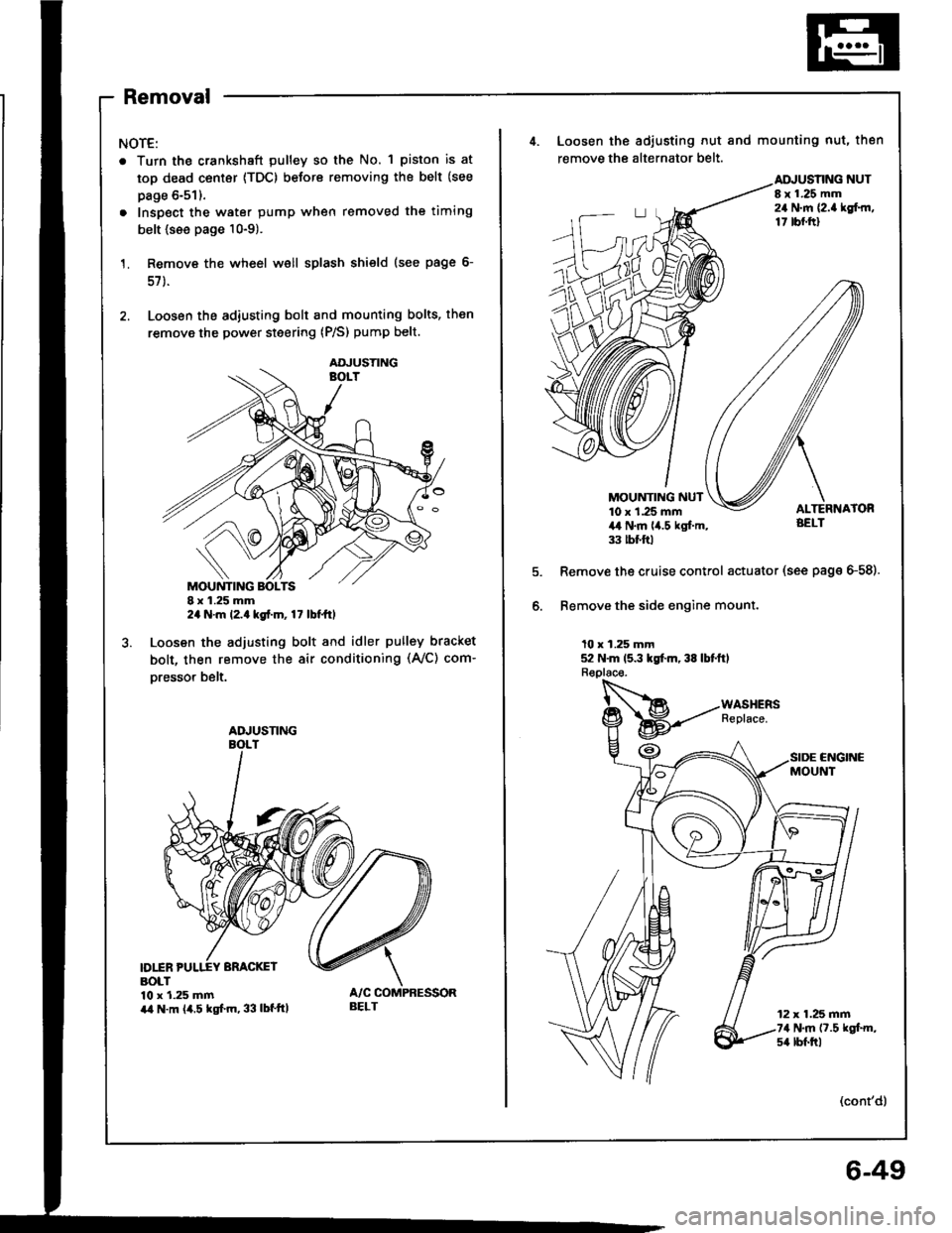
Removal
NOTE:
. Turn the crankshaft pulley so the No. 1 piston is at
top dead center {TDC) before removing the belt (see
page 6-51).
. Inspect the water pump when removed the timing
belt {see page 10-9).
Remove the wheel well splash shield (see page 6-
57 ).
Loosen the adiusting bolt and mounting bolts, then
remove the power steering (P/S) pump belt.
I x 1.25 mm2a N.m l2.a kgt.m, 17 lbt ttl
Loosen the adjusting bolt and idler pulley bracket
bolt, then remove the air conditioning (Ay'C) com-
oresso. belt.
D1INBOLT10 x 1.25 mmira N.m (4.5 kgf.m, 33 lbf'ttl
AOJUSTING
ADJUSNNG
BELT
4. Loosen the adiusting nut and mounting nut, then
remove the alternator belt.
NUTI x 1.25 mm24 N.m {2.a lgf.rn,17 tbf.ftl
MOUNTING NUT10 x 1.25 mm4,t N.m lia.5 kgl.m,33 tbt ftl
Remove the cruise control actuator (see page G58).
Bemove the side engine mount.
10 x 1.25 mm52 N.m 15.3 kgt m, 38 lbtftl
CNGINCMOUNT
12 x 1.25 mm74 N.m (7.5 kgt m,s4 lbf.trl
(cont'd)
6-49
Page 136 of 1413
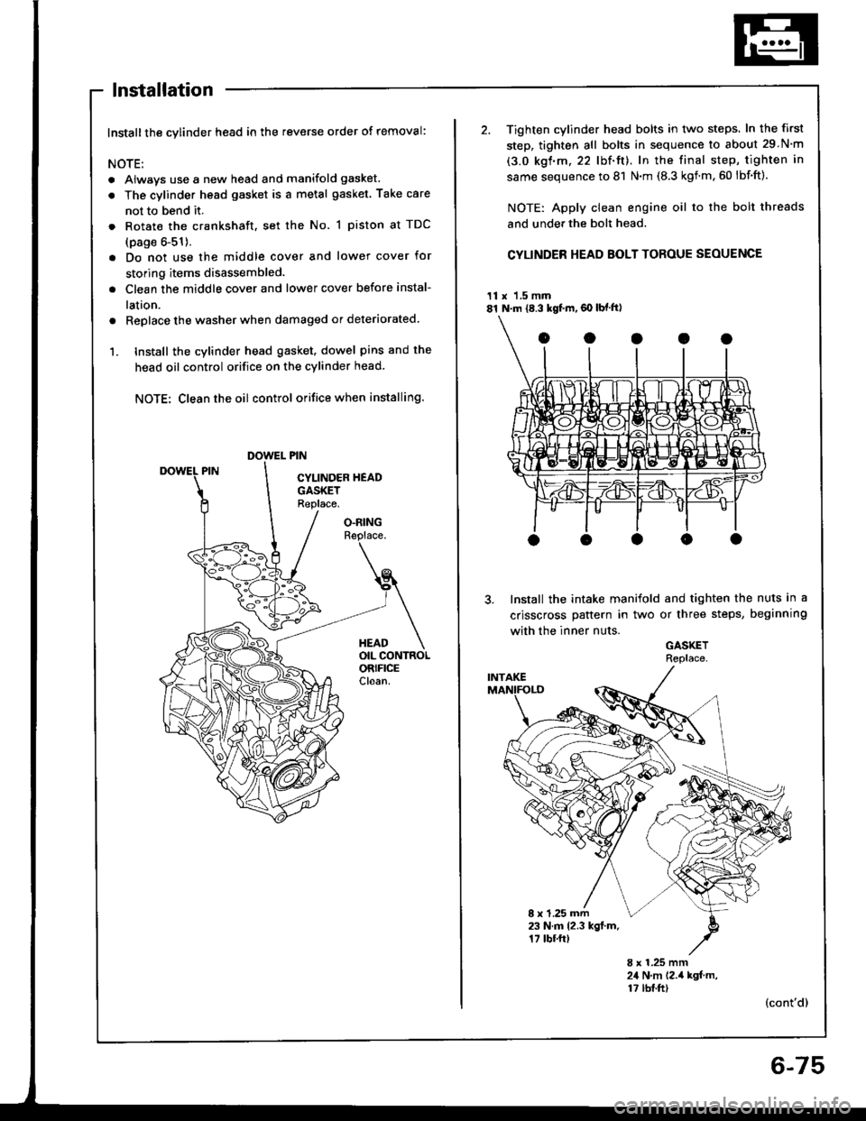
lnstallation
Installthe cylinder head in the reverse order of removal:
NOTE:
. Always use a new head and manifold gasket.
. The cylinder head gasket is a metal gasket Take care
not to bend it.
. Rotate the crankshaft, set the No. 1 piston at TDC
(page 6-51).
. Do not use the middle cover and lower cover for
storing items disassembled.
. Clean the middle cover and lower cover before instal-
lation.
a Replace the washer when damaged or deteriorated
1. tnstall the cylinder head gasket. dowel pins and the
head oil control orifice on the cylinder head
NOTE: Clean the oil control orifice when installing.
O.RINGReplace.
HEADOIL CONTROLORIFICECloan.
2. Tighten cylinder head bolts in two steps. In the first
step, tighten all bolts in sequence to about 29 N'm
(3.0 kgf.m.22 lbf'ft). In the final step, tighten in
same sequence to 81 N.m (8.3 kgnm.60 lbf'ft).
NOTE: Apply clean engine oil to the bolt threads
and under the bolt head.
CYLINDER HEAD BOLT TOROUE SEOUENCE
11 x 1.5 mm81 N.m {8.3 kgf.m,60 lbf ft)
Install the intake manifold and tighten the nuts in a
crisscross pattern in two or three steps, beginning
with the inner nuts.
GASKETRePlace
8 x 1.25 mm23 N.m 12.3 kgl.m.17 tbf.ftt
8 x 1.25 mm24 N,m 12.,4 kgf m,17 tbf.ft)(cont'd)
6-75
Page 141 of 1413
Engine Block
Speciaf Tools .............7'2
lllustrated Index ................................... 7-3
Flywheel and Drive Plate
Repfacement .........7-7
Main Bearings
Clearance ,.............. 7-8
Selection ................ 7-8
Connecting Rod Bearings
Clearance ............... 7-9
Selection ................ 7-9
Crankshaft
Removal .................7-10
End Play .................7-12
lnspection ........,,,.,,7-12
fnstallation .............7'22
Cylinder Block
Inspeetion ..............7-13
Bore Honing .....,.,,.7'14
Pistons
Inspaction ..............7-15
Installation .............7-16
Piston Rings
Replacement .........7-16
End Gap .................7-17
Ring-To-Groove C|earance,,,,.,,,...... 7 -17
Alignment ..............7-18
Piston Pins
Removal ........,........7-18
Installation (818B1 engine) ............. 7-19
fnstaffation (818C1 enginel ............. 7-20
fnspection ..............7-2O
Connecting Rods
End Play .................7-21
Sefeetion ..........,,,,,,7-22
Oil Seal
fnstaffation .............7-25
Installation
(engine removal not requiredl.. .......7-26
Page 142 of 1413
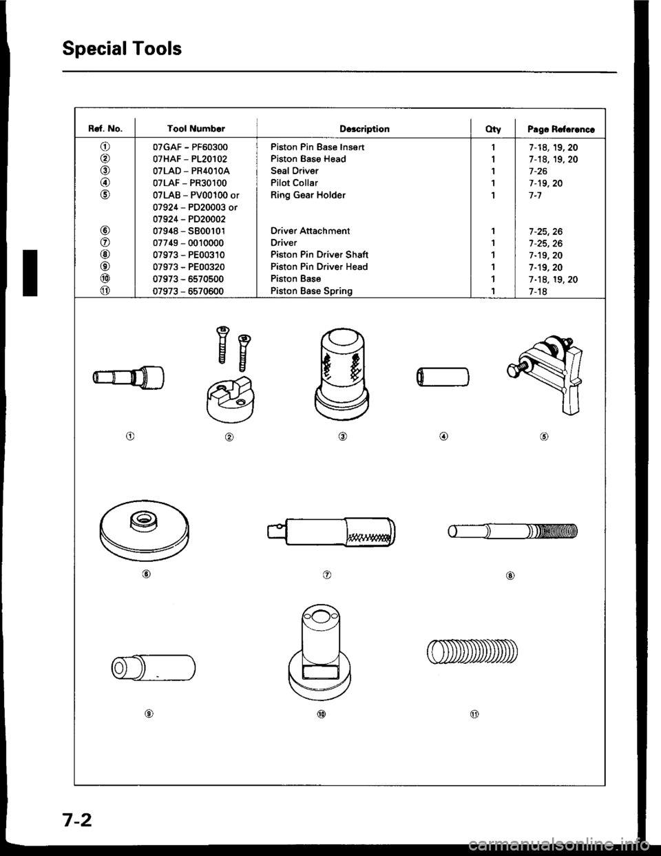
Special Tools
I
Raf. No. I Tool NumbcrDcacriptionOty I Pago Rotcrenc.
o
@
@
@
o
@
o
@
o
@
o
07GAF - PF60300
07HAF - P120102
OTLAD _ PR4O1OA
07LAF - PR30100
07LAB - PV00100 or
07924 - PD20003 or
01924 - PD20002
07948 - S800101
07749 - 0010000
07973 - PE00310
07973 - PE00320
07973 - 5570500
07973 - 6570600
Piston Pin Ease lnsert
Piston Base Head
Seal Oriver
Pilot Collar
Ring Gear Holder
Driver Attachment
Driver
Piston Pin Driver Shaft
Piston Pin Driver Head
Piston Base
Piston Base Spring
1
I
1'I
1
1
1
1
1
1
1
7-14,19,20
1-18, 19,20
7-19,20
7-1
7 -25, 26
7-19,20
1-19.20
1-18, 19, 20
1-18
Eg
o@,a\
o@
@@
0
7-2
Page 146 of 1413
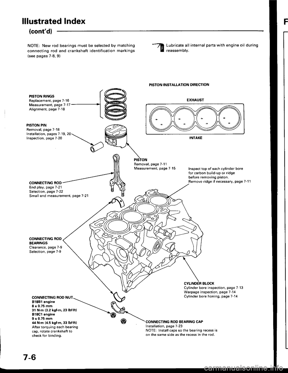
lllustrated IndexF
(cont'd)
NOTE: New rod bearings must be selected by
connecting rod and crankshaft identification
(see pages 7-8,9)
matching
marKrngs
Lubricate all internal parts with engine oil during
reassemorv.
PISTON RINGSReplacement, page 7'16Measurement. page 7-17Alignment, page 7 18
PISTON PINRemoval, page 7-18lnstallation, pages 7 19, 20Inspection, page 7'20
PISTON INSTALLATION DIRECTION
EXHAUST
INTAKE
Removal, page 7'11Measurement, page 7 15Inspect top of each cylinder borefor carbon build-up or ridgobetore removing piston.Remove ridge it necessary, page 7'11CONNECTING ROOEnd play, page 7-21
CONNECTING RODEEARINGSClearance, page 7-9Selection, page 7-9
CONNECTING ROD NUT818B1 ongine8x 0.75 mm31 N.m {3.2 kgf.m,23 lbf ftl818C1 engine9 x 0.75 mma,a N.m (4.5 kgt m, 33 lbf.ft|After torquing each bearangcap, rotate crankshaft tocheck for binding.
r-(,
Selection, page 7-22Small end measurement. page 7-21
BLOCXCylinder bore inspection, page 7 13Warpage inspection, page 7'14Cylinder bore honing, page 7-14
CONNECTING ROD BEARING CAPInstallation, page 7'23NOTE: Install caps so the bearing recess ison the same side as the recess in the rod.
r@
-1@
Page 151 of 1413
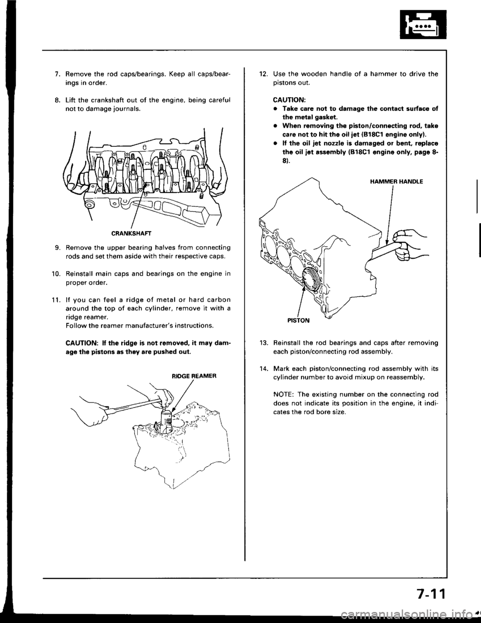
7.
8.
11.
9.
10.
Remove the rod caps/bearings. Keep all caps/bear-
ings in order.
Lift the crankshaft out of the engine, being careful
not to damage journals.
Remove the upper bearing halves from connecting
rods and set them aside with their resDective caDs.
Reinstall main caps and bearings on the engine in
oroDer order.
lf you can feel a ridge of metal or hard carbon
around the top of each cylinder, remove it with a
ndge reamer.
Follow the reamer manufacturer's instructions.
CAUTION: It the ridge is not removed, it may dam-
age the pistons as they are pushed oul.
CRANKSHAFT
RIDGE REAMER
12. Use the wooden handle of a hammer to drive the
prslons ouI.
CAUTION:
a Take care not to damage the contact surfaco ot
the metal gasket.
. When removing the piston/connecting rod, taks
caro not to hit the oil iot {818C1 sngins onlyl.
. It tho oil iet nozzlo is damag6d or bont, replaco
the oil ist assembly (818C1 engine only, page 8-
8).
Reinstall the rod bearings and caps after removing
each piston/connecting rod assembly.
Mark each piston/connecting rod assembly with its
cylinder number to avoid mixup on reassembly.
NOTE: The existing number on the connecting rod
does not indicate its position in the engine, it indi-
cates the rod bore size.
13.
14.
7-11
Page 153 of 1413
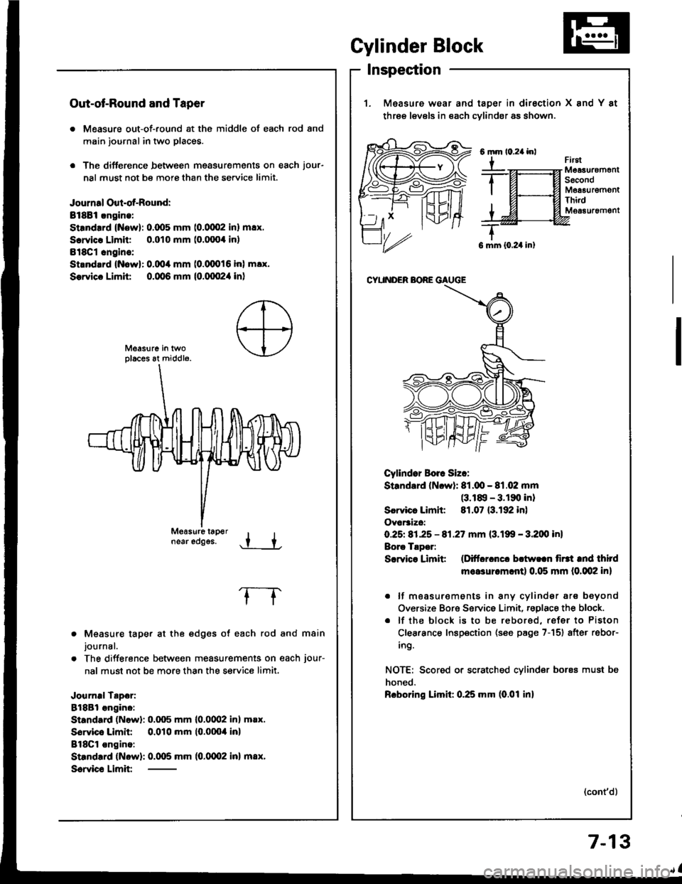
Out-ot-Round and Taper
. Measure out-of-round at the middle of each rod and
main journal in two places.
. The difference between msasurements on each jour-
nal must not be more than the se.vice limit.
Journal Oul-of-Round:
Bt8Bi.ngine:
Strndrrd (Now): 0.(x15 mm (0.0002 inl m!x.
Scrvicr Limit 0.010 mm (o.fixx inl
Bl8Cl cngins:
Strnd.rd {Nowl: 0.004 mm (0.(XD16 inl m!x.
Sorvicc Limit 0.qt6 mm {0.qx!2,1 in}
near edggs..t +
Measure taper at the edges of each rod and main
journal.
The difference between measurements on each jour-
nal must not be more than the service limit.
Journal Tapor:
8l8Bl angino:
Standard (Newl: 0.q)5 mm l0.0(Xl2 inl m.x.
Sorvico Limit 0.010 mm (0.0004 inl
BlSCl ongino:
Standrrd (Now): 0.005 mm (0.0002 inl m8x.
Scrvic€ Limit
frrgtMeaauremonlSecondMoa6urgmontThi.dM063uremgnt
G mm {0.24 in}
CYUNDER BORE GAUGE
Cyllndor Borr Siz.:
Standard (Ncwl: 81.q!- 81.02 mm(3.18, - 3.190 inl
Scrvicr Limh: 81.07 (3.192 in)
Ovar3izc:
O.25t 81.25 - 81.27 mm (3.199 - 3.200 inl
Borc Tlpor:
Scrvice Limit (Ditfcrcncc bctw!.n firtt tnd third
moasurcm.ntl 0.115 mm (0.002 in)
. lf moasur€ments in any cylindsr are beyond
Oversize Bore Service Limit, rsglace the block.
. lf the block is to be rebored, refer to Piston
Clearance Inspection (see page 7-151 after rebor-
ing.
NOTE: Scored or scratched cylinder bores must be
honed.
Rcboring Limil: 0.25 mm (0.01 inl
(cont'd)
Gylinder Block
Inspection
1. Measure wear and taDer in dirsction X and Y at
three levels in each cvlindsr as shown.
6mm
Y
7-13
Page 156 of 1413
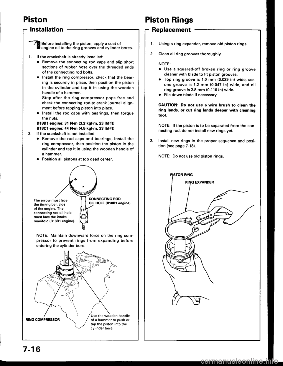
Piston
lnstallation
'1.
Before installing the piston, apply a coat ofengine oil to the ring grooves and cylinder bores.
lf the crankshaft is already installed:
. Remove the connecting rod caps and slip short
sections of rubber hose ove. the threaded ends
of the connecting rod bolts.
a Install the ring compressor, check that the bear'
ing is securely in place, then position the piston
in the cylinder and tap it in using the wooden
handle of a hammer.
Stop after the ring compressor pops free and
check the connecting rod-to-crank journal align-
ment before tapping piston into place.
. Install the rod caps with bearings, then torque
the nuts,
81881 ongino: 31 N.m {3.2 kgf.m, 23 lbf.ftl
818C1 cngino: 44 N'm 1,t.5 kgf.m, 33 lbf.ftl
lf the crankshaft is not installed:
o Remove the rod caps and bearings. install the
ring compressor, then position the piston in the
cylinder and tap it in using the wooden handle of
a nammer.
. Position all Distons at toD dead center.
CONNECTING RODOIL HOI-E (Br8Bl onginelThe arrow must facethe timing belt sideof the engine. Theconnecting rod oil holemust lace the intak€manifold {81881 €ngine).
NOTE: Maintain downward force on the ring com-
pressor to prevent rings from expanding before
entering the cylinder bore,
BING COMPRESSORUse the wooden handleof a hammer to push ortap the piston into thecylinder bore.
Piston Rings
Replacement
1.Using a ring expander, remove old piston rings.
Clean all ring g.ooves thoroughly.
NOTE:
. Use a squared-oJf broken ring or ring groove
cleaner with blade to fit piston grooves.
. Top ring groove is 1.0 mm (0.039 in) wide, sec-
ond groove is 1.2 mm (0.047 in) wide. and oil
ring groove is 2.8 mm (0.110 in) wide.. File down blade if necessary.
CAUTION: Do not use a wire brush to cloan thr
ring lands, or cut ring lands dsopo. with cl€aning
tool.
NOTE: lf the piston is to be separated from the con-
necting rod, do not install new rings yet.
Install new rings in the prope. sequence and posi-
tion (see page 7-18).
NOTE: Do not use old piston rings.
Page 157 of 1413
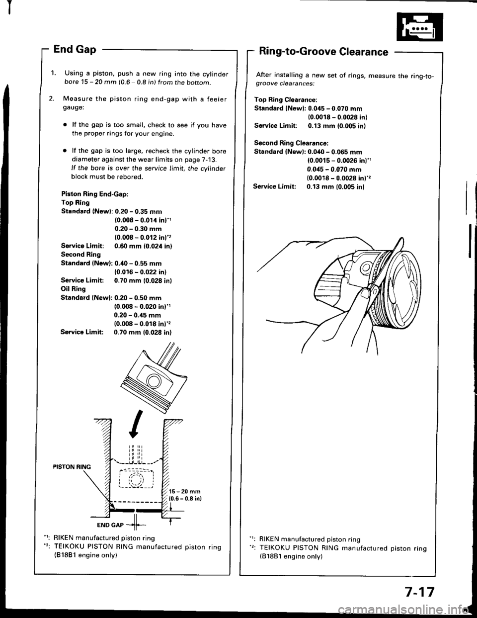
I
'1. Using a piston, push a new ring into the cylinderbore 15 - 20 mm (0.6 0.8 in) from the boftom.
Measure the piston ring end-gap with a feelergauge:
lf the gap is too small. check to see if you have
the proper rings for your engine.
lf the gap is too large, recheck the cylinder bore
diameter against the wear limits on page 7-13.
ll the bore is over the service limit, the cylinder
block must be rebored.
Piston Ring End-cap:
Top Ring
Standard (New): 0.20 - 0.35 mm(0.008 - 0.01'l inl'1
0.20 - 0.30 mm
10.008 - 0.012 inl''
Servica Limit: 0.60 mm (0.024 in)
Second Ring
Standard (Now): 0.40 - 0.55 mm
10.016 - 0.022 in)
Service Limit: 0.70 mm (0.028 in)
Oil Ring
Standard (New): 0.20 - 0.50 mm(0.008 - 0.020 in)'1
0.20 - 0.,15 mm
{0.008 - 0.018 inl',
Servica Limit: 0.70 mm 10.028 in)
After installing a new set of rings, measure the ring-to-gfoove clearances:
Top Ring Cl€arance:
Standard lNewl: 0.045 - 0.070 mm
10.0018 - 0.0028 in)
Service Limit: 0.13 mm {0.005 inl
Second Ring Clearance:
Standard {Newl: 0.040 - 0.065 mm(0.0015 - 0.0026 inl'1
0.0i15 - 0.070 mm(0.0018 - 0.0028 in)',
Service Limit: 0.13 mm (0.005 inl
iliiii.--r.llli.j- --.-PISTON NING
ioi
---'z llEND GAP -11--
RIKEN manufactured piston ring
TEIKOKU PISTON RING manufactured oiston rinq
{81881 engine only)
RIKEN manufactured piston ring
TEIKOKU PISTON RING manufactured Diston rino(B'1881 engine only)
7-17
Page 158 of 1413
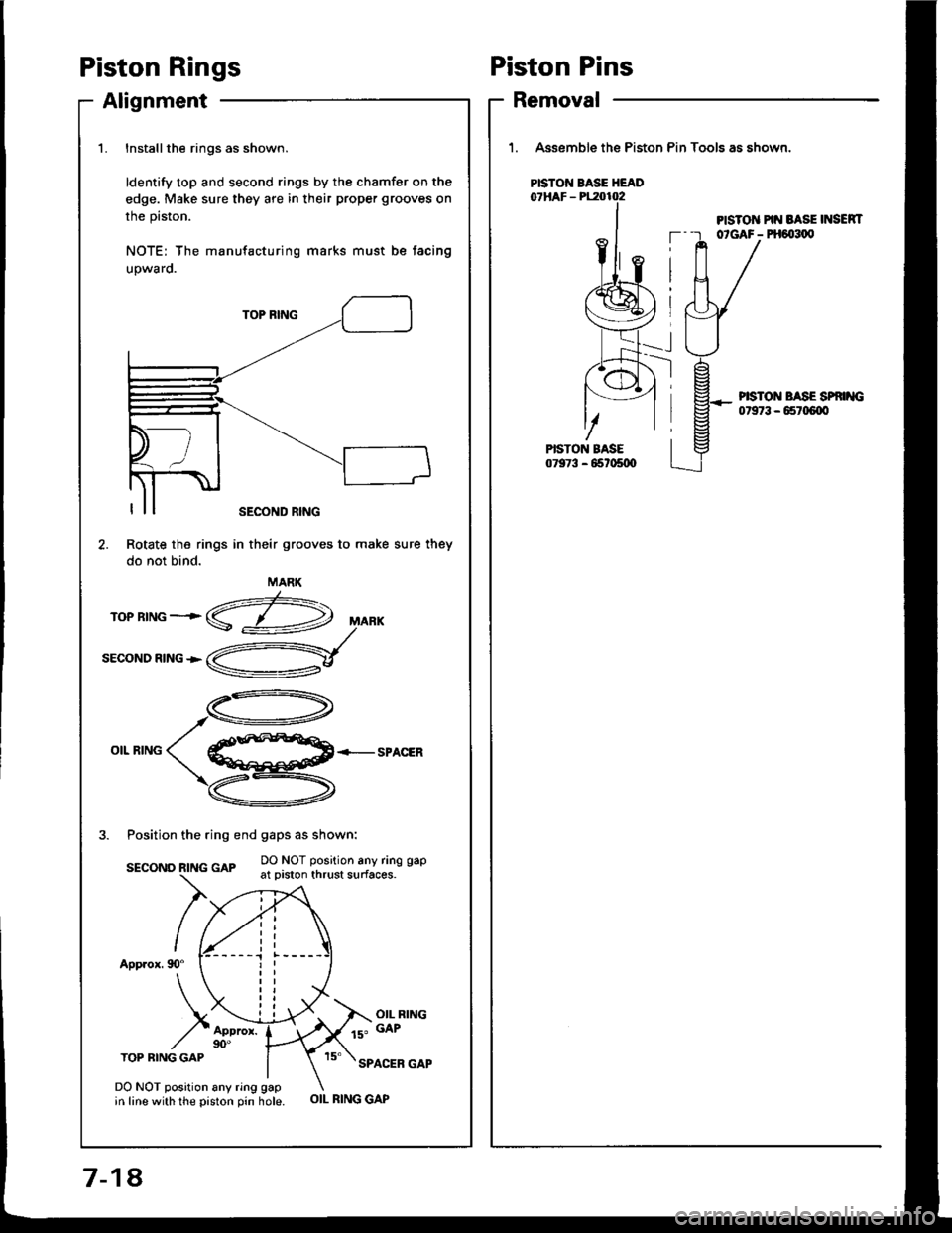
Piston Rings
Alignment
1.Installthe rings as shown.
ldentify top and second rings by the chamfer on the
edge. Make sure they are in their proper grooves on
the prston.
NOTE: The manufacturing marks must be facing
upwaro.
TOP BING
OIL RINGSPACER
3. Position the ring end gaps as shown:
DO NOT position any ring gapsEcoNo R|NG GAp -.- :': :.-"' : - ' '----'-- { _- - - at prston thrust surfaces.
App.ox. 90"
OIL RING
ls" GAP
TOP BING GAPSPACER GAP
Rotate the rings
do not bind.
DO NOT position any ring gapin line with the piston pin hole.
SECOND RING
in their grooves to make sure they
MARK
OIL RING GAP
Piston Pins
Removal
1. Assemble the Piston Pin Tools as shown.
PISTO]T PIN BASE INSEN|T--r otGAF- PH6{t1,0
PISTON BASE HEAD
--l
PISTON BASE SP '{G07973 - 65r06{X'
7-18,