engine wire harness HONDA INTEGRA 1994 4.G User Guide
[x] Cancel search | Manufacturer: HONDA, Model Year: 1994, Model line: INTEGRA, Model: HONDA INTEGRA 1994 4.GPages: 1413, PDF Size: 37.94 MB
Page 242 of 1413
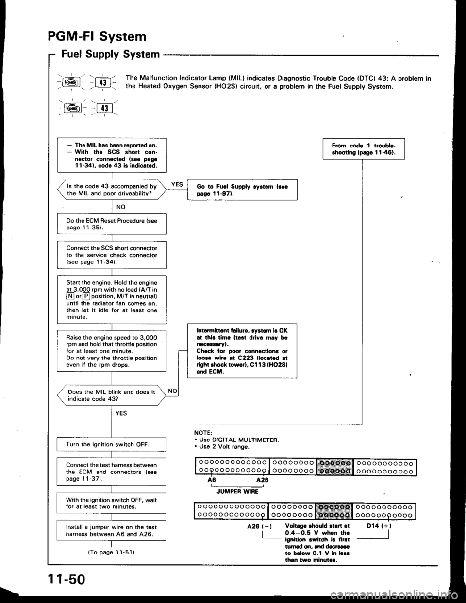
PGM-FI System
rj-t
--t-.
Fuel Supply System
-+-lt@t- -t 13 |- ' "- - --i--
T,-n The Maltunction Indicator Lamp (MlL) indicares Diagnostic Trouble Code (DTC) 43: A problem in
- L:!-i - the Heated Oxygen Sensor (HO2S) circuit. or a probtem in the Fuel Supply System.
NOTE:. Use DIGITAL MULTIMETER.. U6e 2 Volt rang6.
o oooooo oooooo I oo oooooooooooooooooooQoo ooo ooooo I oooo ooooooooooooooo
426
JUMPER WIRE
o ooooo oooo ooo I oo oooooo Isdtcllodsl ooo ooooooooo oooo ooo oo ooo I oooo ooooooooooooooo
D14 {+l
I
426 t-l vohrgo rhould rl.n.t
| 0.4-0.5 V wh.n th..- ignirioo .wilch i! firdt|rtrod o.r, Itd docr!6ato b.low O.1 V in L..th6n two minutaa.
- Tho MIL h.s boen reportod on.- With rhe SCS short con-noctor connocted (soo paga1l-34), codo 43 b indlcat.d,
From codr I troebl.-lhoorlng lprgo 1146).
ls the code 43 accompanied bythe MIL and poor driveability?Go to Fuol Supply .y.t.m (|ecpag6 1t-971.
Do the ECM Reset ftocedure lseepage 11-35).
Connect the SCS short connectorto the service check connector{see page 'l1-34).
Start the engine. Hold the engineat 3,00O rDm with no load {A/T in
@or@ position, M/T in neutral)until the radiator Ian comes on,then let it idle for at least onemanute,
Intonnitl.nt t llure, tydom lr OKat thi. tim. lto.t drlv. mly b.nocaararyr.Chock lor poo? connactlona otloots wiro at C223 lloc.t.d atrlghl lhock towo.]. Cl13lHO2Sland ECM,
Raise the engine speed to 3,000rpm and hold that throttle positiontor at least one minute.Do not vary the throttle positioneven if the rpm drops.
Ooes the MIL blink and does itindicate code 43?
Turn the ignition swilch OFF.
Connect the test harness betweenthe ECM and conneclors {seepage 1 1-371.
With the ignition switch OFF, waitfor at least two minutes.
lnstall a jumper wire on the testharness between A6 and A26.
11-50
1To page 1 1-5'l l
Page 245 of 1413
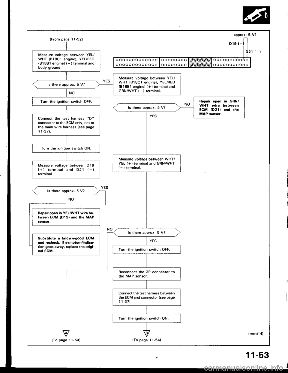
Measure voltage between YEL/WHT {818C1 engine), YEL/RED(B188'1 engine) {+ ) terminal andbodv ground.
Measure voltage between YEL/WHT (818C1 engine), YEL/RED{B1881 engine) (+ } terminal andGRN/WHT (- ) terminal.
ls there approx. 5 V?
Repair opon in GRN/WHT wir6 botweonECM lD2l l and thoMAP sonsor,
Turn the ionition switch OFF.
ls there approi. 5 V?
Connect the test harness "D"
connector to the ECM only, nottothe main wire harness {see page11,37).
Turn the ignition switch ON.
Measure voltage betweon wHT/YEL (+ ) terminal and GRN/WHT{- } terminal.Measure voltage between D19{+} terminal and D21 {-}termrnat,
ls there approx. 5 V?
Bepair open in YEL/WHT wi.e be-tw€6n ECM lD19) and tho MAPaon30t.
ls there approx. 5 V?
Substitule s known-good ECMand rechock. ll symptom/indica'tion goes away, replac€ tho oiigi'nal ECM.Turn the ignition switch OFF.
Reconnecl the 3P connector tothe MAP sensor.
Connect the test harness betweenthe ECM and connector (see page1 1-371.
Turn the ignition switch ON.
11,52)
{To page 11-54}lTo page I l-54)
(cont'd)
Page 263 of 1413
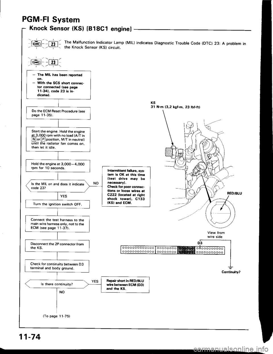
PGM-FI System
Knock Sensor (KS) tB18C1 enginel
ml- nl: The Malfunction Indicator Lamp (MlL) indicates Diagnostic Troubte Code (DTC) 23: A probtem inthe Knock Sensor (KS) circuit.
a6l--fzt.i--1/.---r+\
ware sido
o ooooo ooo ooo o looooooooo oooo ooo oo ooo I oooo oooo
11-74
- The MIL h6s boon r6port6don.- With th6 SCS ahort connec-tor connoctod (soe pago11-341, codo 23 is in-dicrtod.
Oo the ECM Reset Proceduro (seepage 11-35).
Start the engine. Hold the engineg!-3,Opq rpm with no load {A/T in
Lryl orlPlposirion, M/T in neurra until the radiator fan comes on,then let it idle.
Hold the engine at 3,0O0-4,000rpm for 10 seconds.Intomittor failure, ay5-t.m is OK at this tim6(teat drivo mav bonec€saary,.Chock tor Door connec-tion3 or loo3o wlaos etC222 {locatod 6r ghrshock tow6r), Cl33(KSl and ECM.Turn the ignition swirch OFF.
Connect the test harness to themain wire harness only, not to theECM (see page 1 1-37).
Check for continuity between D3terminal and body ground.
Ropdr short in RED/BLUwiro b€tweon ECM {D3land ths Ks.
(To page 11-75)
Page 275 of 1413
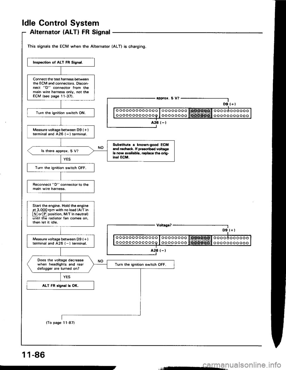
ldle Control System
Alternator (ALTI FR Signal
This signals the ECM when the Alternator (ALT) as charging.
D9 l+)
Inspection ot ALT FR Sign.l.
Connect the tost harness betweenthe ECM and connectors. Discon-nect "D" connector from themain wire harnoss only, not theECM lsee page 11-37).
Turn the ignition switch ON.
Measure voltage between D9 (+ )terminal and A26 {-}terminal.
Sub{inno s known-good ECMand redrack. It pro.ctibod volt gola now availablg, ropllco tha orlg-inal ECM.
ls there approx. 5 V?
Turn the ignition switch OFF.
Reconnect "D" connector to themain wire harness,
Start tho engino. Hold the engine
!L3,099 rpm with no load (A/T in
LN] or El position, M/T in neutral)until the radiator tan comes on,rhen let it idle.
Measuro voltage between Dg (fl
terminal and 426 (- I terminal.
Does the voltage decreasewhen headlights and .eardelogger are turned on?Turn ths ignition switch OFF.
ALT FR rignal is OK.
o oo oo o ooooo
ooooooooooo
Voh.go?
ooooooooooo
ooooooooooo
1 1-86
(To page 1 1-87)
=-
Page 314 of 1413
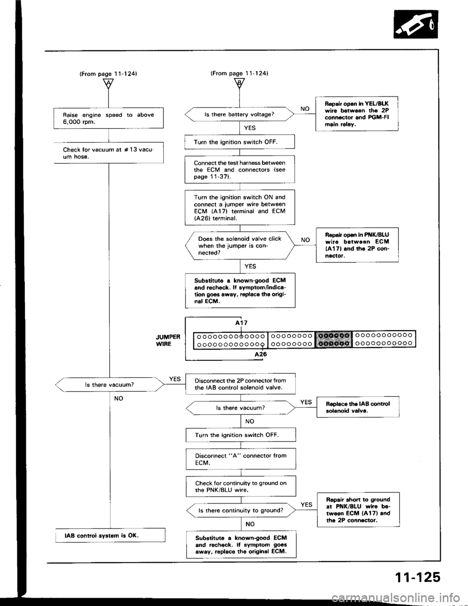
(From page 1 1-124)
Raise engine speed to above6,000 rpm.
Disconnect the 2P connector tromthe IAB control solenoid valve.
Turn the ignition switch OFF.
Check for continuity to ground onthe PNK/BLU wire.
Ropair short to g.ound
at PNK/BLU wiro bo-two6n ECM {A17) andtho 2P connector.
ls there continuity to ground?
Substituto a known-good ECMand racheck. It symptom goos
swsy, roplace tho original ECM.
{From pago 1 1-124}
Repsir op6n in YEL/BLKwiro botwoon tho 2Pconnector and FGM-FImain relaY.
ls there battery voltage?
Turn the ignition swirch OFF.
Connect lhe test harness betweenthe ECM and connectors lseepage 11-37).
Turn the ignition switch ON andconnect a lumper wke betweenECM (A17) terminal and ECM
{A26) terminal.
Ropaiiopon inP K/BLUwiao botwoen ECM
lAl7l and tho 2P con-nectot.
Ooes the solenoid valve clickwhen the jumper is con-nected?
Sub3titute a known-good ECMand rechock. lf symptom/indica-tion goos away, r6place tho origi-nal ECM.
Check lor vacuum at #'l3 vacu-um hose.
IAB control syst6m is OK.
11-125
Page 460 of 1413
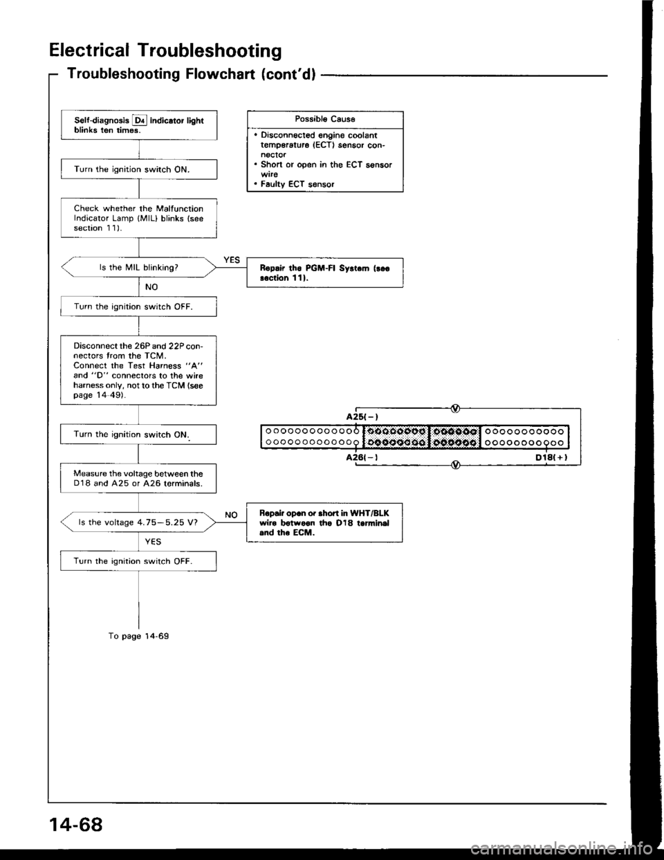
Electrical Troubleshooting
Troubleshooting Flowchart (cont'dl
Possibl€ Caus6
. Disconnoct€d engine coolantt€mp€rature (ECTI sensor con-noctor. Short or open in the ECT sensor
. Faulty ECT s€nsor
Self-diagnosis E indicator lightblinks ten times.
Turn the ignition switch ON.
Check whether the MalfunctionIndicator Lamp {MlL} blinks (seesection 1 1)-
ls the MIL blinking?Rop.ir tho PGM-FI Syrt.m (!go
!.ction 111.
Turn the ignition switch OFF.
Disconnectthe 26P and 22P con-nectors trom the TCM.Connect the Test Harness "A"
and "D" conneclors to the wireharness only, not to the TCM (seepage 14 49).
Measure the voltage between theD'18 and A25 or A26 lorminals.
Bopair op.n or .hofi In WHT/BLKwiro botwoon tho O18 tanni.|al.nd the ECM.ls the voltage 4.75-5.25 V?
Turn the ignition switch OFF.
oooooooooooo
ooooooooooooooooooooooo
oooo o oo o
Dlal + I
Page 1060 of 1413
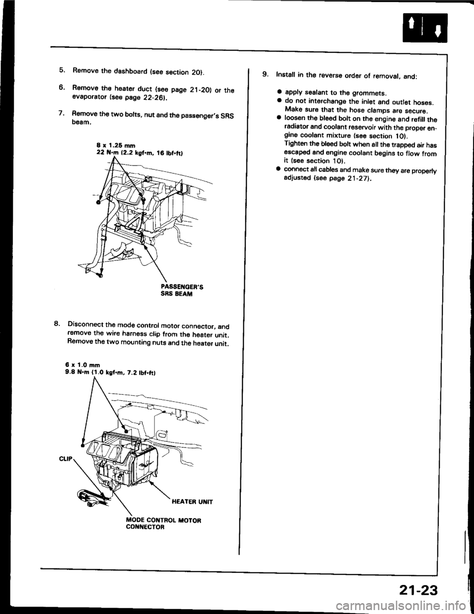
5.
6.
7.
Rsmove the dashboard (see section 2O).
Remove the heater duct (see page 21-20) or theevaporator lse€ page 22-26).
Rsmove the two bolts, nut and the passenger,s SRS(}eam.
PASSEIVGER'SSRS EEAM
Disconnect the mode control motor conngctor, andremove the wire harness clip from the h€8ter unit.Remove the two mounting nuts and the haater unit.
6 r 1.0 mm9.8 .m (l.O kgt.m, 7.2 tbt.frl
MODE COI{TROL I,IOTORcol{t{€cToF
8.
8 x 1,26 mln22 N.m 12.2 kgf.m, 18 tbt.ttl
9. Install in the reverse order of removal, and:
a apply sealant to the grommets.a do not int6rchange the inlet and outl€t hoses.Make sure that the hose clamps are secure.a loosen th€ ble6d bolt on th6 engine and r€fillthetadiator and coolant r€servoir with the propsr en_gine coolant mixture (sse section 1O).Tighten the blsed boh when all the trapped air has6sc8p6d and engine coolant begins to flow fromit (see section 1O).a connect all csbles and make sure they 8re properlyadiusted (see pdge 21-271.
21-23
Page 1107 of 1413

Electrical
Special Tools
Troubleshooting
Tips and Precautions ................................ 23-3Five-stop Tloubleshooting ..............,...-..-... Z3-sSchematic Symbols ................................_. 23-6wire Color Cod€s ..................................... 23-6Relay and Control Unit Locations
Engine Compartment .........,............ ... --. 23-7Dsshboard and Door ..,,......................... 23-gDashboard and Floor ............................. 23-t OOuaner Panel .....-.....23-12Connector ldentification and WireHarness Routing ........ 23-i 3
Index to Circuits and Systems
Airbag ............... ...-..-... 2g-26sAir Conditioning ....,.. Section 2lAltelnator ......_.............. 23-99Anti-lock Brake Systsm (ABS) Section 19Automatic Transmission Section 14Battery .............. .......... 23-66Chafging System ........... 23-98rCigalstte Lighter .....................-...-......-..-.. Z3-2O4Cfock ................. ..........23-197rcruise Controf .......--..-... 23-242Distributor .................... 23-87Fan Controls ................. 23-1ogFuel and Emissions ... Section 1i*Fuses
Under-dash Fuse/Relay Box ................... 23-48Undor-hood ABS Fuse/Retay Box ............ 23-51Under-hood Fuse/Relay Box,.................. 23-52rGauges
Engine Coolant Temperature {ECT)Gauge ................ ..23-126Fuef cauge ............... 2g-123'Gauge Assembly ....--.23-113Speedometer .....-...,,. 23-114Tachometer .....,.....-.. 23-114Ground Distribution ........ 23-60Heater ,,,........,.... ..... Section 2lrHorn ................. ........... 23-199*fgnition Switch ............. 23-70fgnition Syst6m .......-..-.. 23-A7lgnition Timing .............. 23-89Indicator Lights"A/T Gear Position .............. ................... 23-1 32B1ak6 System ...,..,..-.23-127Engine Oil Pressura .............................. _ 23-1 51Low Fuel ............ ......23-125Malfunction Indicator Lamp {MlL} ...,,. Section I l
tfnteglated Control Unit ...29-144*lnterlock System ...................................... 23-1 3gLights, Exteriol
Back-up Lights ........... 23-179Brake Lights .............. 23-t8ltDaytime Running Lights {Csnada} ........... 23-156Front Palking Lights ............................. 23-1 65Flont Side Marker Lights ....................... 23-165Front Turn Signal Lights ........................ 23-1 65*Hazard Warning Lights .........................- 2g-1A4Headlights ................. 23-t6tLicense Plate Lights .............................. 23-1 69Taillights(Harchback) .......... 23-166
{Sedan) .............. .. 23-167Lights. Inteliol
Cargo Area Light {Hatchback) ...... -.. -.. -... 23-177Ceifing Light ........-..-.23-175
Dash Lights Blightness Controt .............. 23-t70Glove Box Lighr ................................... 23-1 69Spotfighr ............ ....-.23-174Trunk Light (Sedanl ............... .............. - 23.-177*Lighting Sysrem .......-.-... 23-152:Moonroof ,,.,.......,..,,,,,.-.23-211PGM-FI Systom ........ S€crion 11Power Distribution .,.-..--..23-54Power Door Locks .............,,..................... 23-233Power Mirors ..,..,....-...- 23-216Power Relays ...........,..... 23-68Power Windows ............ 29-222*Rear Window Defogger ........,... ..........,..... - 23-20,6Reminder Systems
Key-in Remindel System ....,.............,.... 23-1 50Lights-on Reminder System ................... 23-l 5f*Maintenance Reminder system ..,,.... -.. - -. 23-.1 2gSeat Belt Reminder System ..................- 23-125*Side Markel/Turn Signal/Hazard
Ffasher System .,..,..-.23.-1A4Spark Pfugs .........-...-..... 23-97Starting System ....,,.....-. 23-73*Stereo Sound System ...,.......................,,.. 23-l gg
Supplemental Restraint System {SRS} ......... 23-265Vehicfe Speed Sensor {VSS) .............--..-.... 23-122*Wiper/Washer Systom ...............--.........-..- Zg-254
rRead SRS pi€cautions on Page 23-271 betore workingin these areas.
-+
Page 1119 of 1413
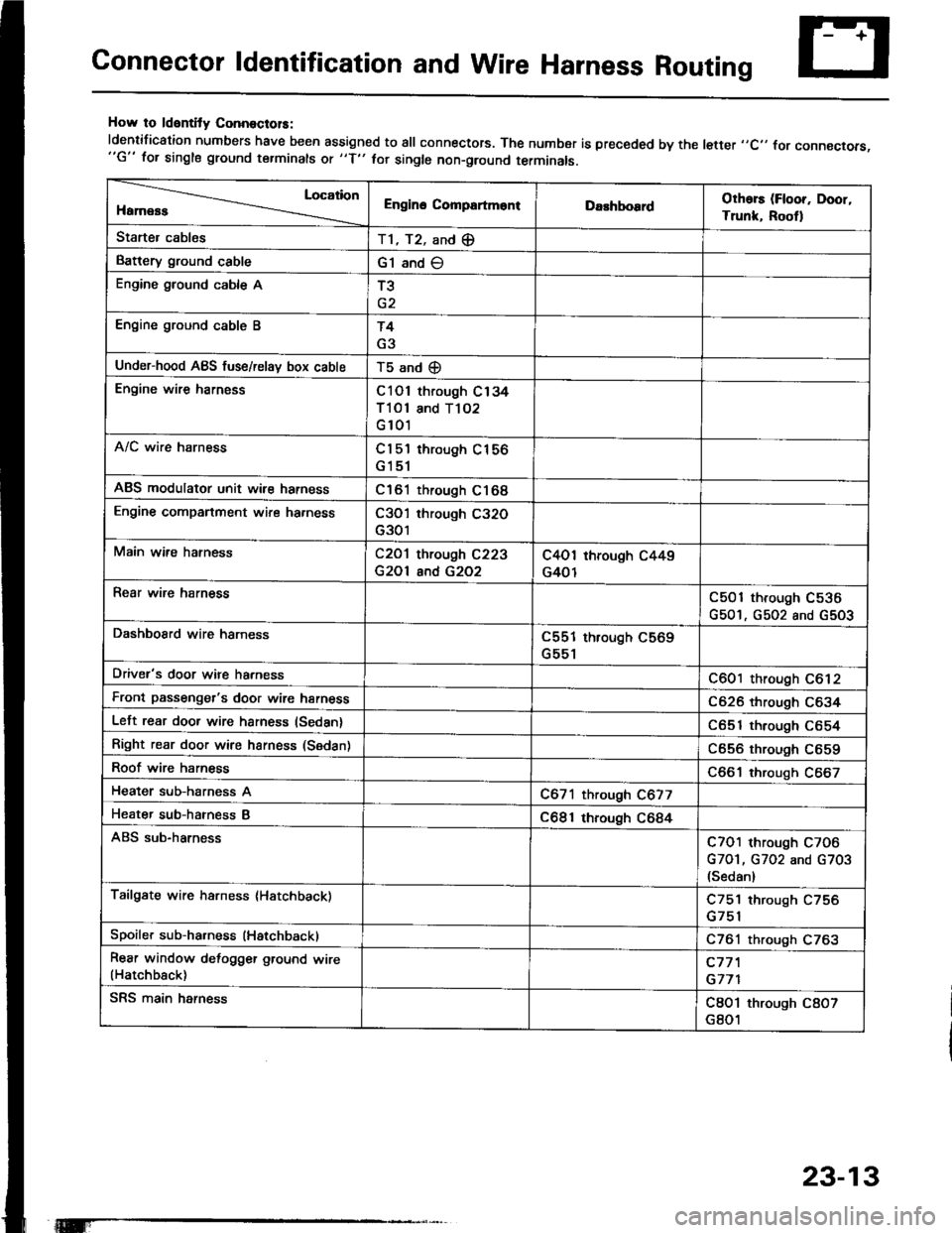
Connector ldentification and Wire Harness Routing
How to ldentity ConnoctolS:
ldentification numbers have been assigned to all connectors. The number is preceded by the letter ,,C,, for connecrors,"G" for single ground terminals ot "f" hr single non-ground terminals.
Location
HamessEngino CompartmontDarhboardOthors (Floor, Door,
Trunk, Rootl
Starter cablesT1, T2, and (E
Battery ground cableG1 and O
Engine ground cable AT3
Engine ground cable BT4
G3
Under-hood ABS fuse/relav box cableT5 and (D
Engine wire harnessC101 through C134
Tl Ol and T102
G 101
A/C wire harnessCl 5'l through C156
G151
ABS modulator unit wir€ harnessC161 through C168
Engine companment wire ha.nessC3O'l through C32O
G301
Main wire hatnessC2O1 through C223
G2Ol and G2O2
C4O1 through C449
G401
Rear wire harnessC501 through C536
G501, G502 and G5O3
DashboSrd wire harnessC551 through C569
G551
Driver's door wire harnessC601 through C612
Front passenger's door wire harnessC626 through C634
Left rear door wire harness (Sedan)C651 through C654
Right rear door wire harness (Sedan)C656 through C659
Roof wire harnessC661 through C667
Heater sub-harness AC671 through C677
Heater sub-hatness BC681 through C684
ABS sub-harnessC7O1 through C7O6
G7O1, G702 and G703(Sedan)
Tailgate wire harness (Hatchback)C751 through C756
Spoiler sub-ha.ness (Hatchback)C761 through C763
Rear window defogger ground wire(Hatchback)c77'l
G771
SRS main harnessC8O1 through C8O7
G801
23-13
Page 1120 of 1413
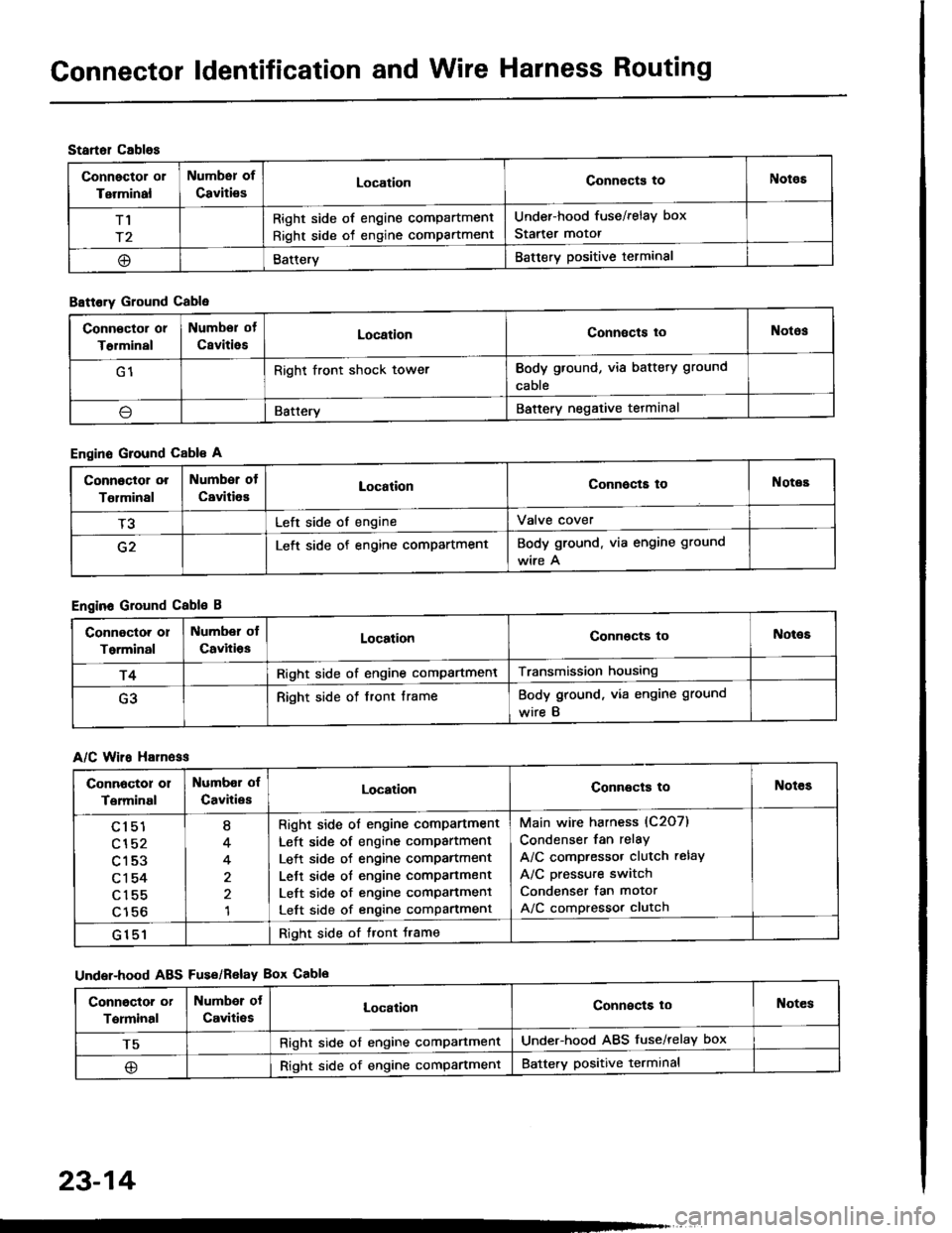
Gonnector ldentification and Wire Harness Routing
Startol cablos
Connector or
Terminal
Numbsr of
CavitiesLocationConnects toNotos
T1
r2
Right side of engine compartment
Right side of engine compartment
Under-hood fuse/relay box
Starter motor
@BatteryBattery positive terminal
B8ttory Ground Cable
Engine Ground Cable A
Engine Ground Cable B
A/C Wiro H81n6ss
Under-hood ABS Fus€/Relav Box Cablo
Conn€ctor or
T€rminal
Numbor of
CsvitiesLocationConnects toNotos
G1Right front shock towerBody ground, via battery ground
cable
\lBatteryBattery negative tetminal
Connoctor or
Tolminal
Number of
CavitiesLocationConnocta toNotes
T3Left side of engineValve cover
G2Left side of engine compartmentBody ground. via engine ground
wire A
Connoctor or
Torminal
Number ol
CavitiosLocationConnocts toNot€s
r4Right side of engine compartmentTransmission housing
G3Right side of front frameBody ground, via engine ground
wire B
Connoctor 01
Terminal
Numbor of
CavitiesLocationConnects toNotes
cl51
cl52
c153
c1 54
c155
c156
I
4
4
1
Right side ol engine comPartment
Left side of engine compartment
Left side of engine comPartment
Lett side ot engine compartment
Left side of engine comPanment
Left side of engine compartment
Main wire harness (C2O7)
Condenser fan relay
A/C compressor clutch relay
A/C pressure switch
Condenser fan motor
A/C compressor clutch
G151Right side of tront Jrame
Conngctor or
Terminal
Numbor ot
Caviti€sLocalionConnects loNotes
T5Right side of engine comPartmentUnder-hood ABS fuse/relay box
@Right side of engine compartmentBattery positive terminal
23-14