injector HONDA INTEGRA 1994 4.G User Guide
[x] Cancel search | Manufacturer: HONDA, Model Year: 1994, Model line: INTEGRA, Model: HONDA INTEGRA 1994 4.GPages: 1413, PDF Size: 37.94 MB
Page 293 of 1413
Fuel Supply System
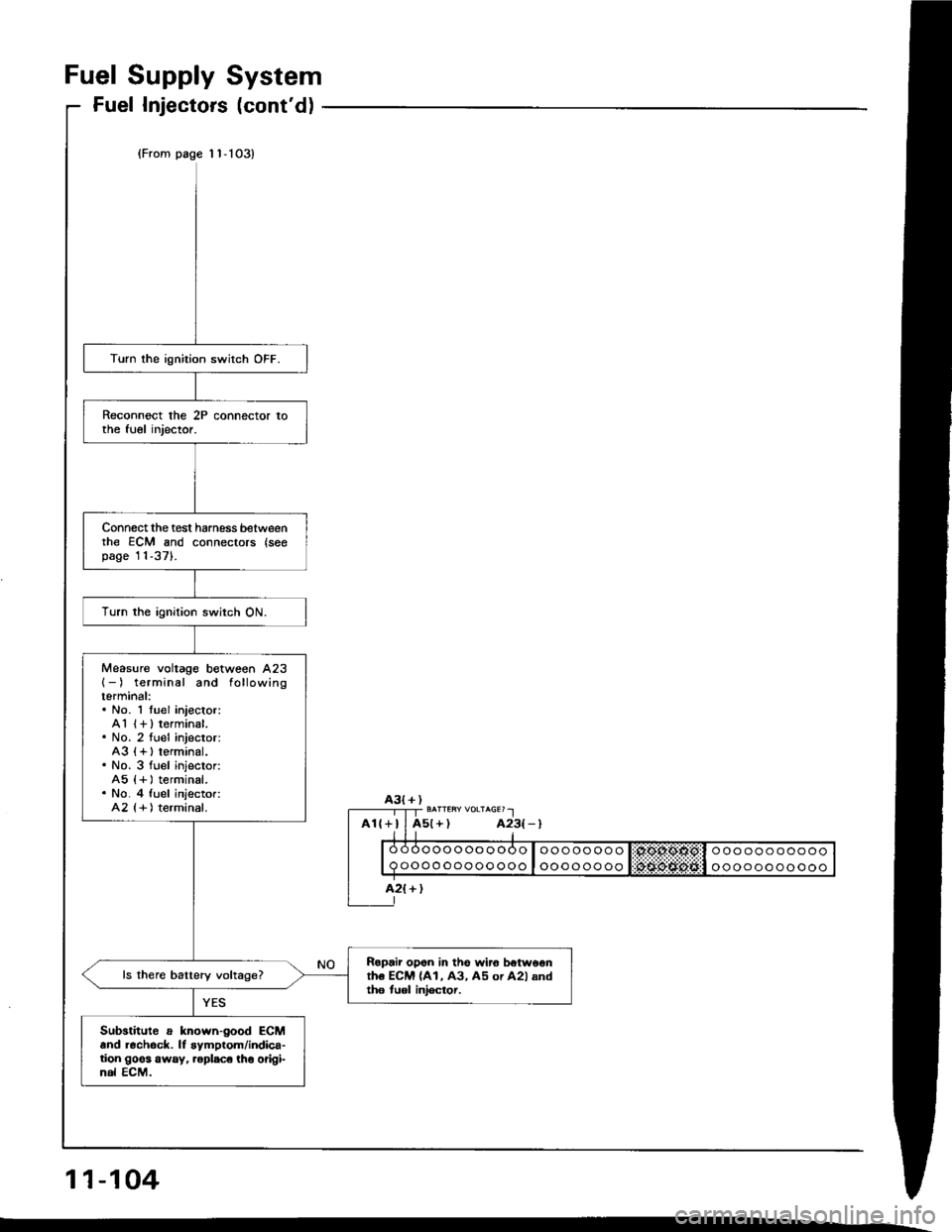
Fuel Injectors (cont'd)
(From page 'l1-103)
Turn lhe ignition switch OFF.
Reconnect the 2P connector tothe tuel injector.
Connect the test harness betweenrhe ECM and connectors {seopage'11-371.
Turn the ignition switch ON.
Measure voltage between A23{-) terminal and followingterminal:. No. 1 tuel injector:A1 (+ ) terminal.. No. 2 fuel injector:A3 {+ I terminal.. No. 3 fuel injector:A5 {+ ) terminal.. No. 4 fuel injector:A2 {+ ) terminal.
Ropair opon in the wi.o betw6onth6 ECM (A1, A3, A5 or A2l andth6 tuel iniector.
Sub3titute a known-good ECMand r6chock. lf symptom/indica-tion goes away, .eplsco tho origi-nal ECM.
oooooooooo
oooooooooooooooooooo
oooooooo
ooooooooooo
ooooooooooo
A3{+)
A2{+}
11-104
Page 294 of 1413
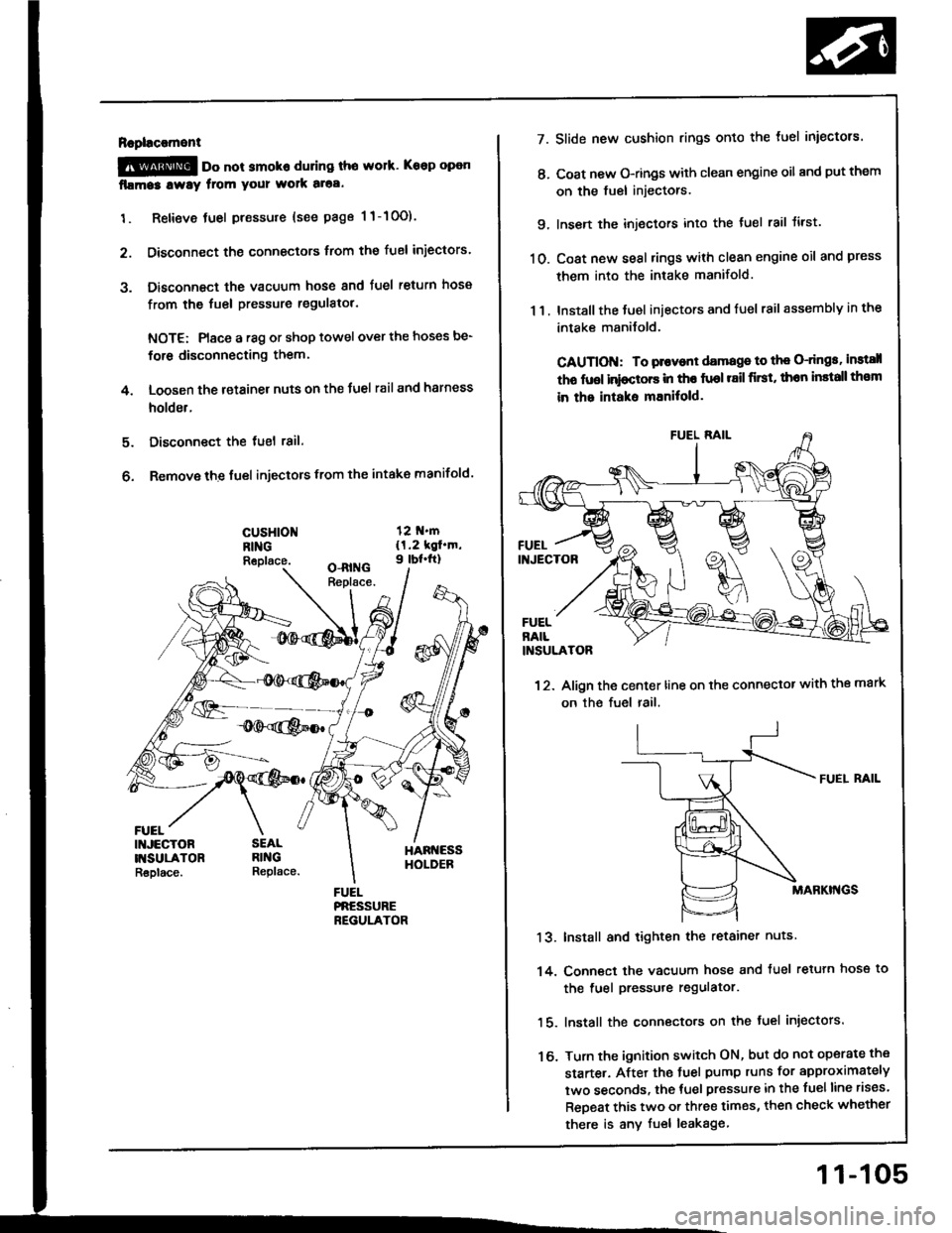
Rapl!c!ment
@ oo not smoko during tho work. Keep open
fllma3 lway from your wolk aloa.
1. Retieve tuel pressure {see page 1 1-10O).
2. Disconnect the connectors trom the fuel iniectors.
3. Disconnect the vacuum hose and fuel return hosa
from the fuel pressure regulatol.
NOTE: Place a r8g or shop towel over the hoses be-
for6 disconnecting them.
4. Loosen the retainer nuts on the Juel rail and harness
holder.
Disconnect the tuel 18il.
Remove the fuel injectors from the intake manifold.
5.
6.
cusHloNRINGReplace.
FUEL
7.
t'.
9.
10.
13.
14.
16.
11.
Slide new cushion rings onto the luel iniectors.
Coat new O-rings with clean engine oil and put them
on the fuel injectors.
Insen the injectors into the tuel rail tirst.
Coat new seal rings with clean engine oil and press
them into the intake manifold.
Install the Juel iniectors and fuel rail assembly in the
intake manilold.
CAUTION: To plovont damage to th€ O-dngs, instsll
tho fuol inioctors in tho fuol r8il first, thon install th€m
in the intaks mEnitold.
12. Align the center line on the connector with the mark
on the fuel rail.
FUEI. RAIL
MABKI'{GS
Install and tighten the retainer nuts
Conn€ct the vacuum hose and tuel retuln hose to
the fuel pressure regulator.
lnstall the connecto.s on the fuel injectors.
Turn the ignition switch ON, but do not operate the
starte.. After the tuel pump runs for approximately
two seconds, the tuel pressure in the fuelline rises.
ReDeat this two or three times, then check whether
there is any fuel leakage
11-105
Page 295 of 1413
Fuel Supply System
Fuel Pressure Regulator
FUELRETURI{
Description
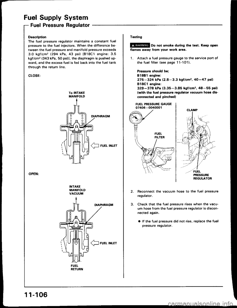
The fuel pressure .egulator maintains a constant Juel
pressure to the tuel injectors. When the difference be-
tween the fuel pressure and manitold pressur€ exceeds
3.O kgf/cm'� 1294 kPa, 43 psi) tB18C1 engine: 3.5
kgt/cm, (343 kPa, 50 psi)], the diaphragm is pushed up-
ward, and the excess fuel is fed back into the fuel tank
through the retufn line,
CLOSE:
DIAPHRAGM
__l FUEL INLET
INTAKEMA'{IFOLDVACUUM
DIAPHNAGM
/1-
\J FUEL INLET
11-106
Te6ting
@ oo not smoko during the t€st. Ko6p opon
flames away from your work area,
1. Attach a fuel pressure gauge to the se.vice port of
the luel filter {see page 11-101).
Prossuro should be;
Bl88l ongin€:
275-324 kPa (2.8-3.3 kgf/cm', 40-47 psil
B18Cl €ngino:
329-378 kPa (3.35-3.85 kgf/cm'�.48-55 pEi)
(with tho tuol pressure rsgulator vacuum hoso dls-
connoctod and pinched)
FUEL PRESSURE GAUGE07406 - oO/IOOO 1
Reconnect the vacuum hose to the fuel pressure
regulator.
Check that the tuel pressure rises when the vacu-
um hose from the fuel pressure regulator is discon-
nected again.
a lf the fuel pressure did not rise, replace the fuel
pressure regulatot.
Page 300 of 1413
PGM-Fl Main Relay
Doscription
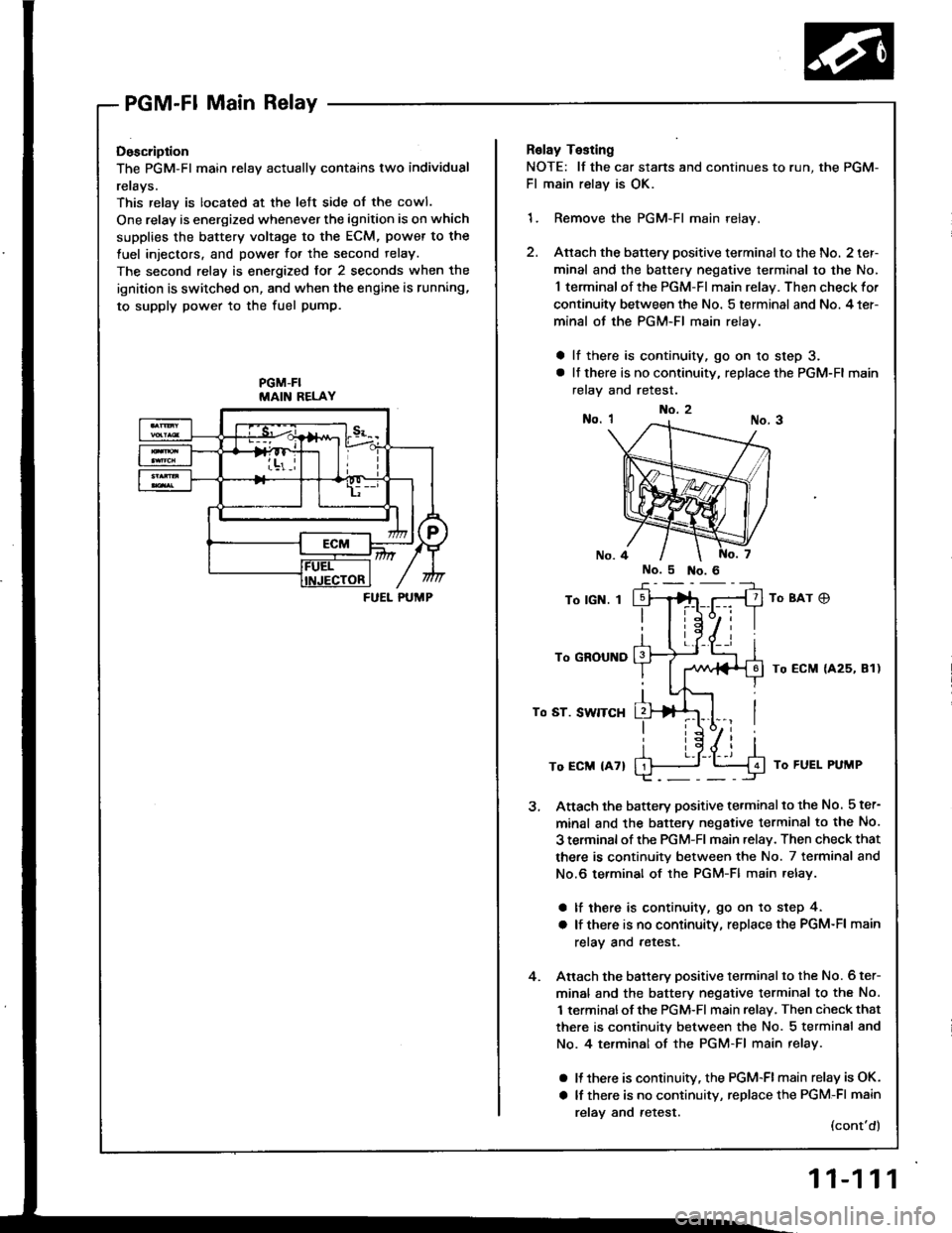
The PGM-Fl main relav actuallv contains two individual
rerays.
This relay is located at the lett side of the cowl.
One relay is energized whenever the ignition is on which
supplies the battery voltage to the ECM, power to the
fuel injectors, and power for the second relay.
The second relay is energized for 2 seconds when the
ignition is switched on, and when the engine is running,
to supply power to the fuel pump.
PGM-FIMAIN RELAY
FUEL PUMP
Relay Testing
NOTE: lf the car stans and continues to r
Fl main relay is OK.
1. Remove the PGM-Fl main relay.
2. Attach the battery positive terminalto
minal and the battery negative termir
1 terminal of the PGM-FI main relay. T
continuity between the No. 5 terminal
minal of the PGM-FI main relay.
a lf there is continuity, go on 10 ste
a lt there is no continuity, replace the
relay and retest.
To lGN. I
To GROUND
To ST. SWITCH
To ECM {47}
Attach the battery positive terminalto
minal and the battery negative termil
3 terminal of rhe PGM-Fl main .elav. Tl
there is continuity between the No. ;
No.6 terminal of the PGM-Fl main re
a lf there is continuity, go on to st€
a lf there is no continuity, replace th€
relay and retest.
Anach the battery positive terminalto
minal and the battery negative termil
1 terminalof the PGM-Fl main relay, Tl
there is continuity between the No. :
No. 4 te.minal of the PGM-Fl main r
a It there is continuitv, the PGM-FI mi
a lf there is no continuity, replace th(
relav and retest.
No.2
run, the PGM-
nalto the No. 2 ter-
terminal to the No.
lay. Then check for
minal and No. 4 ter-
to step 3.
ce the PGM-Fl main
8Ar C)
ECM {425, 81)
J To FUEL PUMP
inalto the No. 5 ter-
terminsl to the No.
ay. Then check that
No. 7 terminal and
ain relay.
to step 4.
ce the PGM-Fl main
inal to the No. 6 ter-
terminal to the No.
ay, Then check that
No. 5 terminal and
nain relay.
-Flmain relay is OK.
ce the PGM-Fl main
(cont'd)
11-111
Page 1122 of 1413
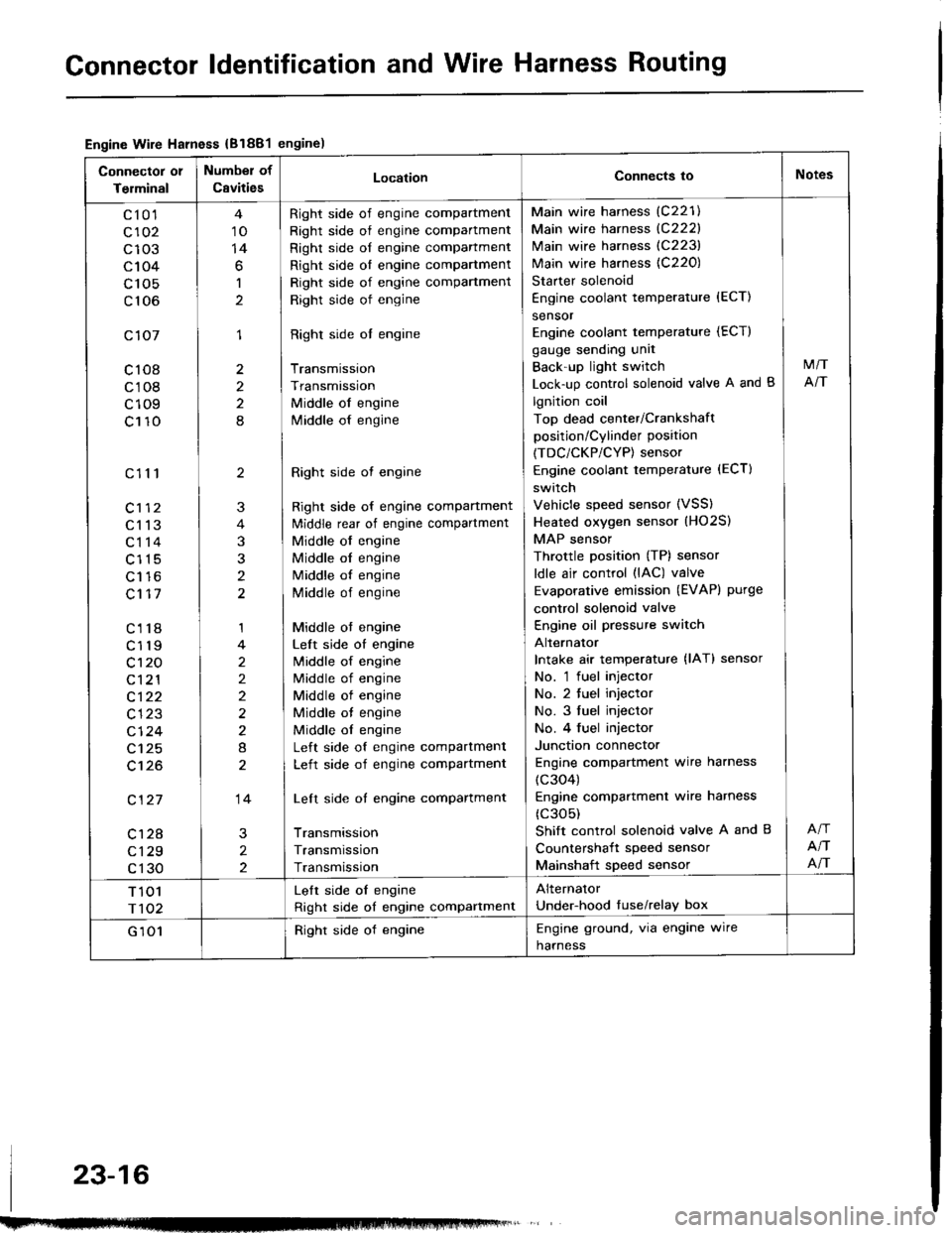
Gonnector ldentification and Wire Harness Routing
Engine Wire Harness {B1881engine)
Connector 01
Terminal
Number of
CavitiesLocationConnects ioNotes
c10'l
c102
c103
c104
c 105
c106
c107
c108
c108
c109
c110
c111
c113
c114
c115
Lt to
c117
c118
c119
c't 20
c121
c122
c123
cl24
c125
c't26
c127
c128
c129
c130
10
14
6
1
1
2
2
8
2
3
t
1
2
2)
2
8
14
2
2
Right side of engine compartment
Right side of engine compartment
Right side of engine compartment
Right side ol engine compartment
Right side of engine compartment
Right side of engine
Right side ol engine
Transmission
Transmission
Middle of engine
lvliddle of engine
Right side ot engine
Right side of engine compartment
ldiddle rear of engine compartment
Middle of engine
Middle ol engine
Middle of engine
Middle of engine
Middle ot engine
Left side of engine
lvliddle of engine
Middle of engine
Middle of engine
Middle ot engine
Middle ol engine
Left side of engine compartment
Left side of engine compartment
Left side of engine compartment
Transmission
Transmission
Transmission
Main wire harness (C221)
Main wire harness {C222}
Main wire harness (C223)
Main wire harness {C220)
Starter solenoid
Engine coolant temperature {ECT)
sensor
Engine coolant temperature (ECT)
gauge sending unit
Back'up light switch
Lock-up control solenoid valve A and B
lgnition coil
Top dead center/Crankshaft
position/Cylinder position
(TDC/CKP/CYP) sensor
Engine coolant temperature (ECT)
switch
Vehicle speed sensor (VSS)
Heated oxygen sensor (HO2S)
MAP sensor
Throttle position (TP) sensor
ldle air control (lAC) valve
Evaporative emission (EVAPI purge
control solenoid valve
Engine oil pressure switch
Alternator
Intake air temperature {lAT} sensor
No. 'l fuel injector
No. 2 tuel injector
No. 3 fuel injector
No. 4 fuel injector
Junction connector
Engine compartment wire harness
(c304)
Engine compartmenl wire harness
(c305)
Shift control solenoid valve A and B
Countershait speed sensor
Mainshaft speed sensor
M/T
NT
NT
NT
T 101
r102
Lelt side oI engine
Right side of engine compartment
Alternator
Under-hood tuse/relay box
G 101Right side of engineEngine ground, via engine wire
harness
23-16
Page 1124 of 1413
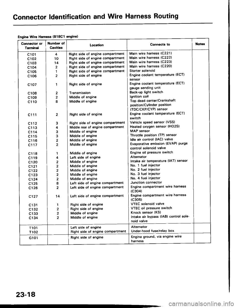
Gonnector ldentification and Wire Harness Routing
Engine Wire Harnoss (B18Cl enginol
Connoctor 01
Totminal
umbor ol
Cavitio8LocationConnecla tof{orc!
c 101
cl 02
c103
c104
c105
c106
c107
c108
c109
c110
c111
cl12
c113
c114
c115
c116
c117
c1r8
c119
c120
cl2'l
c122
c123
c124
c125
c't26
c'127
c 131
c132
c133
c134
2
J
4
3
'I
4
2
I
2
't4
1
4
10
14
,l
2
2
8
Right side of engine compartment
Right side of engine compartment
Right side ot engine comPanment
Right side of engine compartmsnt
Right side of engine compartment
Righr side ot engine
Right side of engine
Transmission
Middle ol engine
Middle oJ engine
Right side of engine
Right side ot engine comPartment
Middl€ reat of engine compartment
Middle of engine
Middle of engine
Middle ol engine
Middle o{ engine
Middle of engine
Lelt side ot engine
Middle of engine
Middle of engine
Middle ol engine
Middle ot engine
Middle of engine
Left side of engine companment
Lelt side ot engine compartment
Left side of engine compartment
Right side ot engine
Right sid€ of engine
Middle ot engine
Middle of engine
Main wire harness (C221)
Main wire harness (C222)
Main wire harness (C223)
Main wire harness (C22O)
Starter solenoid
Engine coolant temperature (ECT)
sensor
Engine coolant temperature {ECTI
gauge sending unit
Back-up light switch
lgnition coil
Top dead center/Crankshaft
position/Cylind€r Position(TDC/CKP/CYP) sensor
Engine coolant temperature {ECT)
switch
Vehicle speed sensor (VSS)
Hsated oxygen sensor {HO2S}
MAP sensor
Throttle position {TPl sensor
ldle air control (lAC) valve
Evaporative emission {EVAPI purge
control solenoid valve
Engine oil pressure switch
Alt€rnatot
Intake 8ir temperature (lAT) ssnsor
No. 1 fuel injector
No. 2 fuel iniector
No. 3 fuel injeclor
No. 4 fuel injector
Junction connector
Engine compartment ware harness
{c304)
Engine comPanment wire harness
(c305)
VTEC solenoid valve
VTEC oil pressure switch
Knock sensor (KS)
Intaka air bypass (lAB) control sole-
noid valve
T101
r102
Left side of engine
Right sid6 ot engine compartment
Alternator
Under-hood fuse/relay box
G 101Right side of engineEngine ground, via engine wire
harness
23-18