open hood HONDA INTEGRA 1994 4.G Workshop Manual
[x] Cancel search | Manufacturer: HONDA, Model Year: 1994, Model line: INTEGRA, Model: HONDA INTEGRA 1994 4.GPages: 1413, PDF Size: 37.94 MB
Page 235 of 1413
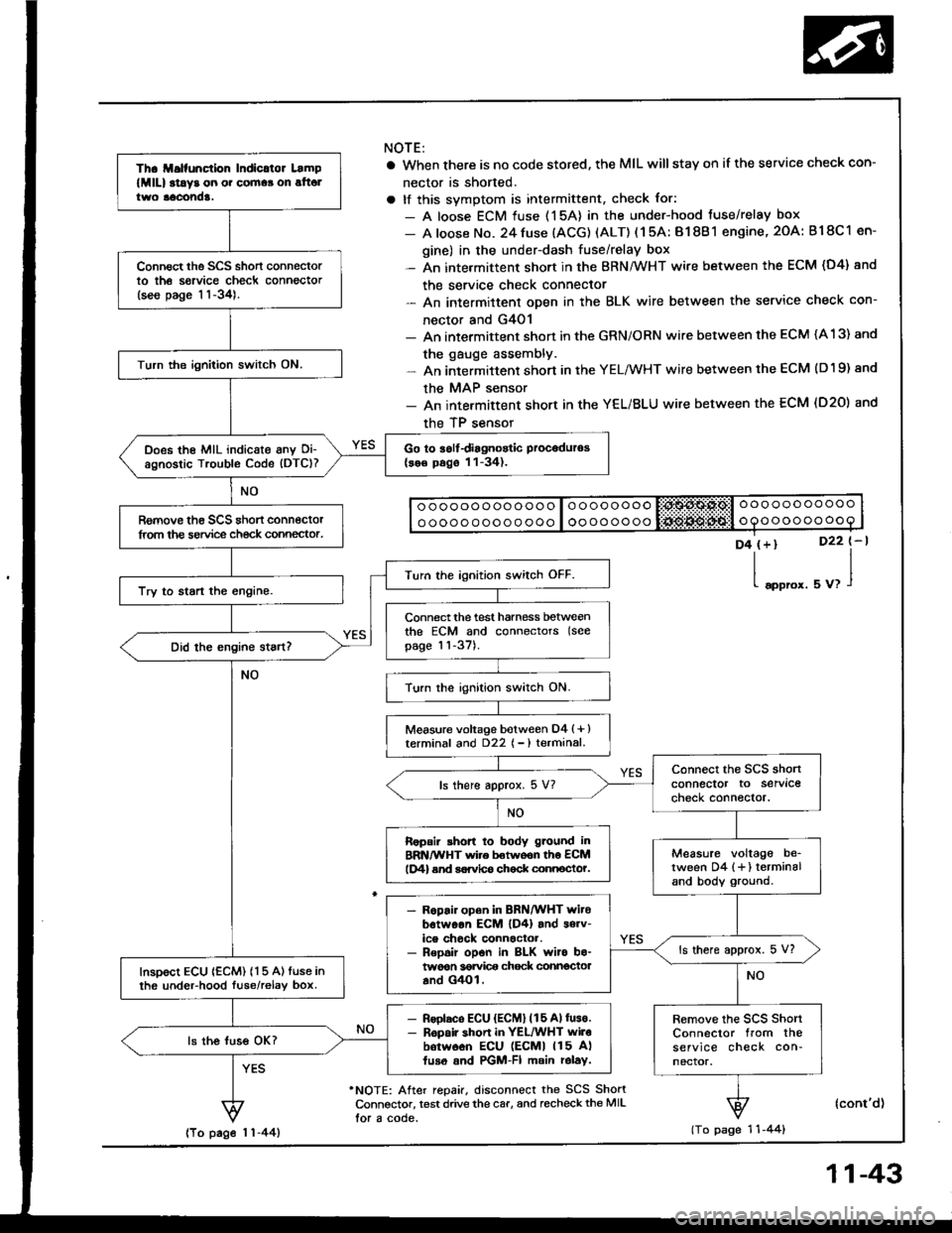
Th. ll.lfunction Indicltor Lamp
lMlll at!y3 on o. cornaa on alt6ltwo aacond!.
Connect the SCS short connectorto th6 sorvice check connector(see page 11-34).
Turn the ignition switch ON.
Go to iolfdiagnostic Proceduros(se€ pago 11-34).Does the MIL indicate anv Oi-agnostic Trouble Code (DTC)?
Romove th€ SCS shon connectorlrom the service ch€ck connector.
Turn the ignition switch OFF.
Try to start the engine.
Connect the test harness betweenthe ECM and connectors (see
page 11-37).
Turn the ignition switch ON.
Measure voltage botween D4 (+ )terminal and D22 { - ) terminal.
connect the SCS shonconnector to servlcecheck connector.ls there approx. 5 V?
Ropair shon to body g.ound inBRN/WHT wire betwoon th6 ECMlD4) end sorvlco chock connocto?.Measure voltage be_tween D4 {+} terminaland body ground.
- R6pair open in BRN/WHT witobotwoon EcM lD4) and s6rv-ice chock connactor.- Repoir opon in BLK wiro bo-twoon 36rvi@ chock connectoaand G4Ol.
ls there approx. 5 V?
InsDoct ECU {ECM) 115 A) tuse inth6 undeFhood luse/relav box.
- Rsolaco ECU {ECM} (15 Allus€.- R6pair shon in YEL/WHT wilobotw6on ECU lEcMl 115 A)fuso and PGM-FI main rolay.
Remove the scs shortConnector from theservice check con-nector.
ls the luss OK?
NOTE:
a When there is no code stored, the MIL willstay on if the service check con-
nector is shorted.
a tf this svmotom is intermittent, check for:
- A loose ECM fuse (15A) in the under-hood tuse/relay box
- A loose No. 24 fuse (ACG) (ALT) ( 1 5A: B1 8B 1 engine, 2OA: B18C 1 en-
gine) in the under-dash fuse/relay box- An intermittent short in the BRN/WHT wire between the ECM (D4) and
the service check connector- An intermittent oDen in the BLK wire between the service check con-
nector and G4O1- An intermittent shon in the GRN/ORN wire between the ECM (A 13) and
the gauge assembly.- An intermittent short in the YELMHT wire between the ECM (D19) and
the MAP sensor- An intermittent short in the YEL/BLU wire between the ECM (D20) and
the TP sensor
o ooooo ooo ooo o loooooooo liii:$A$.Ps,l o oo ooo ooooo
o oooo ooo o o ooo I oooooooooooooooooo
D4 (+)
l"oo,o'.
D22 t-l
uu,l
'NOTE: After repair, disconnect the SCS ShortConnsctor, test drive the car, and recheckthe MIL
lor a code.
(cont'd)
(To page 1 'l -44)lTo page 1 1-44)
11-43
Page 301 of 1413
![HONDA INTEGRA 1994 4.G Workshop Manual Fuel Supply System
PGM-Fl Main Relay (contdl
BLU
BLU/wHt
Bt-xNOTE:. M/T: Clutch pedal mustbe depressed.. A/T: Transmission in
N or E] position.
BLK/ YEL/YEL BLK
Tloubloshooting
{To page 11 113}
- Eng HONDA INTEGRA 1994 4.G Workshop Manual Fuel Supply System
PGM-Fl Main Relay (contdl
BLU
BLU/wHt
Bt-xNOTE:. M/T: Clutch pedal mustbe depressed.. A/T: Transmission in
N or E] position.
BLK/ YEL/YEL BLK
Tloubloshooting
{To page 11 113}
- Eng](/img/13/6067/w960_6067-300.png)
Fuel Supply System
PGM-Fl Main Relay (cont'dl
BLU
BLU/wHt
Bt-xNOTE:. M/T: Clutch pedal mustbe depressed.. A/T: Transmission in
N or E] position.
BLK/ YEL/YEL BLK
Tloubloshooting
{To page 11 113}
- Engino will not sran.- Inspection oI PGM-FI main re-lay and rolay ha.n6!a.
Check lor continuitv between BLKterminal @ and body ground.
Rapair open in BLK wire botwoonPGM-FI main.el6y and GIO'l llo-catod at thormostot housingl.
Measure the voltage betweenYELMHT terminal @ and bodyground.- Roplaco th. ECU IECMI(15 Allus6 in tho under-hood fu!o/r6-lay box.- Ropair opan or short in theYEL/WHT wil6 botwosn thePGM-FI main rolay and the ECU
{EcMl 115 A} luso.
ls there battery voltage?
Turn the ignition switch ON.
Measure the voltage betweenBLK/YEL terminal @ and bodyground.- Reolac. ths No. 24 ACG {ALT}{lcl {15 A:81881 6ngino, 20A: Bl8Cl engin6) tuse in thoundor-dash fuso/rolaY box.- Ropaii op6n or rhon in thoBLK/YEL wiro botwoen thoPGM-FI main ielay and th€ No.24 ACG {ALT) flG} {'�15 A:818Bi ongine, 20 A: 818Cionginol fuso.Turn the ignition switch to theSTART position.
Measure the voltage betweenBLUMHT terminsl @ and bodyground.
- Replaco the l\lo. 18 STARTERSIGNAL {7.5 A} fuso in thoundor-dash fuaa/rolay box.- R6pai. open or short in thoBLU/WHT wire botweon thsPGM-FI main relay and tho No.1A STARTER SIGNAL I7.5 AIluse.
11-112
Page 443 of 1413
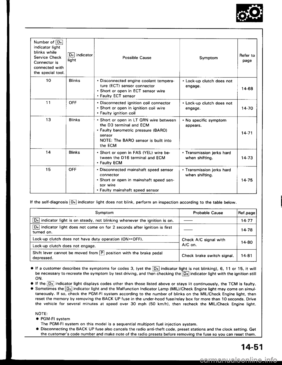
Number of @indicator light
blinks while
Service Check
Connector is
connected with
the special tool.
@ indicator
lightPossible CauseSymptomRefer to
page
'loBlinksDisconnected engine coolant tempera-
rure (ECT) sensor connector
Short or open in ECT sensor wire
Faulty ECT sensor
Lock-up clutch does not
engage.14-68
1lOFFDisconnected ignition coil connector
Short or open in ignition coil wire
Faulty ignition coil
. Lock-up clutch does not
engage.'t 4-7 0
13Blinks. Shon or open in LT GRN wire between
the D3 terminal and ECM. Faulty barometric pressure {BARO)
sensor
NOTE: The BARO sensor is built into
the ECM
. No specific symptom
appears.
14-7 1
14Blinks. Short of open in FAS {YEL} wire be-
tween the D16 terminal and ECM. Faulty ECM
. Transmission jerks hard
when shitting.
't5OFFDisconnected mainshaft speed sensor
connecror
Short or open in mainshaft speed sen-
sor wire
Faulty mainshaft speed sensor
. Transmission jerks hard
when shifting.
14-75
SymptomProbable CauseRet.page
LQ! indicator light is on steady, not blinking whenever the ignition is on.14-77
[Q3] indicator light does not come on for 2 seconds after ignition is first
turned on.14-78
Lock-up clutch does not have duty operation (ON-OFFI.Check A/C signal with
A/C on.14-80Lock-up clutch does not engage.
Shitt leve. cannot be moved lrom @ position with the brake pedal
depressed.Check brake switch signal,14-41
It the self-diagnosis LQ4 indicator light does not blink, perform an inspection according to the table below.
a lf a customer describes the symptoms for codes 3, (yet the LQ! indicator light is not blinkingl, 6, 1 1 or 15, it will
be necessa.y to recreate the symptom by test driving. and then checking the @ indicator light with the ignition still
oN.
e lt ttre @ indicator light displays codes olher than those listed above or stays lit continuously, the TCM is faulty.. Sometimes the Lqd indicator light and the Malfunction Indicator Lamp (MlL)/Check Engine light may come on simul-taneously. lf so, check the PGM-Fl system according to the numbe. of blinks on the MIL/Check Engine light. thenreset the memory by removing the BACK UP fuse in the unde.-hood fuse/relay box for more than 1O seconds. Drive
the vehicle for several minutes at speed over 30 mph (5O km/h), then recheck the MIL/Check Engine light.
NOTE:
. PGM-FI system
The PGM-Fl system on this model is a sequential multiport fuel injection system.a Disconnecting the BACK UP luse also cancels the radio anti-theft code. preset stations and the clock setting. Get
the fuse so vou can reset them.the customer's code number and make note ot the radio
14-51
Page 470 of 1413
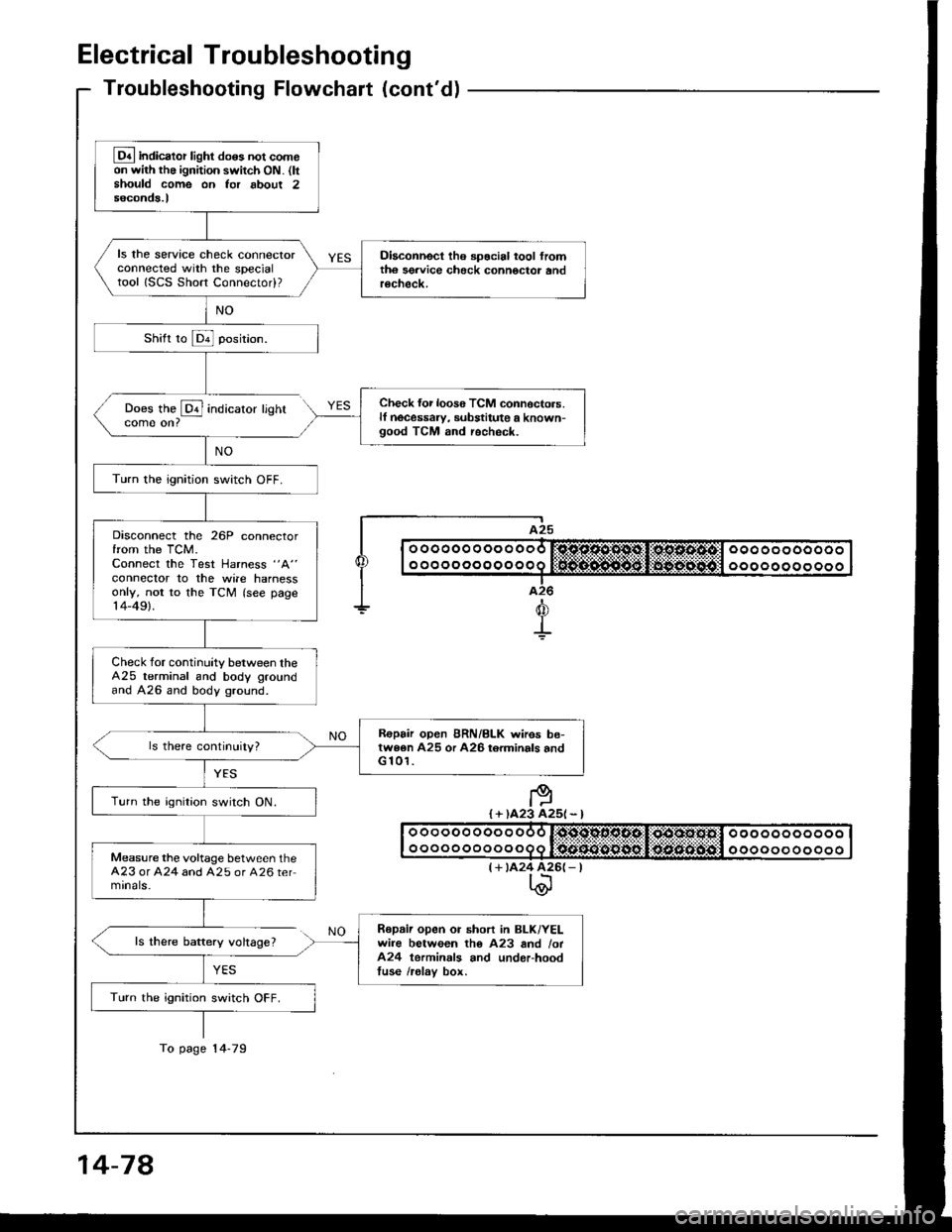
Electrical Troubleshooting
Troubleshooting Flowchaft (cont'dl
Does the @ indicatorcome on?
ls there baftery voltage?
YES
lighr
I A25
| | o ooooo o oo o ooo r:sjc.o.sl'1*st,li*os.s.4tcl ooo oo oooooo I
I I o o o o o o o o o o o o q lifrif.S..n${5git:li$gg-:aiiigitll o o o o o o o o o o o I|--.-T..-I a26
+d
+
I + )A23 A25l - l
(+ tA24 426(- |t\@
Lq4 indicator light do6s not comeon with the ignition switch ON. (ltshould come on Ior about 2seconds.l
ls the service check connectorconnected with the specialtool ISCS Short Connectod?
Diaconnect tho spocial tool fromth6 sgrvice check connoctor andrecheck.
Check {or loos6 TCM connoctors.lf necessaw, substitute a known-good TCM and recheck.
Turn the ignition switch OFF.
Disconnect the 26P connectorfrom the TCM.Connect the Test Harness "A"
conneclor to the wile harnessonly, not to the TCM (see page14-49).
Check for continuity between theA25 terminal and body groundand A26 and body ground.
R€pair open BRN/BLK wires be-twe6n A25 or A26 torminals andG 101.
Turn the ignition switch ON.
Measure the voltage between theA23 or A24 and A25 or A26 termrnals-
Repaii open or short in BLK/YELwire between tho A23 and /ot424 terminals and underhoodtuse /relav box.
Turn the ignition switch OFF.
To page 14-79
14-78
Page 960 of 1413
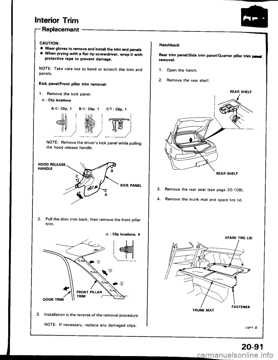
Interior Trim
Replacement
a W€al gloves to remove and installth€ trim and panols.a When prying with a flat tip screwd.ivor. wrap it withprotective tap€ to prevent damaga.
NOTE: Take care not to bend or scratch the trim andDanels.
Kick panel/Front pillar trim removal:
l. Remove the kick Danel.
< : Clip locations
A< | Cllp, 1 B< : Ctip, 1 CV : C[p, 1
Jtl,Ml*
U ry-ry
NOTE: Remove the driver's kick panel while pullingthe hood release handle.
KICK PANEL
Pull the door trim back, then remove the front oillarrflm.
< : Clip locations, 4
lnstallation is the reverse of the removal procedure.
NOTE: lf necessary, .eplace any damaged clips.
FRONT PILLAR
20-91
Hatchback
Rear trim panet/Side trim panel/Ouarter pillar trim p-l16moval:
1. Open the hatch.
2. Remove the .ear shelt.
Remove the rear seat (see page 20-'l08).
Remove the trunk mat and spare tire lid.4.
ao..t dr
REAR SHELF
REAR SHELF
TRUNK MAT
SPARE TIRE LID
Page 1008 of 1413
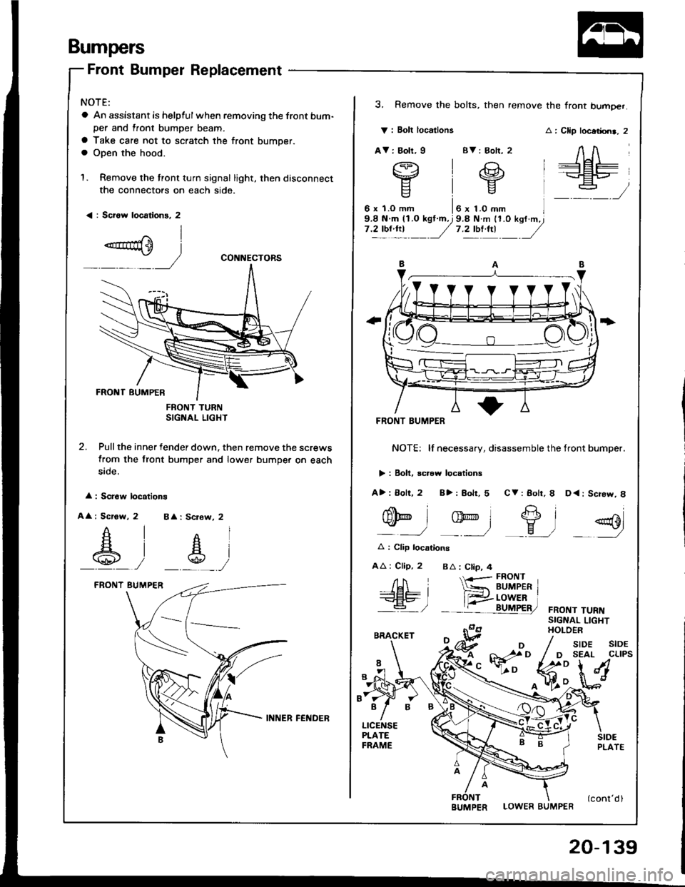
Bumpers
Front Bumper Replacement
NOTE:
a An assistant is helpful when removing the front bum-per and lront bumper beam.
a Take care not to scratch the front bumper.a Open the hood.
1. Remove the tront turn signal light, then disconnect
the connectors on each side.
< : Sci6w locatlons, 2
FNONT TURNSIGNAL LIGHT
2. Pull the inner fender down. then remove the screws
from the front bumper and lower bumper on each
5rcte.
: Scr6w locations
A : Scrow, 2 BA: Scrow, 2
_A_, __s_,
CONNECTORS
V : Bolt locations
AV: Boh, I BV: Bolr, 2
3. Remove the bolts, then remove the front bumoer.
: Clip locadrn., 2
AA
+Et=-+EP_
:
FRONT BUMPER
NOTE: lf necessary, disassemble the tront bumper.
> : Boll, screw locations
A>: 8olt, 2 8>: Bolr, 5 CV: Bolr, I D<: Screw, 8
nolt
gD
Et2"'l-eo
q-l -ry-l _9, =g
A : Clip locarions
AA : Clip, 2 BA : Ctip, 4
FRONT TURNSIGNAL LIGHTHOLOER
/H i-<€L9- I'a- /
{-r-- FRONT
*= BUMPER r
__tr:i!uF&,
LOWER BUMPER
/ sroe stoE
/ D SEAL CLIPS
fr:**M
INNER FEl{DER
BUMPER
20-139
Page 1013 of 1413
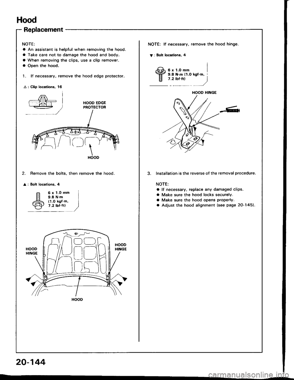
Hood
Replacement
NOTE:
a An assistant is helplul when removing the hood.
a Take care not to damage the hood and body.
a When removing the clips, use a clip remover.
a Open the hood.
1. It necessary, remove the hood edge protector.
: Clip loc.tions, 16
NOTE: It necessary, remove the hood hinge.
V : Boh locationa, 4
I3;;,iH"-,,., I
j .rtor"t
- )
HOOD EDGEPROTECTOR
\HOOD
2. Remove the bolts. then remove the hood.
: Bolt localions, 4
lnstallStion is the reverse of the removal procedure.
NOTE:
a lf necessary, replace any damaged clips.
a Make su.e the hood locks securely.
a Make sure the hood opens properly.
a Adjust the hood alignment (see page 20-1451.
6x1.0mm9.8 N'm{l.O kgl m,7.2 lbl.fr)
HOOD HINGE
n
r)
HOOD
20-144
Page 1021 of 1413
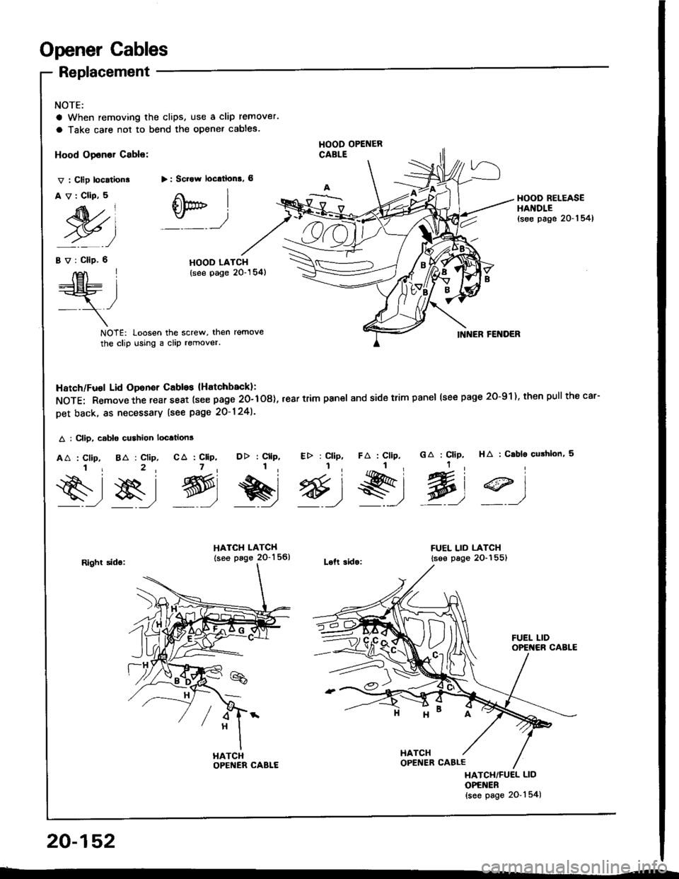
Opener Cables
NOTE:
a When removing the clips, use a clip remover.
a Take care not to bend the opener cables.
Replacement
Hood Opener Cable:
v : Clip location.
Av:CllP,5
M)
HOOD OPENERCABLE
> : Scrow locrtions, 6
Otr" I
:_ _)
HOOD RELEASEHAI{DLE(se€ page 20-1 54)
Bv:Clip.6HOOD LATCH(see page 20"154)E\I____lEt- L:=r
,/- -\-
NOTE: Loosen the screw, then remove
the clip using a clip remover.INNER FENDER
HA : C.bl6 cushlon, 5GA : Clip,
Wt
DD : Cllp, Etr : Cllp,1, I,
e&r @)9)
HATCH LATCH
lsee page 2O-1 56)Loft 3ido:
FUEL LID LATCH
lsse page 2O-155)
Hatch/Fuol Lid Oponer Cabls lHatchback):
NOTE: Remove the rear seat (see page 20-108), rear trim pan€l and side trim panel (see page 2O-91), then pull thecar-
Det back. as necessary lsee page 20-124).
A : Clip, csblo cushion location3
AA : Clip, 8A : Clip, CA : CliP,i r 2, 7,
s-,$, g,
FA : Cllp,
s,l
Right sids:
HATCHOPENER CABLE
HATCH/FUEL LID
OPENER{see page 2O-'l 54)
20-152
HATCH
Page 1022 of 1413
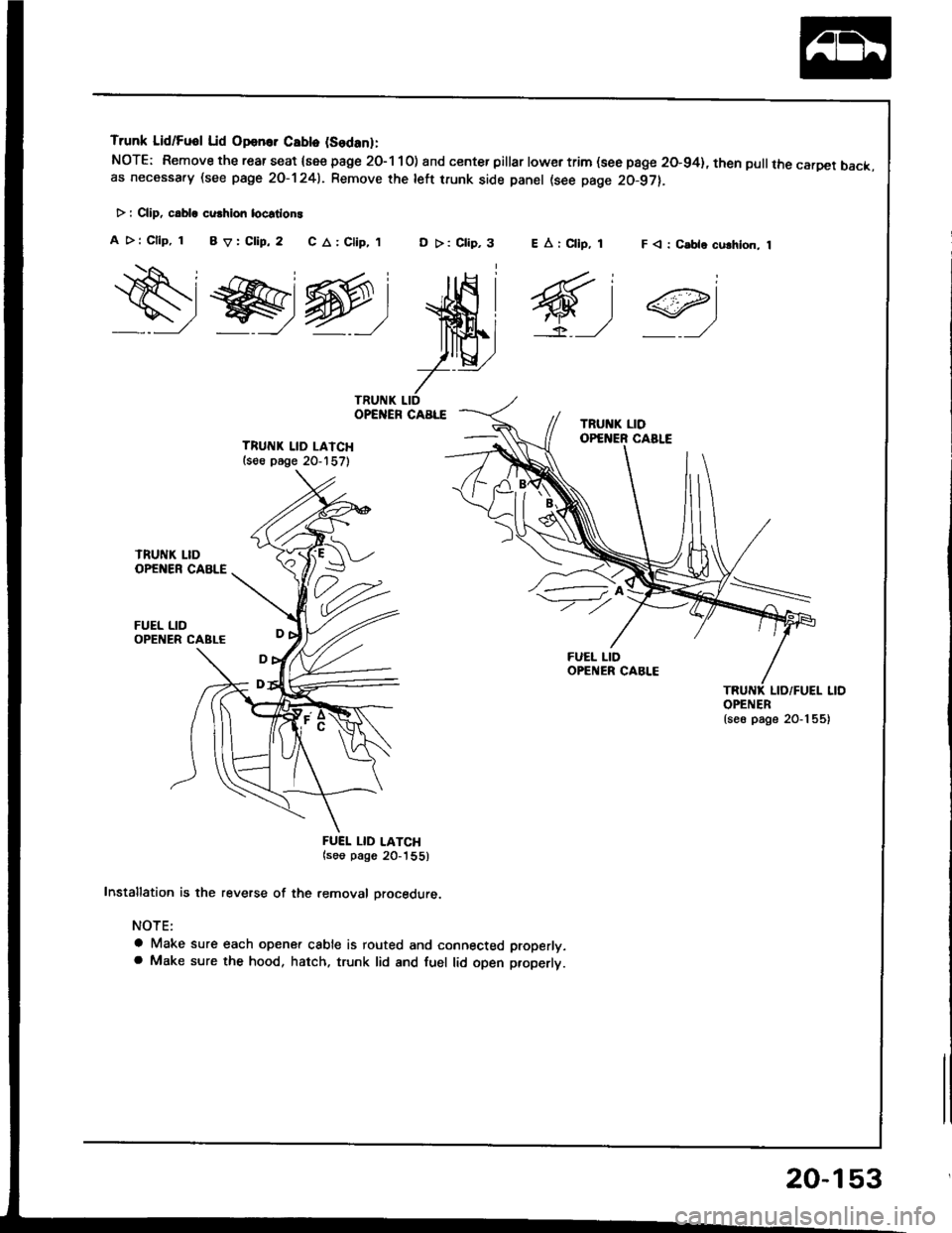
Trunk Lid/Fuol Lid Opan.. Cablo (Sodanl:
NOTE: Remove the rear seat {see page 2O-1 10) and center pillar lowertrim (see page 20-94}, then pullthe carDet back.as necessa.y (see page 2O-1241. Remove rhe left trunk side panel (see page 20-97).
> : CliD, c.bla cu.hion locstlon!
A >: Cllp, 1 BV:Clip,2 C A: Clip,,tD >: Clip,3F < : C.ble culhlon, 1
ws@:
ffi;
7--
TRUITIK LID LAICH(s€e p6ge 20-157)
FUEL LID
FUEI. LID LATCH(soo pago 20_'|55)
Installation is the reverse of the removal orocedure.
NOTE:
a Make sure each opener cable is routed and connected properly.a Make sure the hood, hatch. trunk lid and fuel lid open properlt.
EArCllp, 1
6,1
OPENER{se6 page 20-1 55)
20-153
Page 1023 of 1413
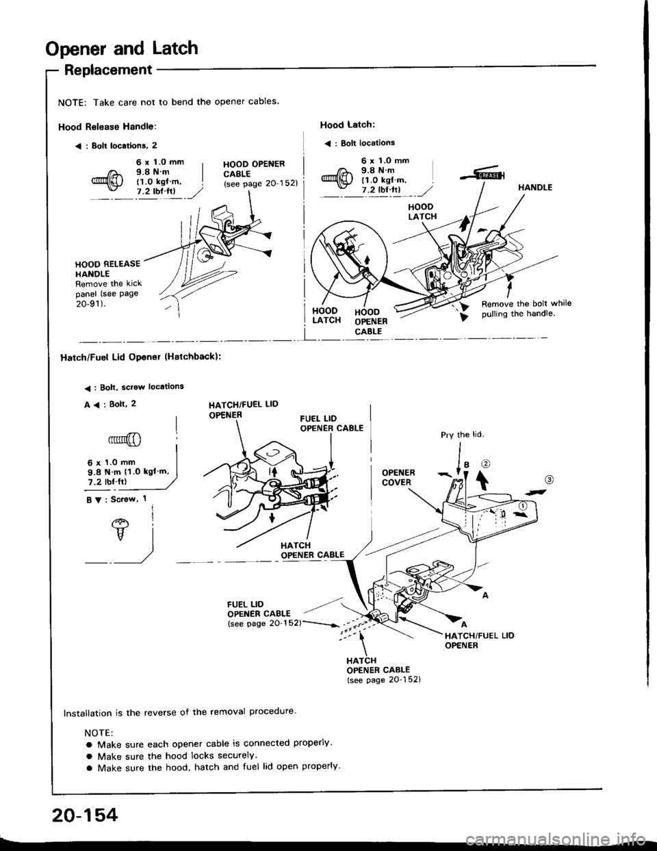
Opener and Latch
Replacement
NOTE: Take care not to bend the opener cables.
Hood Relsase Handle:
< i Bolt locations, 2
Hood Latch:
< : Bolt locations
6 x 1.0 mm9.8Nm(1.0 kgl m,7.2 tbl.lrl
HOOD OPENERCABLE(see page 20'152)
6 x 'l.O mm9.8Nm11.0 kgl m,7 .2 tbt ftl,/HANDLE
HOODLATCH
HOOD RELEASEHANOLERemove the kickpanel (see page
20-91).HOODLATCHHOODOPENERCABLE
Remove the bolt whilepulling the handle.
I
Hatch/Fuel Lid Opener lHatchback):
< : Bolt, sclow locations
A
6' I
vl
/
HATCHiFUEL LID
OPENER
6 x 1.0 mm
9.8 N m 11.0 kgl'm,
7.2 tbl.fr)
FUEL LIDOPENER CAELE
lnstallation is the reverse of the removal procedure'
NOTE:
a Make sure each opener cable is connected properly
a Make sure the hood locks securely
a Make sure the hood, hatch and fuel lid open properly.
the
J'o
t
OPENERCOVER
HATCHOPENER CABLE(see page 20-152)
@
t-
20-154