low oil pressure HONDA INTEGRA 1994 4.G User Guide
[x] Cancel search | Manufacturer: HONDA, Model Year: 1994, Model line: INTEGRA, Model: HONDA INTEGRA 1994 4.GPages: 1413, PDF Size: 37.94 MB
Page 417 of 1413
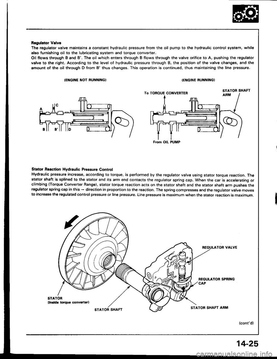
Rcgulator Valve
The r€gulator valve maintains a constant hydraulic pressure from the oil pump to the hydraulic control system, whil€
alEo furnishing oil to the lubricating system and torque convener.
Oil flows through B and B'. The oil which enters through B flows thfough the valve orifice to A, pushing the regulator
valve to the right. Acco.ding to the level of hydraulic pressure through B, the position of the valve changes, and the
amount of the oil thlough D from B'thus changes. This operation is continued. thus maintaining the line pressure.
IEI{GINE ]IIOT RUNNINGI{ENGINE RUNNING)
Siator Reaction Hydtaulic Pressure Control
Hydraulic pressure increase, according to torque, is performed by the regulator vslve using stator torque reaction. Thestator shaft is splined to the stator and its a.m end contacts the fegulator spring cap. When the car is accelerating orclimbing (Torque Convener Range). stator torque reaction acts on the stator shalt and the stator shaft arm pushes thersgulator spring cap in this - direction in proportion to the reaction. The spring compresses and the regulator valve movesto increase the regulated control pressure or line pressure. Line pressure is maximum when the stator reaction is maximum.
TOR VALVE
(cont'd)
From OIL PUMP
STATOR SHAFTSTATOR SHAFT ARM
14-25
Page 420 of 1413
![HONDA INTEGRA 1994 4.G User Guide Description
Genelal Chart ol Hydraulic Pressure
Hydraulic Flow
. Regulator Valve
. Manual Valve
. Modulator Valve
. 1-2 Shilt Valve l. 2-3 Shitt Valve. 3 4 Shift Vlave ]
. Throttle Valve B
Oil Pump - HONDA INTEGRA 1994 4.G User Guide Description
Genelal Chart ol Hydraulic Pressure
Hydraulic Flow
. Regulator Valve
. Manual Valve
. Modulator Valve
. 1-2 Shilt Valve l. 2-3 Shitt Valve. 3 4 Shift Vlave ]
. Throttle Valve B
Oil Pump -](/img/13/6067/w960_6067-419.png)
Description
Genelal Chart ol Hydraulic Pressure
Hydraulic Flow
. Regulator Valve
. Manual Valve
. Modulator Valve
. 1-2 Shilt Valve l. 2-3 Shitt Valve. 3 4 Shift Vlave ]
. Throttle Valve B
Oil Pump - Regulator Valve -
Distribution ot Hydraulic Pressure
Line Pressure
Torque Converter Pressure
Lubrication Pressure
-,.Ltne rressure
] Torque Converter Pressure
L Lubrication Pressure
To Select Line Pressure
Modulator Pressure
Clutch Pressure
Throttle B Pressure
NO.DESCRIPTION OF PRESSURENO.DESCRIPTION OF PRESSURENO.DESCRIPTION OF PRESSURE
ILIN E6CMODULATOR
ITOCK-UP CONTROL SOLENOID VATVE AI55THROTTLE B
2LIN E6DMODULATOR(IOCX.UP CONTROT SOTENOID VALVE B)56THROTTLE B
3LIN E9LIN E57THROTTLE B
3'LINE10l ST CLUTCH58THROTTLE B
3"LINE1ST-HOLD CLUTCH90TOROUE CONVERTER
4LIN EIt)l ST.HOLD CLUTCH91TOROUE CONVERTER
LIN E18LINE92TOROUE CONVERTER
5LIN E202ND CLUTCH93OIL COOLER
5'LIN E212ND CLUTCH94TOROUE CONVERTER
5"LIN E25LIN E95LUBRICATION
6MODULATOR303RD CLUTCH96TOROUE CONVERTER
6'�MODULATOR313RD CLUTCH97TOROUE CONVERTER
6AMODULATOR(SHIFT CONTROL SOTENOID VALVE A404TH CLUTCH99SUCTION
6BMODULATOR(SHIFT CONTROL SOLENOID VALVE B414TH CLUTCHBLEED
14-28
Page 421 of 1413
E Position
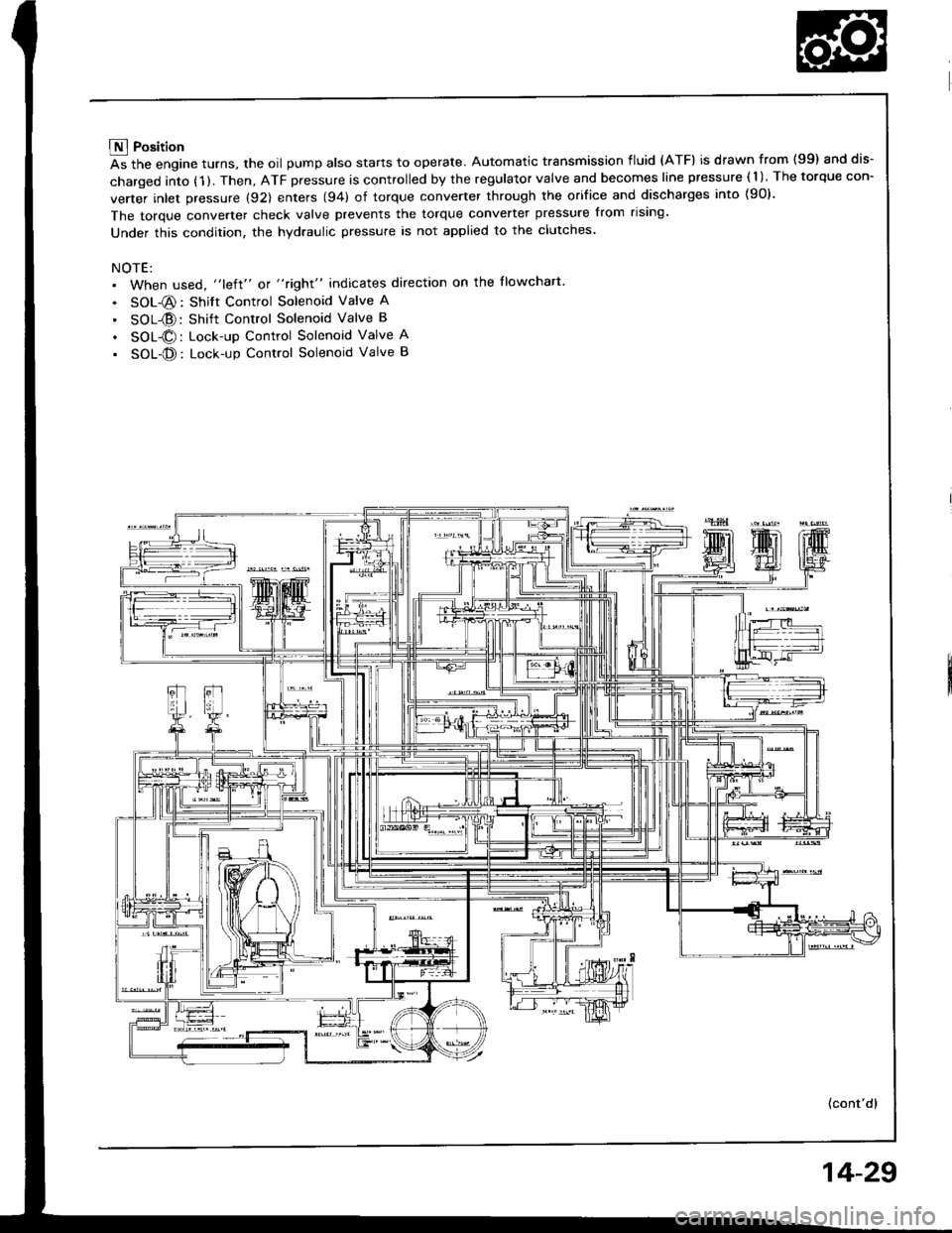
As the engine turns, the oil pump also starts to operate. Automatic transmission fluid (ATF) is drawn from (99) and dis-
charged into (1 ). Then, ATF pressure is controlled by the regulator valve and becomes line pressure ( 1 ). The torque con-
verter inlet pressure (92) enters (94) of torque converter through the orifice and discharges into {90}.
The torque converter check valve prevents the torque converter pressure from rising'
Under this condition, the hydraulic pressure is not applied to the clutches.
NOTE:. When used, "left" or "right" indicates direction on the llowchart
. SOL-@: Shift Control Solenoid Valve A
' SOL{D:Shift Control Solenoid Valve B
. SOL@: Lock-up Control Solenoid Valve A
. SOL-@: Lock-up Control Solenoid Valve B
(cont'd)
14-29
Page 426 of 1413
Description
Hydraulic Flow (cont'd)
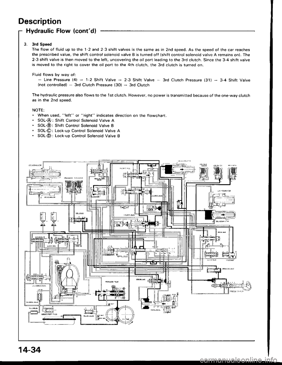
3rd Speed
The tlow of fluid up to the 1-2 and 2 3 shift valves is the same as in 2nd speed. As the speed of the car reaches
the prescribed value, the shift control solenoid valve B is turned off {shilt control solenoid valve A remains on). The
2-3 shift valve is then moved to the left, uncovering the oil port leading to the 3rd clutch. Since the 3-4 shitt valve
is moved to the right to cover the oil port to the 4th clutch, the 3rd clutch is turned on.
Fluid tlows by way of:- Line pressure l4l - 1-2 shift valve - 23 Shift Valve * 3rd ctutch pressure (31) - 3-4 shift valve(not controlled) 3rd Clutch Pressure (3O) - 3rd Clutch
The hydraulic pressure also flows to the l st clutch. However, no power is transmitted because of the one-way clutchas in the 2nd speed.
NOTE:. When used, "lett" o( " tight" indicates direction on the flowcharl.. SOL-@: Shift Control Solenoid Valve A. SOL-@:Shift Control Solenoid Valve B. SOL-O: Lock-up Control Solenoid Valve A. SOL-@: Lock-up Control Solenoid Valve B
14-34
Page 427 of 1413
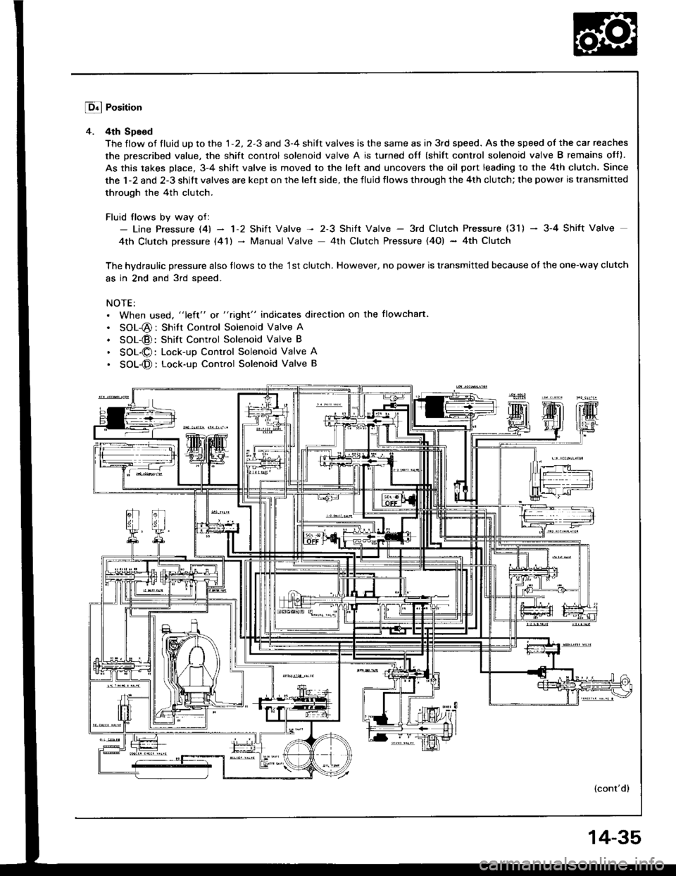
Lq4 Position
4. 4th Spe6d
The flow of tluid up to the 1-2, 2-3 and 3-4 shift valves is the same as in 3rd speed. As the speed of the car reaches
the prescribed value, the shift control solenoid valve A is turned oJt (shift control solenoid valve B remains off).
As this takes place, 3-4 shift valve is moved to the left and uncovers the oil port leading to the 4th clutch. Since
the 1-2 and 2-3 shift valves are kept on the left side, the fluid flows through the 4th clutch; the power is transmitted
through the 4th clutch.
Fluid flows by way of:- Line Pressure l4l - 'l'2 Shift Valve -t 2-3 Shitt Valve - 3rd Clutch Pressure (31) - 3-4 Shift Valve
4th Clutch pressure (41) - Manual Valve 4th Clutch Pressure {4O) - 4th Clutch
The hvdraulic pressure also tlows to the '1st clutch. However, no power is transmitted because of the one-way clutch
as in 2nd and 3rd soeed.
NOTE:. When used, "left" or "right" indicates direction on the flowchan.
. SOL-@: Shitt Control Solenoid Valve A
. SOL-@: Shift Control Solenoid Valve B
. SOL-O: Lock-up Control Solenoid Valve A
. SOL-@: Lock-up Conttol Solenoid Valve B
(cont'dl
14-35
Page 428 of 1413
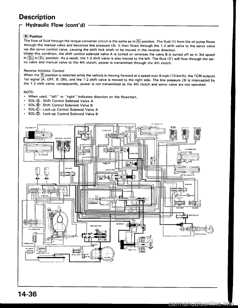
Description
Hydraulic Flow (cont'd)
LEI Position
The flow ot fluid through the torque convener circuit is the same as in S position. The tluid ( 1 ) trom the oil pump flowsthrough the manual valve and becomes line pressure (31. lt then flows through the 1-2 shift valve to the servo varvevia the servo control valve, causing the shift tork shatt to be moved in the reverse direction.Under this condition, the shift control solenoid valve A is turned on whereas the valve B is turned ofJ as in 3rd speedin [Dil or lDs]l position. As a result, the 1-2 shift valve is also moved to the left. The ftuid (3'] will ftow through the ser-vo valve and manual valve to the 4th clutch; power is transmitted through the 4th clutch.
Reverse Inhibitor Control
When the @ position is selected while the vehicle is moving forward at a speed over 6 mph ( 1O km/h). the TCM outputs1st signal (A: OFF, B: ON), and the 1-2 shift valve is moved to the right side. The line pressure {3) is intercepted bvthe 1-2 shift valve; consequently, power is not transmitted as the 4th clutch and servo valve are not oDerareo.
NOTE:. When used, "lefl" ot "tight" indicates direction on the flowchart.. SOL-@: Shift Control Solenoid Valve A. SOL€: Shift Control Solenoid Valve B. SOL€: Lock-up Control Solenoid Vatve A. SOL-@: Lock-up Control Sotenoid Vatve B
14-36
Page 430 of 1413
Description
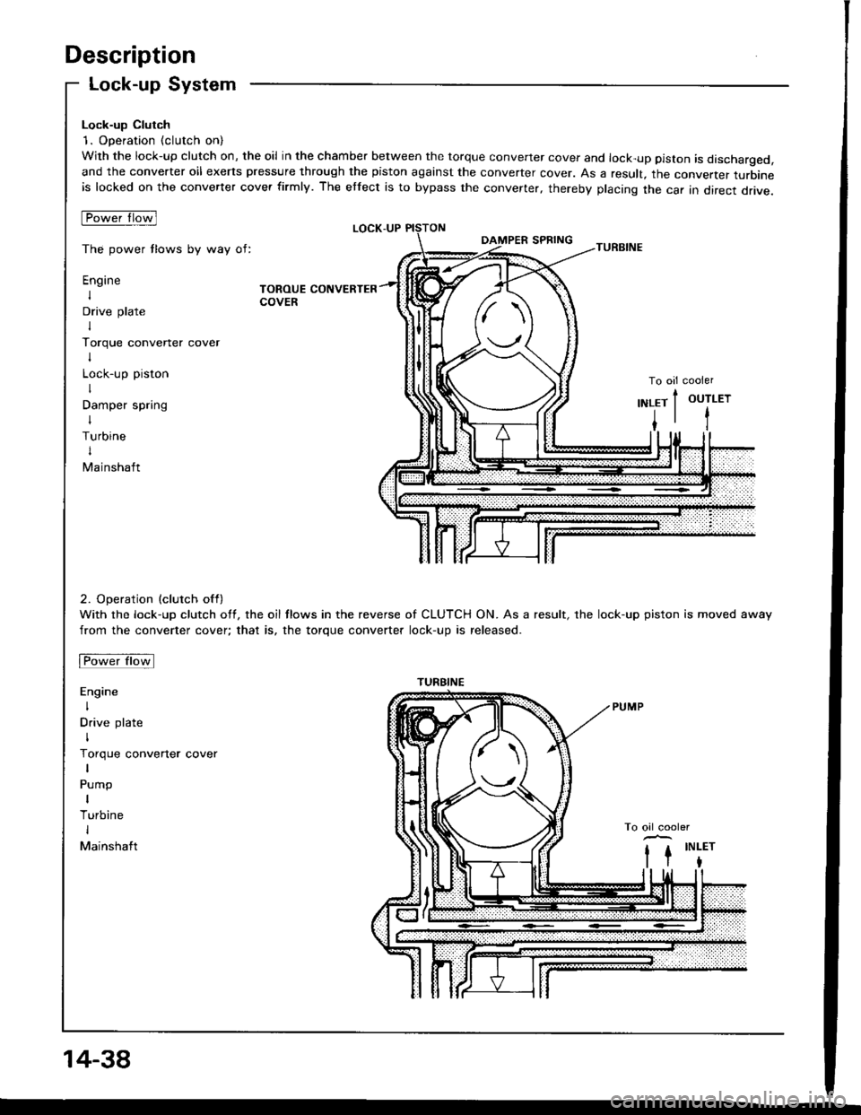
Lock-up System
Lock-up Clutch
1. Operation (clutch on)
With the lock-up clutch on, the oil in the chamber between the torque convener cover and lock-up piston is discharged,and the converter oil exerts pressure through the piston against the converter cover. As a result, the converter turbineis locked on the converter cover firmly. The etfect is to bypass the converter, thereby placing the car in direct drive.
tpowefJlo-wl
The power tlows by way of:
Engine
I
Drive plate
I
Torque convener cover
I
Lock-up piston
I
Damper spring
I
Turbine
t
Mainshaft
TOROUE CONVERTERCOVER
LOCK-UP
TURBINE
To oil cooler
2. Operation (clutch off)
With the lock-up clutch off, the oil tlows in the reverse of CLUTCH ON. As a result, the lock-up piston is moved away
from the converter cover; that is, the torque converter lock-up is released.
Fowtttowl
Engine
I
Drive plate
I
Torque converter cover
Pump
I
Turbine
I
Mainshaft
OUTLET
t
,\
TURBINE
14-38
Page 431 of 1413
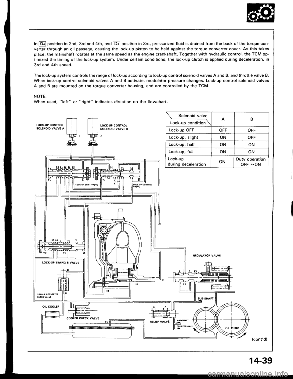
In E position in 2nd, 3rd and 4th, and @ position in 3rd, pressurized fluid is drained from the back of the torque con-
verter through an oil passage, causing the lock-up piston to be held against the torque converter cover. As this takes
place, the mainshaft rotates at the same speed as the engine crankshaft. Together with hydraulic control, the TCM op-
timized the timing ot the lock-up system. Under certain conditions, the lock-up clutch is applied during deceleration, in
3rd and 4th sDeed.
The lock-up system controls the range of lock-up according to lock-up control solenoid valves A and B, and throttle valve B.
When lock-up control solenoid valves A and B activate. modulator pressure changes. Lock-up control solenoid valves
A and B are mounted on the torque converter housing, and are controlled by the TCM.
NOTE:
When used, "left" or " tight" indicates direction on the tlowchart.
LOCK IJP COIITBOL
Solenoid valve
L""f."p "."aiti""\B
Lock-up OFFOFFOFF
Lock-up, slightONOFF
Lock-up, halfONON
Lock-up. fullONON
Lock-up
during decelerationONDuty operation
OFF -ON
LOCI( UP TIMII{G B VAIVE
{cont'd)
ott coot€R
14-39
Page 435 of 1413
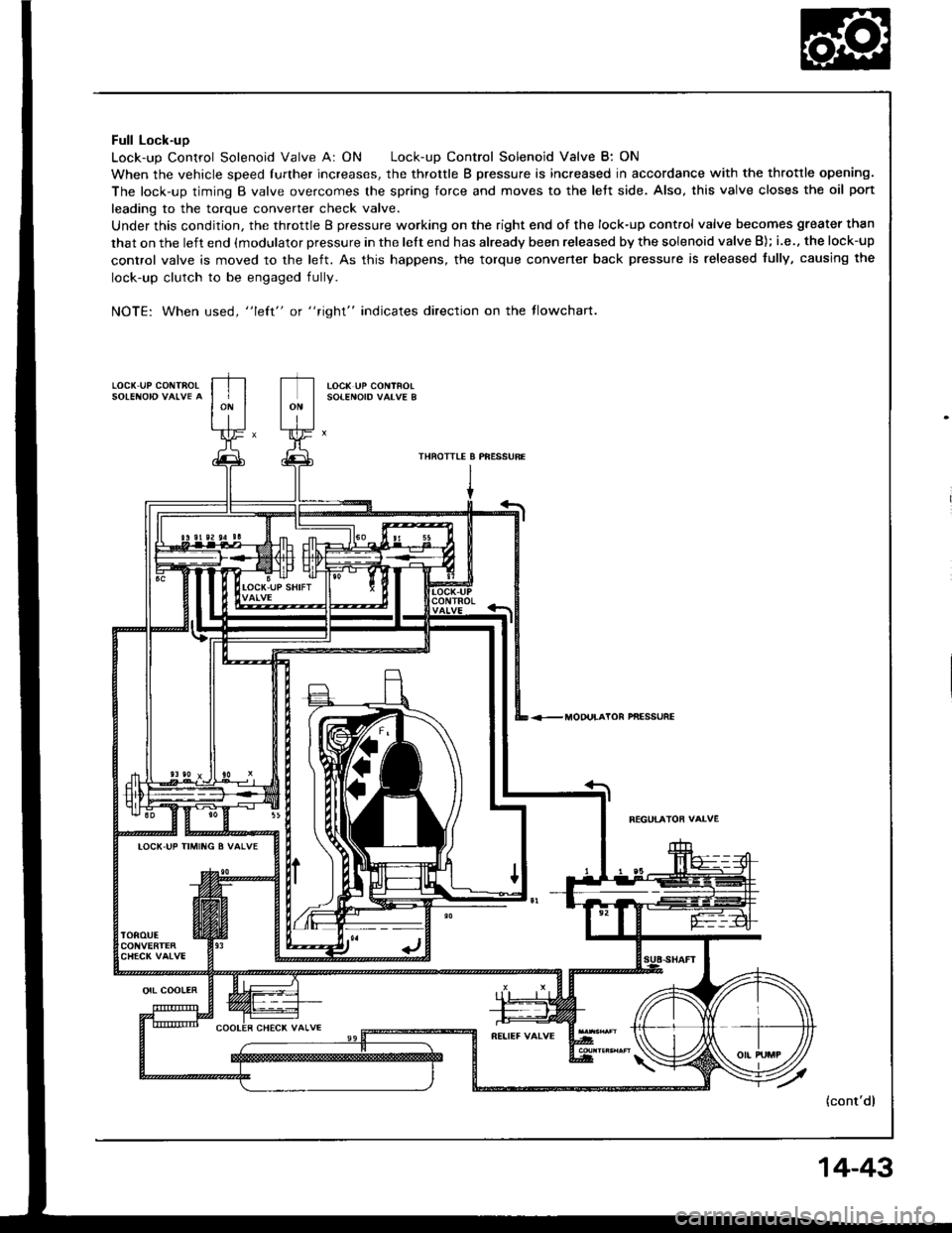
Full Lock-uo
Lock-up Control Solenoid Valve A: ON Lock-up Control Solenoid Valve B: ON
When the vehicle speed fufther increases, the throttle B pressure is increased in accordance with the throttle opening.
The lock-up timing B valve overcomes the spring force and moves to the left side. Also, this valve closes the oil port
leading to the torque converter check valve.
Under this condition, the throttle B pressure working on the right end of the lock-up control valve becomes greater than
that on the left end (modulator pressure in the lelt end has already been released by the solenoid valve B); i.e., the lock-up
control valve is moved to the left. As this happens, the torque convener back pressure is released fully, causing the
lock-up clutch to be engaged fully.
NOTE: When used, "left" or "right" indicates direction on the tlowchart.
LOC( UP COi{TAO!toc( uP coNtnolSOIENOID VAIVE B
THRO]TIE A PFESSURE
PNESSUFE
FEGUTATOF VAIVE
LOCK-UP TIMIIIG B VALVE
(cont'd)
orl cootER
14-43
Page 443 of 1413
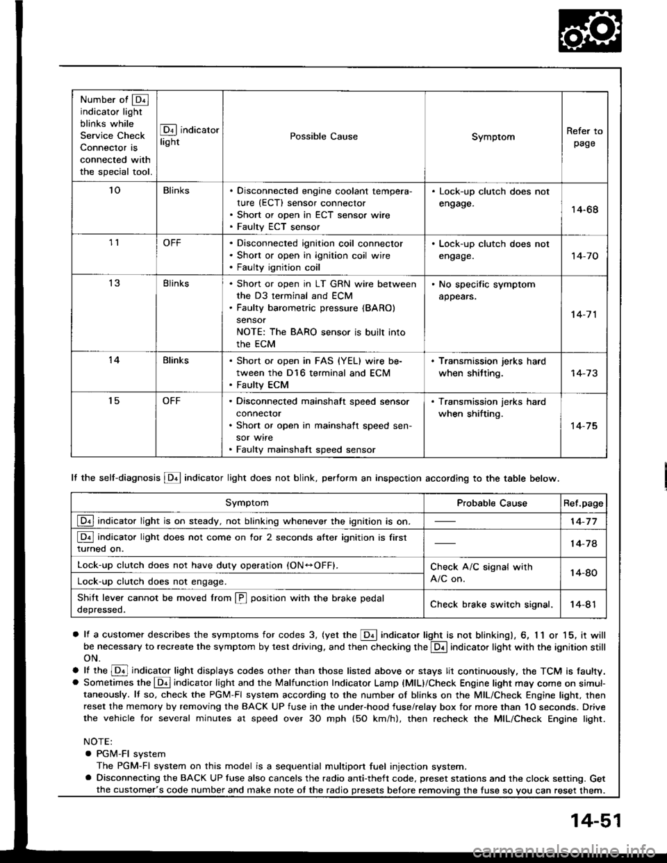
Number of @indicator light
blinks while
Service Check
Connector is
connected with
the special tool.
@ indicator
lightPossible CauseSymptomRefer to
page
'loBlinksDisconnected engine coolant tempera-
rure (ECT) sensor connector
Short or open in ECT sensor wire
Faulty ECT sensor
Lock-up clutch does not
engage.14-68
1lOFFDisconnected ignition coil connector
Short or open in ignition coil wire
Faulty ignition coil
. Lock-up clutch does not
engage.'t 4-7 0
13Blinks. Shon or open in LT GRN wire between
the D3 terminal and ECM. Faulty barometric pressure {BARO)
sensor
NOTE: The BARO sensor is built into
the ECM
. No specific symptom
appears.
14-7 1
14Blinks. Short of open in FAS {YEL} wire be-
tween the D16 terminal and ECM. Faulty ECM
. Transmission jerks hard
when shitting.
't5OFFDisconnected mainshaft speed sensor
connecror
Short or open in mainshaft speed sen-
sor wire
Faulty mainshaft speed sensor
. Transmission jerks hard
when shifting.
14-75
SymptomProbable CauseRet.page
LQ! indicator light is on steady, not blinking whenever the ignition is on.14-77
[Q3] indicator light does not come on for 2 seconds after ignition is first
turned on.14-78
Lock-up clutch does not have duty operation (ON-OFFI.Check A/C signal with
A/C on.14-80Lock-up clutch does not engage.
Shitt leve. cannot be moved lrom @ position with the brake pedal
depressed.Check brake switch signal,14-41
It the self-diagnosis LQ4 indicator light does not blink, perform an inspection according to the table below.
a lf a customer describes the symptoms for codes 3, (yet the LQ! indicator light is not blinkingl, 6, 1 1 or 15, it will
be necessa.y to recreate the symptom by test driving. and then checking the @ indicator light with the ignition still
oN.
e lt ttre @ indicator light displays codes olher than those listed above or stays lit continuously, the TCM is faulty.. Sometimes the Lqd indicator light and the Malfunction Indicator Lamp (MlL)/Check Engine light may come on simul-taneously. lf so, check the PGM-Fl system according to the numbe. of blinks on the MIL/Check Engine light. thenreset the memory by removing the BACK UP fuse in the unde.-hood fuse/relay box for more than 1O seconds. Drive
the vehicle for several minutes at speed over 30 mph (5O km/h), then recheck the MIL/Check Engine light.
NOTE:
. PGM-FI system
The PGM-Fl system on this model is a sequential multiport fuel injection system.a Disconnecting the BACK UP luse also cancels the radio anti-theft code. preset stations and the clock setting. Get
the fuse so vou can reset them.the customer's code number and make note ot the radio
14-51