mirror HONDA INTEGRA 1994 4.G Workshop Manual
[x] Cancel search | Manufacturer: HONDA, Model Year: 1994, Model line: INTEGRA, Model: HONDA INTEGRA 1994 4.GPages: 1413, PDF Size: 37.94 MB
Page 918 of 1413

Mirrors
Power Door Mirror Replacement
Hstchback
1. Pry out the cover panel with a flat tip screwdriver,
then remove it.
CAUTION: When prying with a flat tip screwdriver.
w'ap it whh protoctiva tapo to pravont damage.
2. Disconnect the connector. Remove the nuts, then
remove the door mirror while holdino it.
< : Nut locltion3, 3
^^ sxo.8mm I
l$9 111 - to.+ rst.. i| +|lmtu.+rgr.m, I3 lbl'lrl - ---J'/
cot{t{EcToB(Doo. mirror ddol
DOOR MIRROR
CONNECTORlDoor harnoss.ide)
CONNECTOR
3. Installation is the reverse o{ the removal procedure.
Sedan
1. Remove the door panel (see page 20-201 and dis-connect the connector.
2. Pry the cover panel out with a flat tip screwdriver,
then remove the cover panel.
CAUTION: Whsn prying with a flat tip scrowd.lv€l,
wrap it with protectiv€ taps to p.svont damag6.
3. Remove the screws while holding the door mirror.
< i Scrow locations
, A< : Scrow, 2 , B< : Scr6w, I
! ,"",''@ I 66
I s'0.4.- | sro.'"e-.
4 N.m (0.4 kst.m, + w.m (0.4 kgt.m,\3_!!t.rrr__ \!Lbllq
CONNECTOR
4. Installation is the reverse of the removal procedure,
HOOKS
20-49
Page 919 of 1413
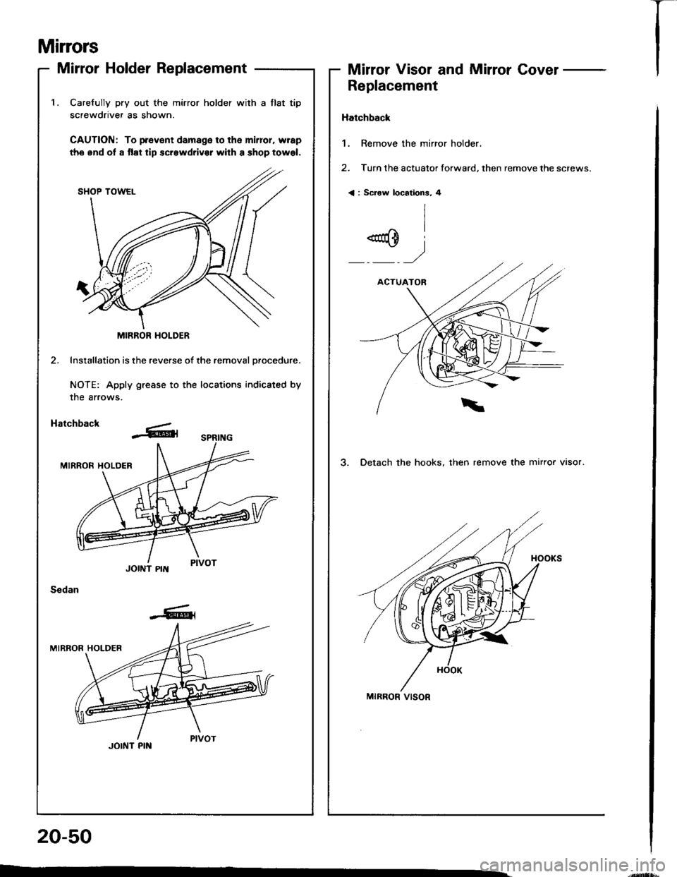
1. Carefully pry out the mirror holder with a tlat tip
screwdriver as shown.
CAUTION: To p.ev€nt damage to tha mirlor, wrap
ths end ot a tlat tip screwdriv€r with a shop towel.
MIRROR HOLDER
2. Installation is the reverse of the removal orocedure.
NOTE: Apply grease to the locations indicated by
the arrows.
Hatchback
JOINT PIN
Sedan
JOINT PIN
Mirrors
Mirror Holder ReplacementMirror Visor and Mirror Covel -
Replacement
Hatchback
1. Remove the mirror holder.
2. Turn the actuator forward. then remove the screws.
< : Scraw location3, 4
3. Detach the hooks, then remove the mirror visor.
MIRROR VISOR
20-50
I
Page 920 of 1413
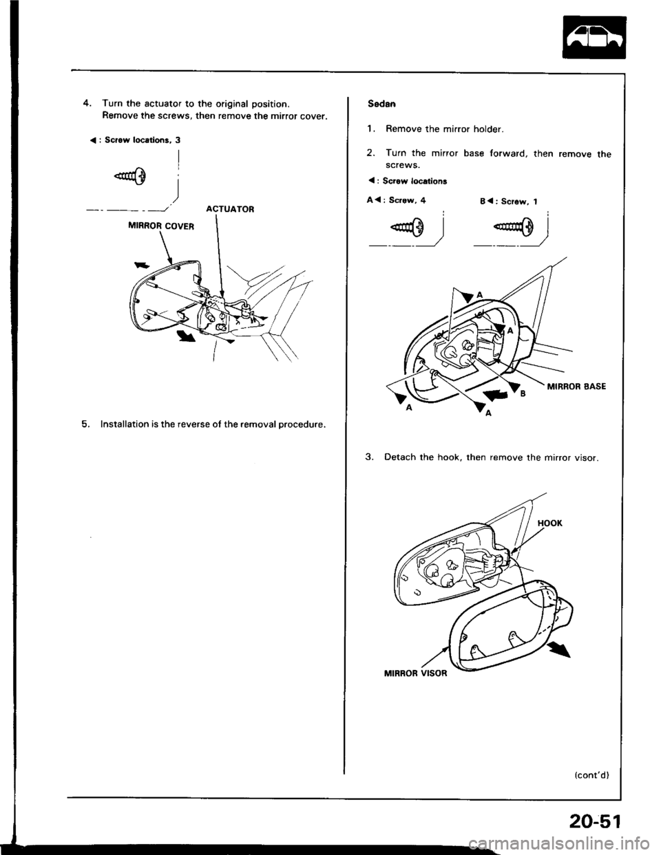
4. Turn the actuator to the original position.
Remove the screws, then remove the mirror cover.
< : Scrow locttions, 3
ACTUATOR
5, Installation is the reverse ol the removal Drocedure,
Sedan
1, Remove the mirror holder.
2. Turn the mirror base forward, then
screws.
< : Sciow location!
A< : Sc.ew, 48<: Screw, I
@ I 4E0 l_J _._J
MIRROR BASE
3. Detach the hook. then remove the mirror visor.
{cont'd)
remove the
-
20-51
Page 921 of 1413
Mirrors
Mirror Visor and Mirrol Covel
Replacement {cont'd)
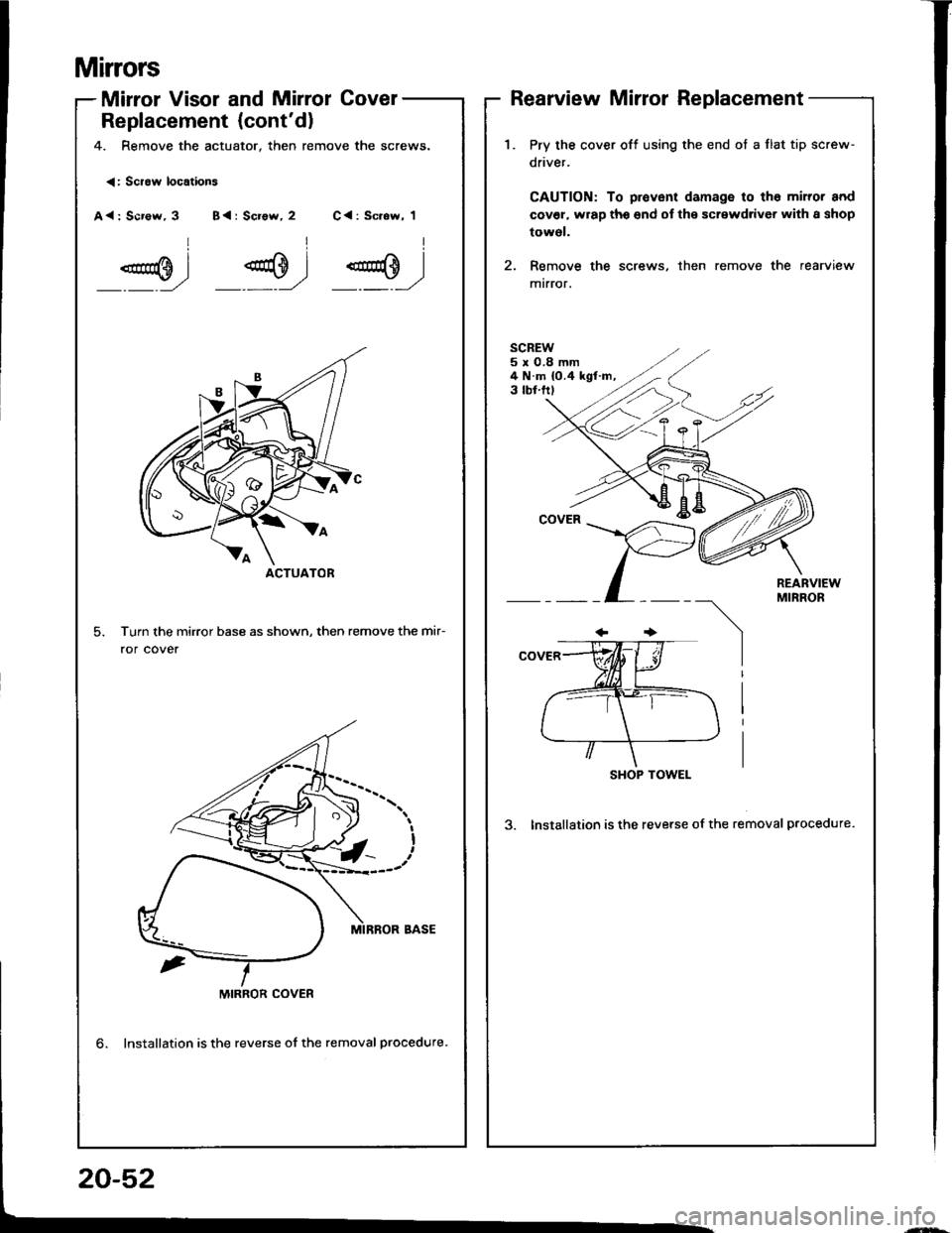
4. Remove the actuator, then remove the screws.
Rearview Mirror Replacement
<: Scraw locations
A<: Scr€w, 3 B{: Screw, 2 C<: Sc.ew, 1
Turn the mirror base as shown, then remove the mir-
ror cover
ACTUATOR
1.Pry the cover off using the end ot a flat tip screw-
driver.
CAUTION: To provent damage to tho miror and
cov€l, wrap tho end of the screwdriver with I shop
towol.
Remove the screws, then remove the rearview
mtrror.
SCREW5x0.8mm4 N.m {0.4 kgf.m,3 tbf.ftl
REARVIEWMIRROR
SHOP TOWEL
3. Installation is the reverse of the removal procedure.
MIRROR COVER
lnstallation is the reverse of the removal procedure.
20-52
Page 967 of 1413
Headliner
Replacement
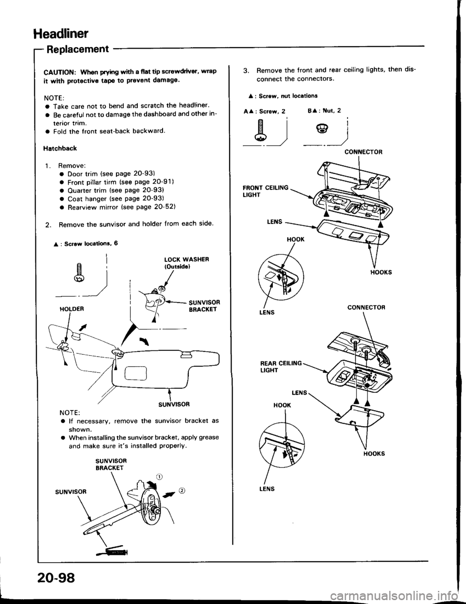
CAUTION: Whon Fyhg with I flat tip sclewdrivsr, wrap
it whh protectivs tapo to prevent damaga.
NOTE:
a Take care not to bend and scratch the headliner.
a Be caretul not to damage the dashboard and other in-
terior lrim.
a Fold the front seat-back backward.
Halchback
1. Remove;
. Door trim (see page 20-93)
a Front Dillar tirm {see page 20-91)
a Ouarter trim (see page 20-93)
a Coat hanger (see page 20-93)
a Rearview mirror {see page 20-52)
2. Remove the sunvisor and holder from each side.
: Scrow location!, 6
al
u)
LOCK WASHER(Outside)
"^/
HAaqr+- SUNV|SOR
Y
BRACKETHOLDEB
NOTE:
a lf necessary, remove the sunvisor bracket as
shown.
a When installing the sunvisor bracket, apply grease
and make sure it's installed properly.
suNvlsoRBRACKET
suNvrsoR
20-98
3. Remove the tront and rear ceiling lights, then dis-
connect the conneclors.
: Sc.ew, nut localions
A
: Scrcw, 2B
: Nut, 2
&)?)
HOOK
A
ffi)
LENS
HOOK
I
,r--T-\
m)
H
LENS
CONNECTOR
CONNECTOR
HOOKS
Page 969 of 1413
Headliner
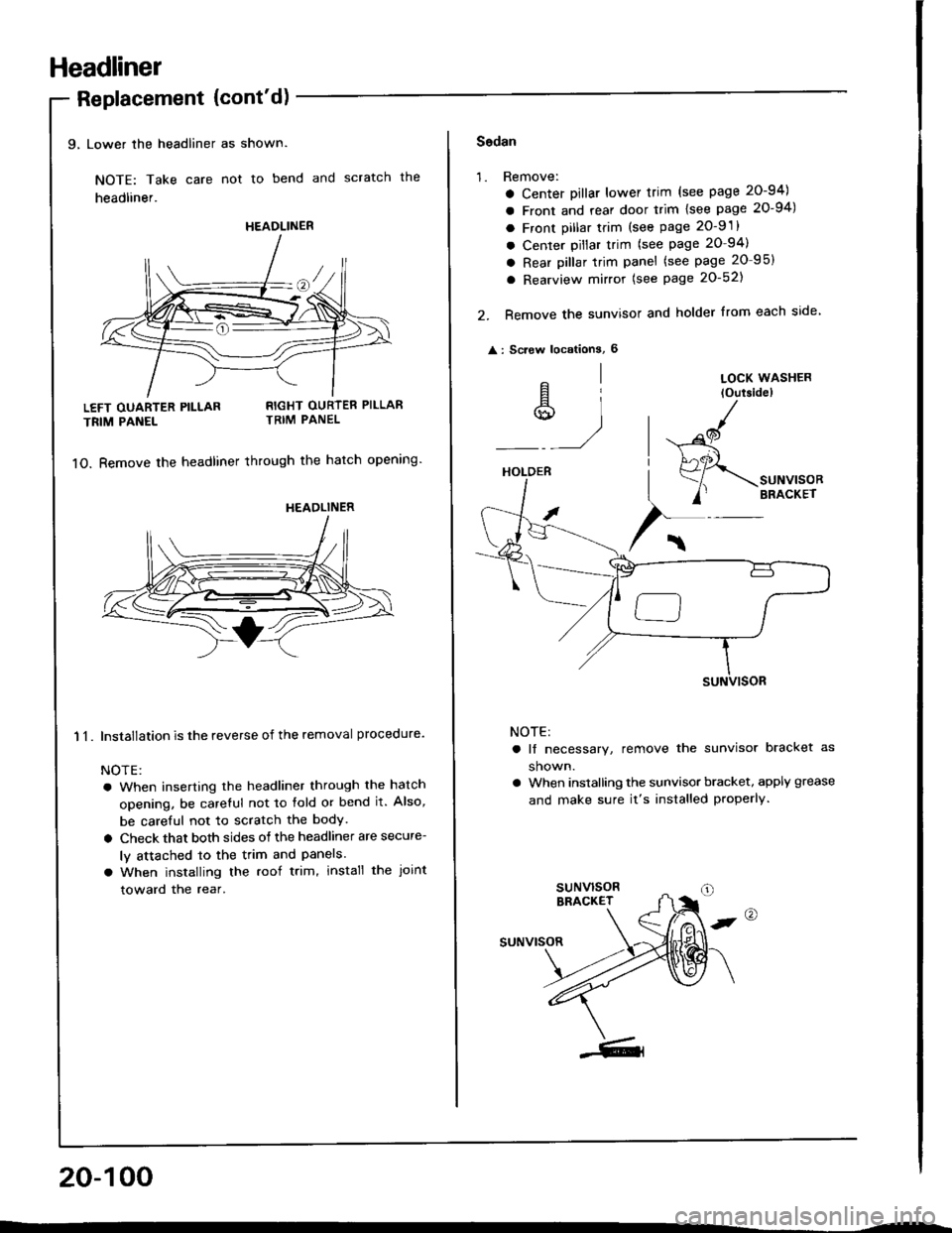
9, Lower the headliner as shown.
NOTE: Take care not to bend and scratch the
headliner.
Replacement {cont'd)
LEFT OUARTER PILLAR
TRIM PANEL
11.
RIGHT OURTER PILLARTRIM PANEL
1O. Bemove the headliner through the hatch opening'
Installation is the reverse of the removal procedure.
NOTE:
a When inserting the headliner through the hatch
opening, be careful not to fold or bend it. Also,
be careful not to scratch the bodY.
a Check that both sides of the headliner are secure-
ly attached to the trim and Panels.
a When installing the roof trim, install the Joint
toward the rear.
20-100
HEADLINER
HEADLINER
Sodan
'1.Remove:
a Center Dillar lower trim (see page 20-94)
a Front and rear door trim lsee page 20-94)
a Front pillar trim (see page 2O-9 .
a Center pillar trim (see page 20-94)
a Rear pillar trim panel (see page 20 95)
a Rearview mirror (see Page 20-521
Remove the sunvisor and holder from each side
: Screw locationS, 6
2.
^l
s,1
LOCK WASHER
loutsidel
HOLDER
/
$-.unu,"o"
/' BRACKET
NOTE:
a lf necessary, remove the sunvisor bracket as
shown.
a When installing the sunvisor bracket, apply grease
and make sure it's installed properly.
,@
suNvrsoR
Page 1140 of 1413
Connector ldentification and Wire Harness Routing
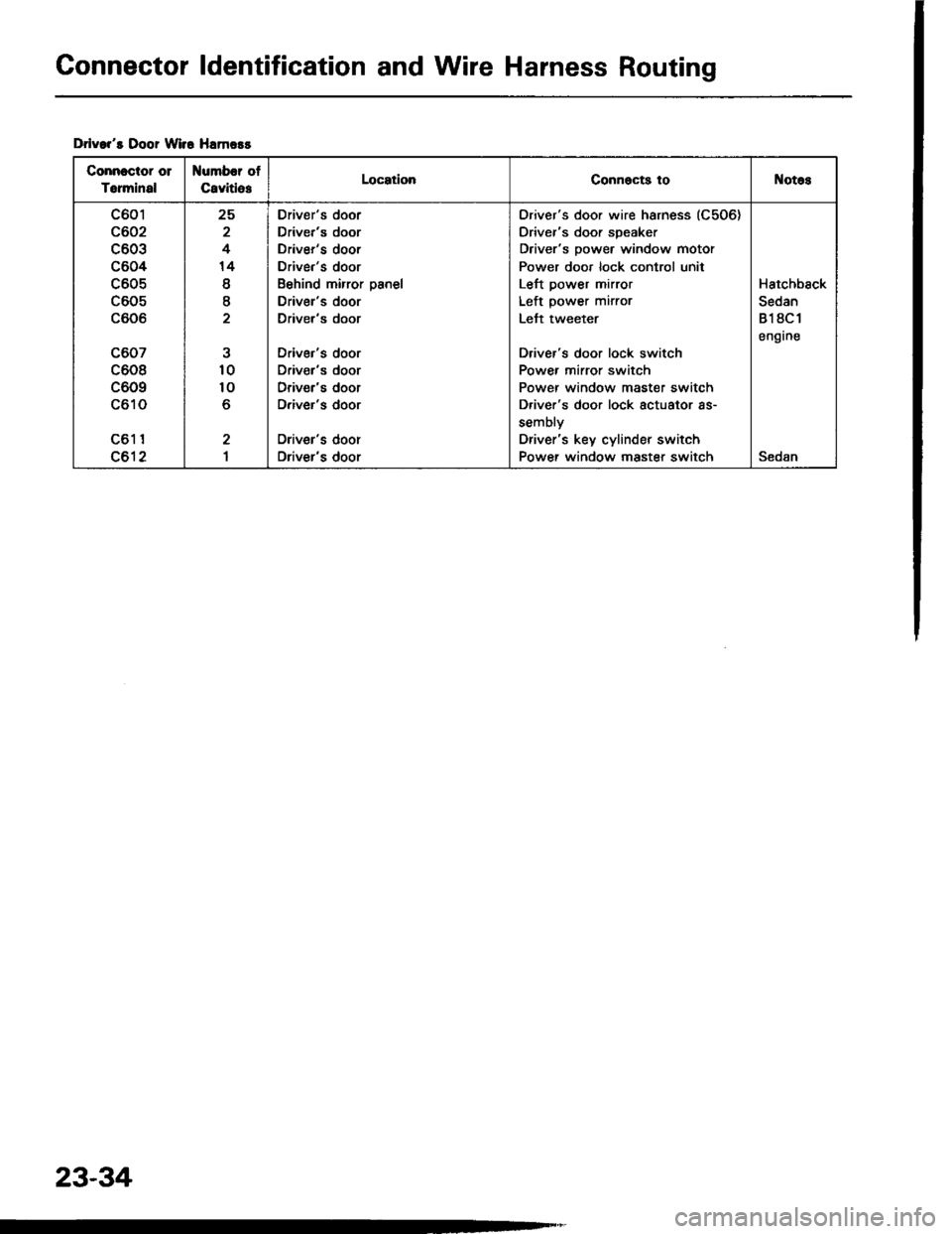
Drlvar's Door Wir6 Hamors
Connectot 01
Torminal
Number of
CavitlesLocationConnocts toNotos
c601
c602
c603
c604
c605
c605
c606
c607
c608
c609
c610
c61 1
c612
25
2
4
14
I
I
10
10
o
2
I
Driver's door
Driver's door
Driver's door
Driver's door
Behind mirror panel
Driver's door
Driver's door
Driver's door
Driv€r's door
Driver's door
Driver's door
Oriver's door
Driver's door
Oriver's door wire harness (C506)
Driver's door speaker
Driver's power window motor
Power door lock control unit
Left power mirror
Left power mirror
Lett tweeter
Driver's door lock switch
Power mirror switch
Power window master switch
D.iver's door lock actuator as-
sembly
Driver's key cylinder switch
Power window master switchSedan
Hatchback
Sedan
818C1
engrne
23-34
Page 1142 of 1413
Connector ldentification and Wire Harness Routing
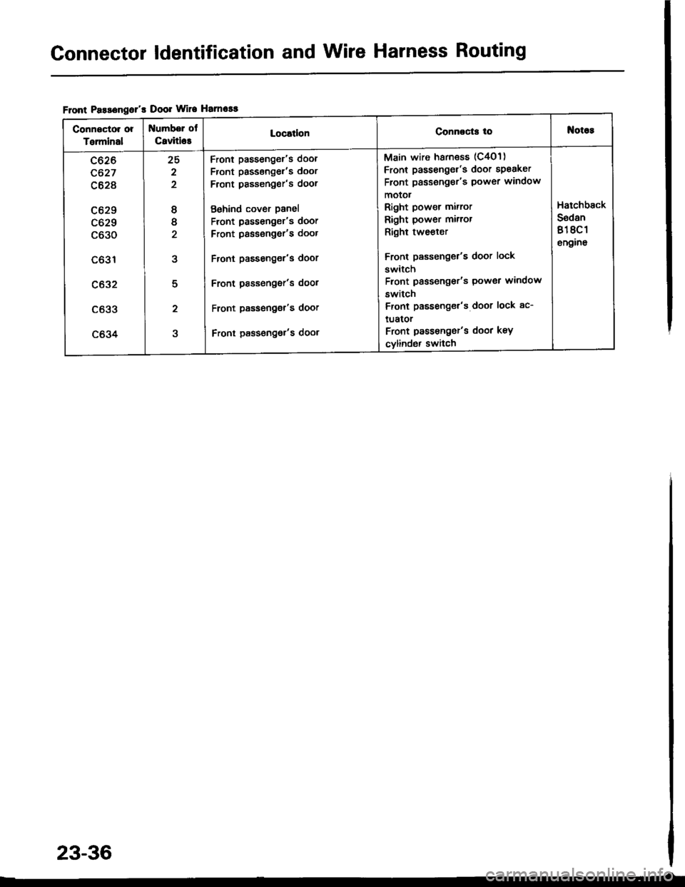
Flont Pasa€ngol's Door Wire Hamosg
Conngctor or
Talminal
Numbel of
C8viti63LocatlonConnocts toNot6s
c626
c627
c628
c629
c629
c630
c631
c632
c633
c634
25
2
2
8
tt
2
5
2
Front passenger's door
Front passsngel'�s door
Front pssseng€r's door
Behind cover panel
Front passenger's door
Front passengor's door
Front passenger's door
Front Passonger's dool
Front passeng€r's door
Front pass€ngot's door
Main wire harness (C4O1)
Front passenger's door speaker
Front passeng€r's power window
motot
Right power mirror
Right power mirror
Right tweeler
Front passenger's door lock
switch
Front passengor's Power window
switch
Front passenget's door lock ac-
tuator
Front passengor's door key
cylind6r switch
Hatchback
S6dan
818C 1
6n9ino
23-36
Page 1322 of 1413
Power Mirrors
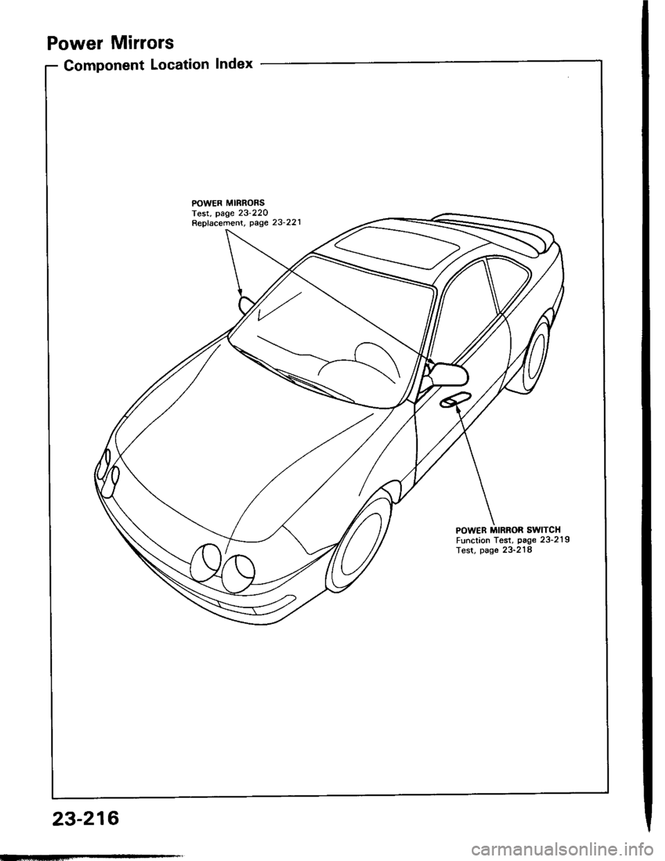
Component Location Index
POWER MIRRONSTest, page 23'220Repfacement, page 23'221
POWER MIRROR SWITCHFunction Test, page 23'219Test, page 23-218
23-216
Page 1324 of 1413
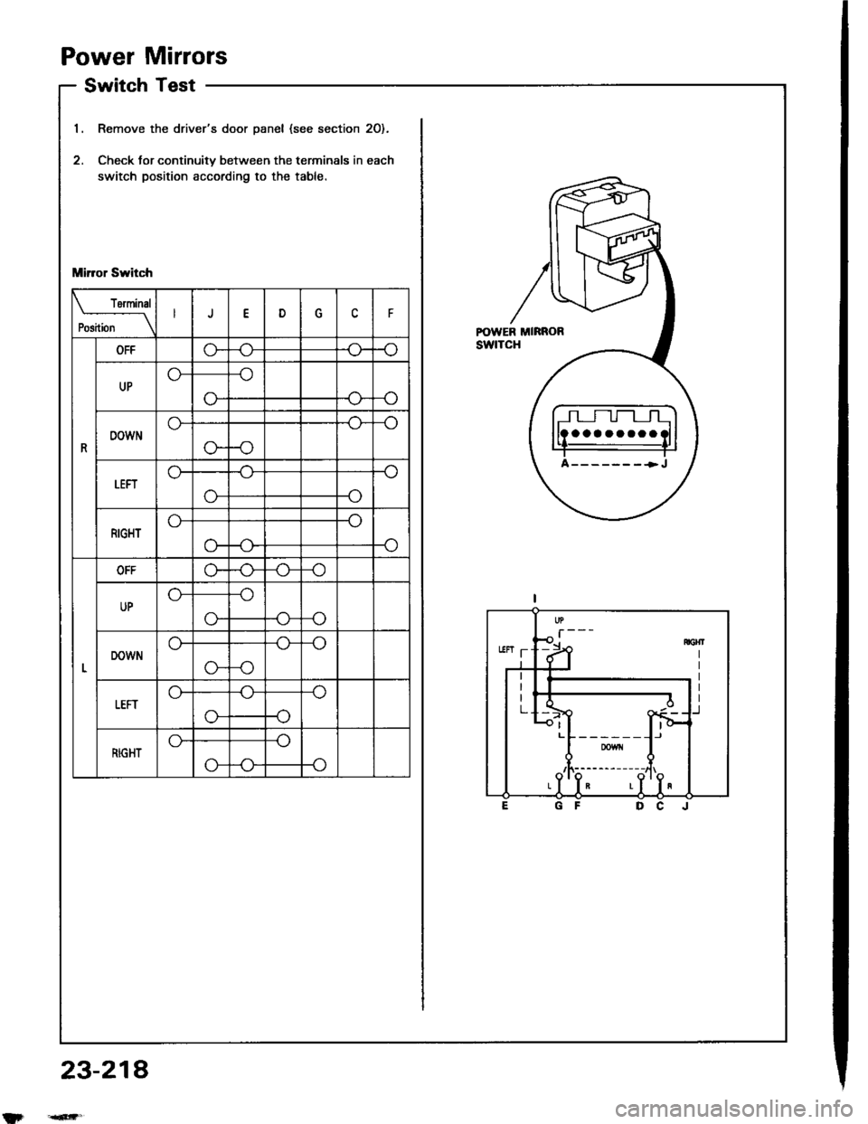
Power Mirrors
Switch Test
Remove the driver's door panel (see section 2O).
Check tor continuitv between the terminals in each
switch position according to the table.
Mirror Switch
rermrnal
Position \J
R
OFFG"
UP
-o
o--<>-
DOWN
-o
o--o
LEFTo-
-o
RIGHT
-o
o-
OFFo--o
UP
o--(J_
DOWN
-o
G--o
tEFT
-o
-o
RIGHTG-
P-o
23-214
aaaaaaaa
A-------+J