window HONDA INTEGRA 1994 4.G User Guide
[x] Cancel search | Manufacturer: HONDA, Model Year: 1994, Model line: INTEGRA, Model: HONDA INTEGRA 1994 4.GPages: 1413, PDF Size: 37.94 MB
Page 936 of 1413
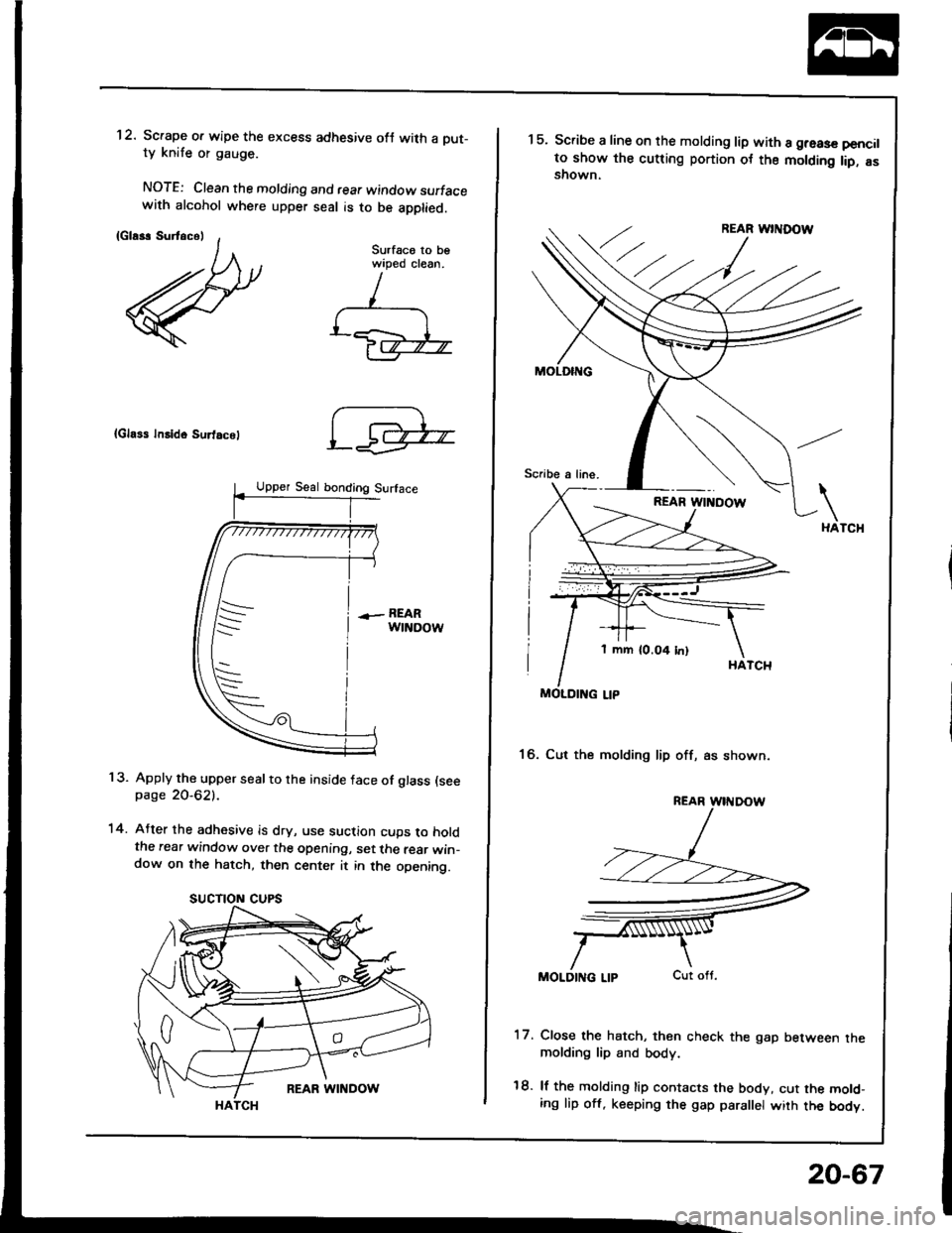
1 2. Scrape o. wipe the excess adhesive ofJ with a Dut-ty knife or gauge.
NOTE: Clean the molding and rear window surfacewith alcohol where upper seal is to be apptied.
{Gla*r SurtacelSurfaco to bewiped clean.
{Gla$ Insido Surtacel
13. Apply the upper seal to the inside face of glass (seepage 2O-621.
14. After the adhesive is dry, use suction cups to holdthe rear window over the opening, set the rear win-dow on the hatch, then center it in the opening.
SUCTION CUPS
1 mm (0.04 In)
1 5. Scribe a line on the molding lip with a greas€ pencilto show the cutting portion ot the molding lip, asshown.
16. Cut the molding lip off, as shown.
MOLDING LIP
17. Close the hatch, then check the gap between themolding lip and body.
18. lf the molding lip contacts the body, cut the mold-ing lip off. keeping the gap para el wiih the body.
20-67
Page 937 of 1413
Rear Window
Removal
Sadan
CAUTION:
a Wear gloves to remove and install the leal window.
a Do not damage the delloster grid lines.
1. To remove the rear window, f irst remove:
. Trunk lid {see page 20-149)
a Rear seat-back side bolsters (see page 20-11 1)
. Rear shelf (see page 2O-95)
a Rear pillar trim panel {see page 20 95)
2. Disconnect the defroster leads, and remove their
holders.
NOTE: Avoid scratching the rear window with the
cutter blade.
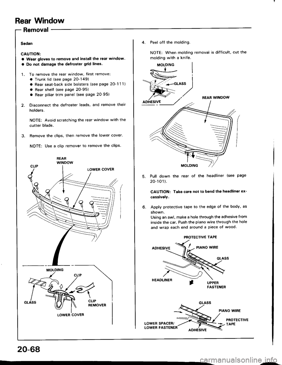
3. Remove the clips, then remove the lower cover.
NOTE: Use a clip remover to remove lhe clips.
REARwlNDow
MOLDING
LOWER COVER
20-68
---
4. Peel off the molding.
NOTE: When molding removal is difficult, cut the
molding with a knife.
MOLOING
REAR WINOOW
Pull down the rear of the headliner (see page
20-101).
CAUTION: Take care not to bend the headliner ex-
cessively.
Apply protective tape to the edge of the body, as
shown.
Using an awl. make a hole through the adhesive from
inside the car. Push the piano wire through the hole
and wrap each end around a piece of wood.
ADHESIVE/ - a,o*o *'*a
HEADLINER
PIANO WIRE
LowERsPAcER/ ;ru/
PRorEcrtvE
LowER FASTENER oore,srvr \3 rlee
o.
S
PROTECTIVE TAPE
Page 938 of 1413
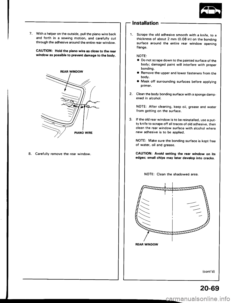
7.With a helper on the outside, pullthe piano wire backand torth in a sawing motion, and carelully cutthrough the adhesive around the entire rear window.
CAUTION: Hold tho piano wir€ as closo to the realwindow as possible to prevent damage to the body.
REAR WINDOW
PIANO wlRE
8. Carefully remove the rear window.
Installation
Scrape the old adhesive smooth with a knite, to athickness of about 2 mm (O.08 in) on the bondingsurface around the entire rear window openingflange.
a Do not scrape down to the painted sudace of thebody; damaged paint will interfere with proper
bonding.
a Remove the upper and lower fasteners trom thebody.
a Mask off surrounding surfaces before applying
Dflmer.
2. Clean the body bonding surface with a sponge damp-ened in alcohol.
NOTE: After cleaning, keep oil, grease and water
from getting on the surface.
3. ll the old rear window is to be reinstalled, use a Dut-ty knife to scrape oft all traces of old adhesive. thenclean the rear window surface with alcohol wherenew adhesive is to be aDolied.
NOTE: Make sure the bonding surface is kept freeof water, oil and grease.
CAUTION: Avoid setting the rear window on itsedges; small chips may later develop into cracks.
Clean the shadowed area.
{cont'd)
/s
\--
t\
20-69
Page 939 of 1413
Rear Window
lnstallation (cont'd)
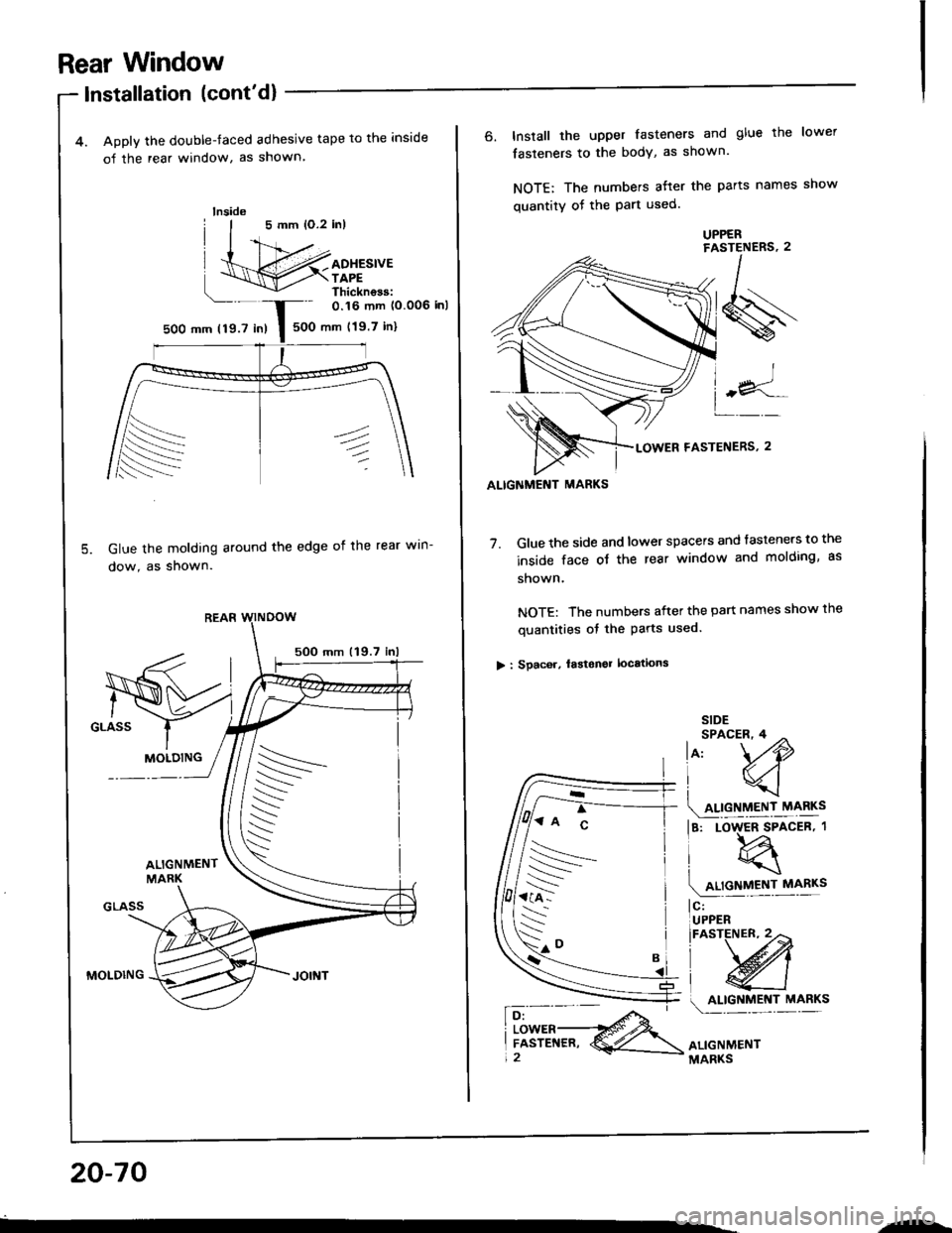
4. Apply the double-faced adhesive tape to the inside
o{ the rear window, as shown
Glue the molding around the edge oi the rear win-
dow, as shown.
5OO mm 119.7
MOLDING
lnside
0.16 mm (0.006 inl
500 mm (19.7 in)5OO mm 119.7 in)
MOLDING
ALIGNMENT MARKS
6. Install the upper fasteners and glue the lower
fasteners to the bodY, as shown.
NOTE: The numbers atter the parts names show
quantity of the Part used.
7. Glue the side and lower spacers and tasteners to the
inside face ot the rear window and molding, as
shown.
NOTE: The numbers after the part names show the
quantities of the Parts used.
> : Spac6r, lastonel locations
SIDESPACER,4 ^
lo, \./O
lq
4!9!llEN,r_r\,ry!s
la, Loqrcen.t
(4relycv!|I!"
l$;*
\'*'w
o.f9!T.nl "1"*"
ALIGNMENTMARKS
'7:^ c
rs
--
s-."
20-70
"-
Page 940 of 1413
ALIGT{MENT MARKS
S
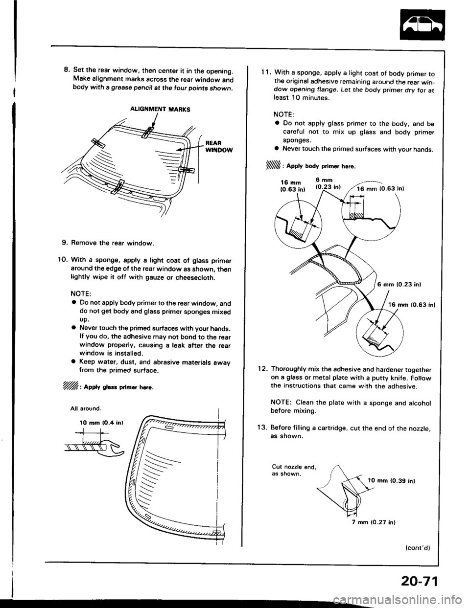
8. Set the rear window, then center it in the opening.Make alignment marks across the rear window andbody with a gfease pencil at the tout Doints shown.
9. Remove the rear window.
O. With a sponge, apply a light coat of glass primer
around the edge of the rear window as shown, thenlightly wipe it otf with gauze or cheesecloth.
NOTE:
a Do not apply body primer to the rear window, anddo not get body and glass primer sponges mixedup.
a Never touch the primed surfac€s with your hands.lf you do, the adhesive may not bond to the rearwindow prope.ly, causing a leak after the rearwindow is installed.
a Keep water. dust, and abrasive materials awavf,om the D.imed surtace.
72/: Appl,t gltst onmrr sctc.
All around.
10 mm lO.4 inl
/.s
s
20-71
1 1. With a sponge. appty a light coat ot body primer rothe original adhesive remaining around the rear win-dow opening flange. Let the body p.imer d.y tor atleast 10 minutes.
NOTE:
a Do not apply glass primer to the body, and be
careful not to mix up glass and body primer
sponges.
a Never touch the primed surfaces with vour hands.
l//////1,: appv body p'imo' hero.
;o:d:';", i"lT16 mm 10.63 inl
6 mm 10.23 inl
16 mm 10.63 inl
12. Thoroughly mix the adhesive and hardener togetheron a glass or metal plate with a putty knife. Fo owthe instructions that came with the adhesive.
NOTE: Clean the plate with a sponge and alcoholbefore mixing.
13. Before filling a cartridge, cut the end of the nozzle,as shown.
10 mm (0.39 in)
7 mm (0.27 inl
{cont'd)
Page 941 of 1413
Rear Wndow
Installation (cont'dl
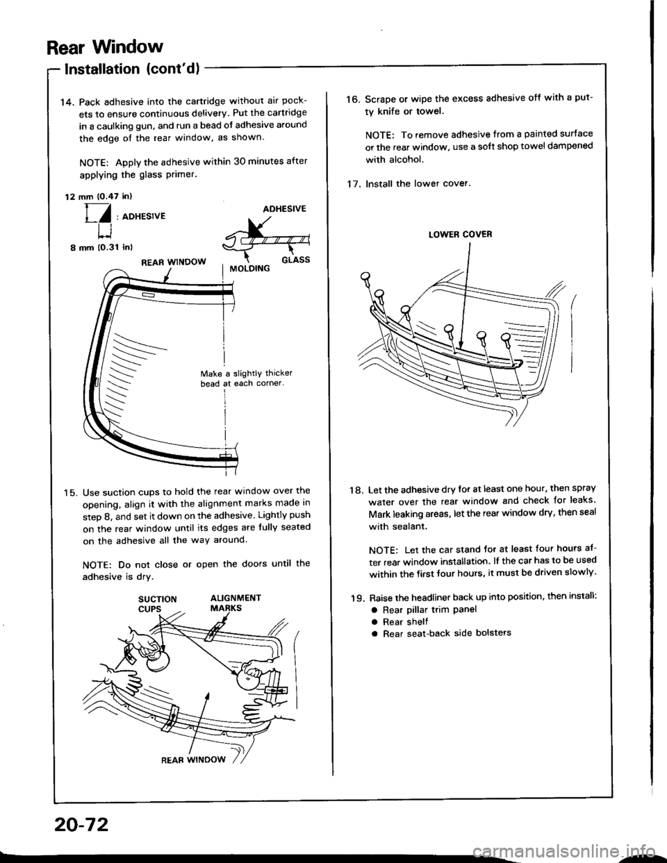
14. Pack adhesive into the cartridge without air pock-
ets to ensure continuous delivery. Put the cartridge
in a caulking gun, and run a bead of adhesive around
the edge oI the rear window, as shown.
NOTE: Apply the adhesive within 30 minutes after
applying the glass Primer.
12 mm (O.47 inl
[/ , aoxesrveADHESIVE
^X-"--"-,s-_T--r-
cr-rssI MOLOING
t-l
8 mm (o,31 inl
15.
REAR WINDOW
Use suction cups to hold the rear window over the
opening, align it with the alignment marks made in
step 8, and set it down on the adhesive Lightly push
on the rear window until its edges are fully seated
on the adhesive all the way around.
NOTE: Do not close or open the doors until the
adhesive is drv.
SUCTION ALIGNMENT
20-72
.-
16. Scrape or wipe the excess adhesive off with a put-
ty knife or towel.
NOTE: To remove adhesive from a painted surtace
or the rear window, use a soft shop towel dampened
with alcohol.
17. Install the lower cover.
'18. Let the adhesive dry for at least one hour, then spray
water over the rear window and check Jor leaks'
Mark leaking areas, let the rear window dry, then seal
with sealant.
NOTE: Let the car stand Jo. at least four hours af-
ter rear window installation, lf the car has to be used
within the tirst tour hours, it must be driven slowly'
19. Raise the headliner back up into position, then install:
a Rear pillar t.im Panela Rear shelf
a Rear seat-back side bolstels
Page 964 of 1413
Roar pillar tlim panel/Rear shell trim panel/Rsar she removal:
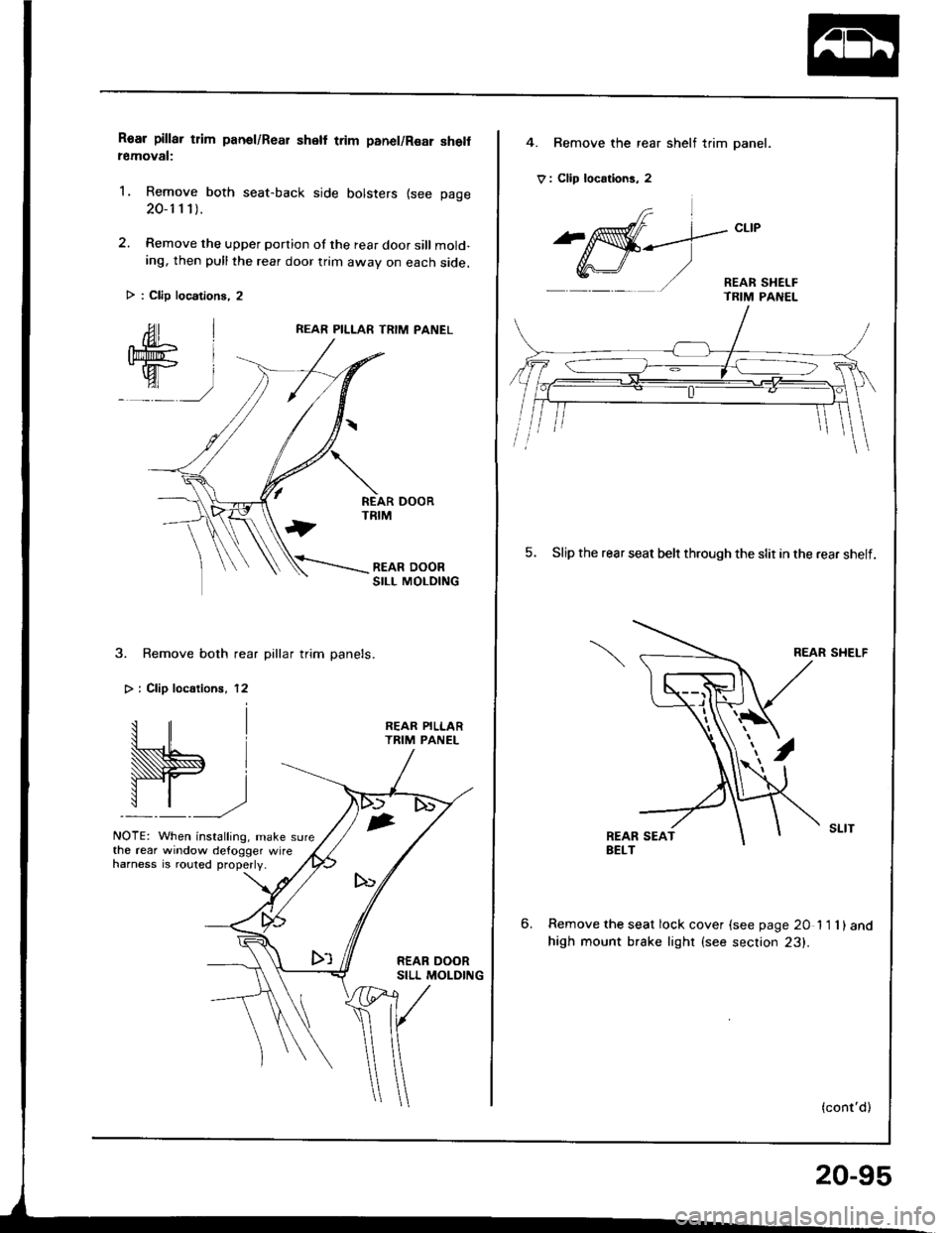
1. Remove both seat-back side bolsters {see page
20-1 1 1).
2. Remove the upper portion of the rear door sill mold-ing, then pull the rear door trim awav on each side.
REAR PILLAR TRIM PANEL
3. Remove both rear pillar trim panels.
> i Clip localionr, 12
W.,
NOTE: When installing, make sure
REAR PILLARTRIM PANEL
the rear window defogger wireharness is .outed properly.
> : Clip locations, 2
4. Bemove the rear shelf trim panel.
V : Clip locrtions, 2
frl
^affi-_--.]-"t't
Y,r\-J/ '/ - REAR sHEr-F- TRIM PANEL
5. Slip the rear seat belr through the slit in the rear shelf.
REAR SHELF
6.Remove the seat lock cover {see page 20 11 1)and
high mount brake lighr (see section 23).
(cont'd)
20-95
Page 1001 of 1413
Dashboard
Component Removal/lnstallation (cont'dl
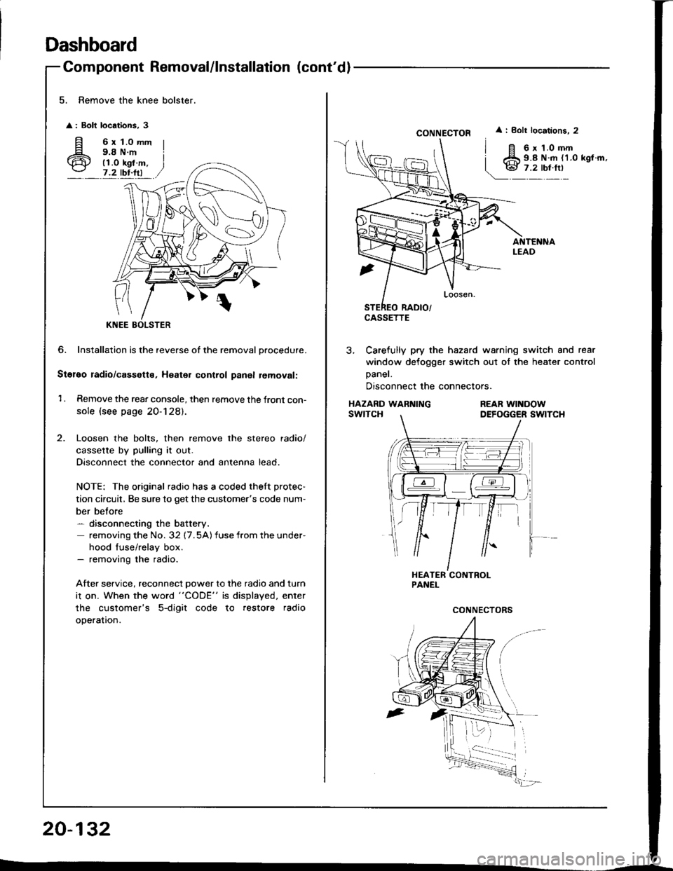
5. Remove the knee bolster.
: Bolt locations, 3
fi 6rt.omm
6 i;i'i#.,7.2 tbr.ftl
?
KNEE
6. Installation is the reverse of the removal Drocedure.
Stol€o radio/cassette, Heater control panal removal:
1 . Remove the rear console, then remove the front con-
sole (see page 20-128).
Loosen the bolts, then remove the stereo radio/
cassette by pulling it out.
Disconnect the connector and antenna lead.
NOTE: The original radio has a coded theft protec-
tion circuit, Be sure to get the customer's code num-
ber belore- disconnecting the battery.
removing the No. 32 17.5A) fuse from the under-
hood fuse/relay box.- removing the radio.
After service, reconnect power to the radio and turn
i1 on. When the word "CODE" is displayed. enter
the customer's 5-digit code to restore radio
operation.
20-132
CONNECTOR
CASSETTE
i Bolt locations. 2
6 x 1.0 mm9.8 N.m {1.0 kgl.m,
3, Carefully pry the hazard warning switch and rear
window defogger switch out of the heater control
Daner.
Disconnect the connectors.
HAZARD WARNINGswtTcHREAR WINOOWDEFOGGER SWITCH
Page 1019 of 1413
Trunk Lid
Replacement (cont'dl
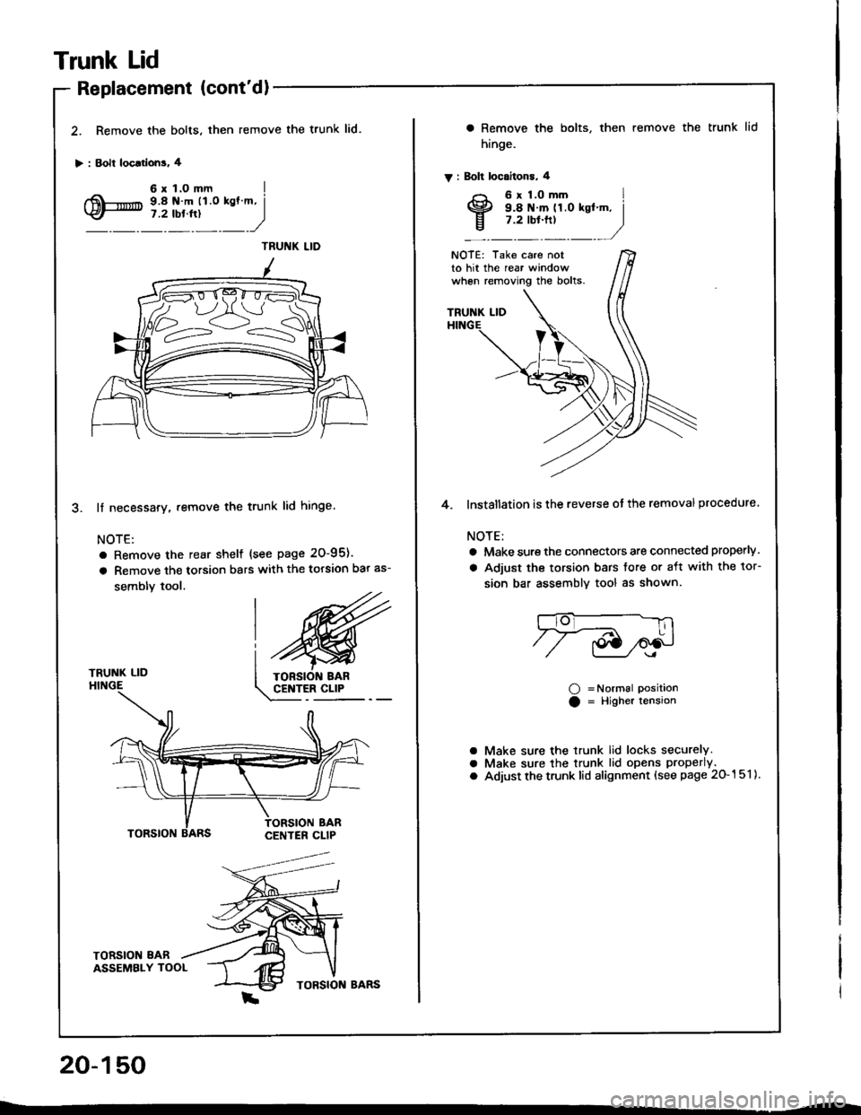
2. Remove the bolts. then
> : Bolt loc.rlons. 4
remove the trunk lid.
TRUNK LIDHINGE
lf necessary. remove the trunk lid hinge
NOTE:
a Remove the rear shelf {see page 20-95).
a Remove the torsion bars with the torsion bar as-
sembly tool.
TORSION 8ABASSEMBLY TOOL
20-150
a Remove the bolts,
hinge.
V : Bolt locaitons, 4
then remove the trunk lid
NOTE: Take care notto hit the rear windowwhen removing the bolts.
TRUNK LID
4. lnstallation is the reverse ot the removal procedure.
NOTE:
a Make sure the connectors are connected properly.
a Adjust the torsion bars tore or aft with the tor-
sion bar assemblv tool as shown.
O =Normal PositionO = Higher tension
Make sure the trunk lid locks securely.Make sure the trunk lid opens properly.
Adjust the trunk lid alignment (see page 20-151).
aaO
Page 1062 of 1413
Defroster Door Adjustment
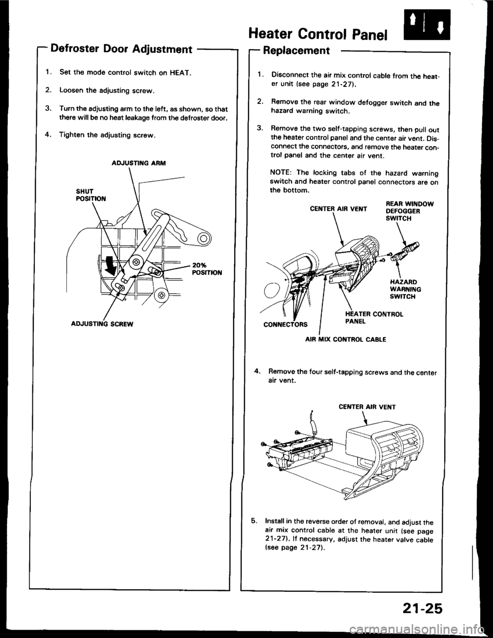
Set the mode control switch on HEAT.
Loosen the adiusting screw.
Turn the adjusting arm to the left, as shown, so that
there will be no heat leakage from the defroster door,
Tighten the sdjusting screw.4.
CE]TTER AIR VEI{T
4. Remove the four self-tapping screws and the centerair v€nt.
Install in the reverse order of removal. and adjust theair mix control cable at the heater unit lsee page21-27). lf necessary, adjust the heater valve cablelsee page 21-27).
REAR WITIDOWDEFOGGERswtTcH
Heater Control Panel
Replacement
Disconned the air mix control cable from the heat-er unit lsee page 21-271.
Remove the rear window defogger switch and thehazard warning switch.
Remove the two self-tapping screws, then pull outthe heater control panel and the center air vent. Dis-connect the connectots, and remove the heater con-trol panel and the center air vent.
NOTE: The locking tabs of the hazard warningswitch and heater control panel connectors are onthe bottom.
AD.'USTII{G ARM
ADJUSTI G SCREW
AIR MIX CONTROL CABLE
CENTEB AIR VE T
21-25