window HONDA INTEGRA 1994 4.G Repair Manual
[x] Cancel search | Manufacturer: HONDA, Model Year: 1994, Model line: INTEGRA, Model: HONDA INTEGRA 1994 4.GPages: 1413, PDF Size: 37.94 MB
Page 1329 of 1413
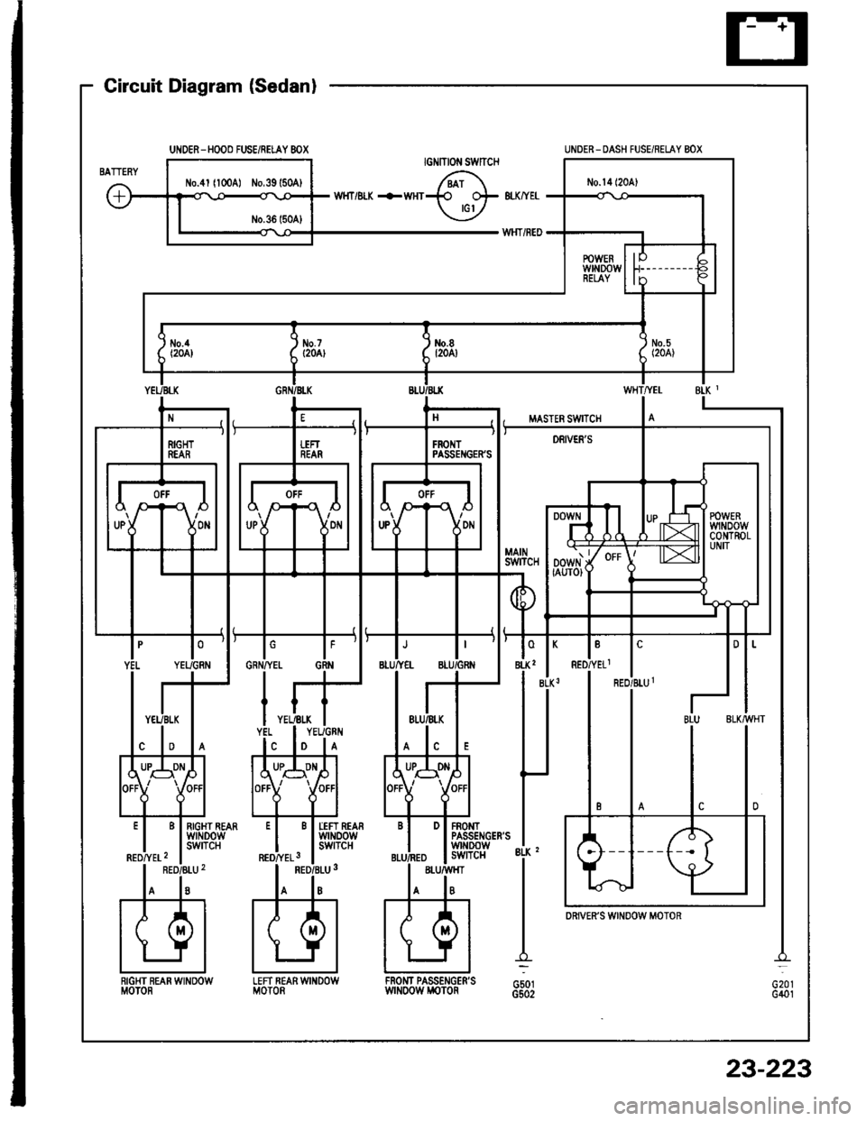
UNOER-HOOO FUSE/RELAY 8OX
Circuit Diagram (Sedanl
G20rG401
UNDER_ DASH FUSE/RELAY BOX
LEFT REARWINDOWMOTORRIGHT REAN WINOOWMOTORFROI{T PASSENGER'SwrNoow i,roToRG501G502
DRiVER'S WINOOW MOTOR
23-223
Page 1330 of 1413
![HONDA INTEGRA 1994 4.G Repair Manual Power Windows
Circuit Diagram (Hatchback)
UNDER - HOOD FUS€/REI.AY BOX
tlo.41 l100Al ilo.39 {50A)
UNOER- OASH FUSE]NEI.AY 8OX
8LX z
G50tG502
D PASSENGERSwrNDowswITcH
PASSENGENSwtN00w M0T0nG401
23- HONDA INTEGRA 1994 4.G Repair Manual Power Windows
Circuit Diagram (Hatchback)
UNDER - HOOD FUS€/REI.AY BOX
tlo.41 l100Al ilo.39 {50A)
UNOER- OASH FUSE]NEI.AY 8OX
8LX z
G50tG502
D PASSENGERSwrNDowswITcH
PASSENGENSwtN00w M0T0nG401
23-](/img/13/6067/w960_6067-1329.png)
Power Windows
Circuit Diagram (Hatchback)
UNDER - HOOD FUS€/REI.AY BOX
tlo.41 l100Al ilo.39 {50A)
UNOER- OASH FUSE]NEI.AY 8OX
8LX z
G50tG502
D PASSENGER'SwrNDowswITcH
PASSENGEN'SwtN00w M0T0nG401
23-224
Page 1331 of 1413
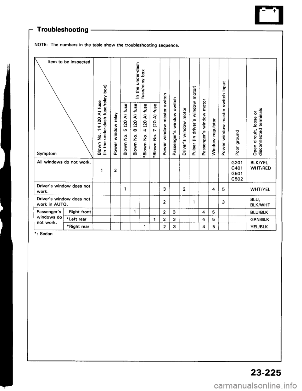
Troubleshooting
NOTE: The numbers in the table show the troubleshooting sequence
Item to be insoected
Symptom
3E
<.i
SHr!
z)
t59c
-g
i
t
o;
o-
o10x
9I
.='
E
!
t
qti
o-
3
I
t
o
oo
o
E
3
t
o
o
E
3
;
=
()Iao-
-
E
3
t
o
o-
x
.9
i
.E
;
.=;
E
3
-
3
:!
g3'.c
OE
,iz
i
6
o
oSJ@
z
3
6
o
N
oz
-
6
(t
N
F\
;z
io
All windows do not work.G20 r
G401
G50l
G502
BLK/YEL
WHT/RED
Driver's window does notI45WHT/YEL
Driver's window does not
work in AUTO.1BLU,
BLK/WHT
Passengsr's
windows do
not work.
Right tront15BLUi BLK
*Lett rear34GRN/BLK
r Right rea.I24YEL/BLK
23-225
Page 1332 of 1413
Power Windows
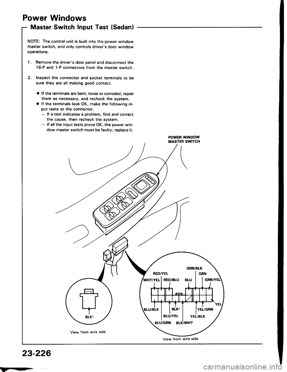
Master Switch Input Test (Sedan)
NOTE; The control unit is built into the Dower window
maste. switch, and onlv controls driver's door window
ooerations.
1. Remove the driver's door panel and disconnect the
16-P and 1-P connectors from the master switch.
2. Inspect the connector and socket terminals to be
sure they are all making good contact.
a lf the terminals are bent, loose or co.roded, reDair
them as necessary. and techeck the system.a It the terminals look OK, make the following in-
put tests at the connecto..- It a test indicates a problem, tind and correct
the cause, then recheck the system.- lf allthe input tests prove OK, the power win-
dow master switch must be faulty; replace it.
23-226
BEDI'EL I GRN
8LU/YEL I YEL/BLK
View from wire side
View lrom wire side
Page 1333 of 1413

Test conditionT€st: Desirod rosultPossibl€ cause if result is not obtainad
BLK2
ano
BLK3
Under all conditionsCheck for continuity to ground:
There should be continuitv,
. Poor ground {c501, G502). An open in the wire
WHT/YELlgnition switch ON (lllCheck for voltage to ground:
The.e should be battery voltage.
Blown No. 14 (20 Al fuse in the
under-dash fuse/relay box
Bfown No. 5, 8, 7 ot 4 l2O Al fuse
in the under-dash fuse/relay box
Faulty power window relay
An open in the wire
BLU/BLK
GRN/BLK
YEL/BLK
RED/BLU1
ano
REDATELl
Connect the WHT/YEL
and RED/YEL1 terminals,
and the RED/BLU1 and
BLK3 terminals with jum-
per wires, then turn the
ignition switch ON (lll.
Check the driver's window
motor:
It should run (the window
moves down).
. Faulty drivea's window motor. An open in the wire
4
BLU/YEL
and
BLU/GRN
Connect the BLU/BLK
and BLU/GRN terminals,
and the BLU/YEL and
BLK, terminals with jum-
per wires, then turn the
ignition switch ON (ll).
Check the tront passenger's
window motor:
It should run {the window
moves down).
. Faulty front passenger's window
motOa. An open in the wire
5
GRN/YEL
ano
GRN
Connect the GRN/BLK
and GRN terminals, and
the GRN/YEL and 8LK,
terminals with iumperwires, then turn the igni-
tion switch ON (ll).
Check the left fear window
motor:
It should run (the window
moves down).
Faulty left rear window motof
Faulty lett rear window switch
An oDen in the wire
6
YEL/GRN
and
YEL
Connect the YEL/BLK
and YEL/GRN terminals,
and the YEL and BLK,
terminals with iumper
wires, then turn the igni-
tion switch ON (ll).
Check the right rear window
motor:
It should run (the window
moves down).
Faulty .ight rea. window motor
Faulty right rear window switch
An open in the wire
7
BLU
ano
BLK/VVHT
Connect the WHT/YEL
and RED/YEL1 terminals.
and the REo/BLU1 and
BLK3 terminals with jum-
per wires. then turn theignition switch ON (ll).
Conned an analog ohmmeter tote.minals BLU and BLK/wHT:
The meter needle should move
back and lorth alternatelv asthe driver's window motor runs.
Faulty pulser
Faulty driver's window motor
An open in the wire
23-227
Page 1334 of 1413
Power
Master
Windows
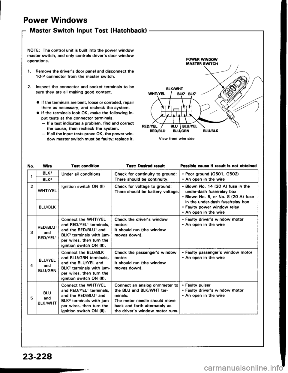
Switch lnput Test(Hatchback)
NOTE: The control unit is built into the power window
master switch, and onlv controls driver's door window
operations,
1. Remove the driver's door panal and disconnect the
1O-P connectol from the master switch.
2. lnsDect the connector and socket terminals to be
sure they are all making good contact.
a lf the terminsls arc bent, loose or corroded, rspair
them as necessary, and recheck the system.
a lf the terminals look OK, make the following in-
put tests at the connector terminals.- lf a test indicates a problem, find and correct
the cause, then recheck the systsm.- lf all the input tests prove OK, the powsr win-
dow master switch must be faulty; replace it.
RED/YEL
RED/BLUBLU/GR'{BLU/BLK
View from wirs sido
WiroTost conditionTost: Dashod r€suhPGslblo cluso if rosuh ir not obtalnad
1BLK'Under all conditionsCh€ck for continuity to ground:
There should be continuity.
Poor ground (G501, G5O2)
An oDen in the wire8LK3
WHT/YELlgnition switch ON {ll)Ch6ck for voltags to ground:
Th€re should be battery voltage.
Blown No. 14 l2O Al fuse in the
under-dash fuso/relay box
Blown No. 5, or No. 8 (2O A) tuse
in the under-dash luse/relay box
Faulty power window relay
An oDen in the wire
BLU/BLK
RED/BLU1
ano
RED/YELI
Connect the WHT/YEL
and REDfYELI terminals,
and the RED/BLU1 and
BLK3 terminals with jum-
per wires, then turn the
ignition switch ON {ll).
Check the driver's window
motor:
It should run (the window
moves down).
. Faulty driver's window motor. An ooen in th€ wire
4
BLU/YEL
and
BLU/GRN
Connect the BLU/BLK
and BLU/GRN terminals,
and the BLUTYEL and
BLK2 terminals with jum-
per wires, then turn the
ignition switch ON {ll).
Check ths passengor's window
motor:
It should run (the window
moves down).
. Faulty pass€nger's window motor. An oD€n in the wire
5
BLU
anq
BLKMHT
connect the WHTTYEL
and BEDrYELI terminals,
and the RED/BLU1 and
BLK3 terminals with jum-
pe. wires, then turn the
ignition switch ON (ll).
Conn€ct an analog ohmmeter to
thE BLU ANd BLKMHT t€Tr
minals:
The meter needle should move
back and torth alternately as
th€ driver's window motor runs.
Faulty pulser
Faultv driver's window motor
An oDen in the wire
23-228
Page 1336 of 1413
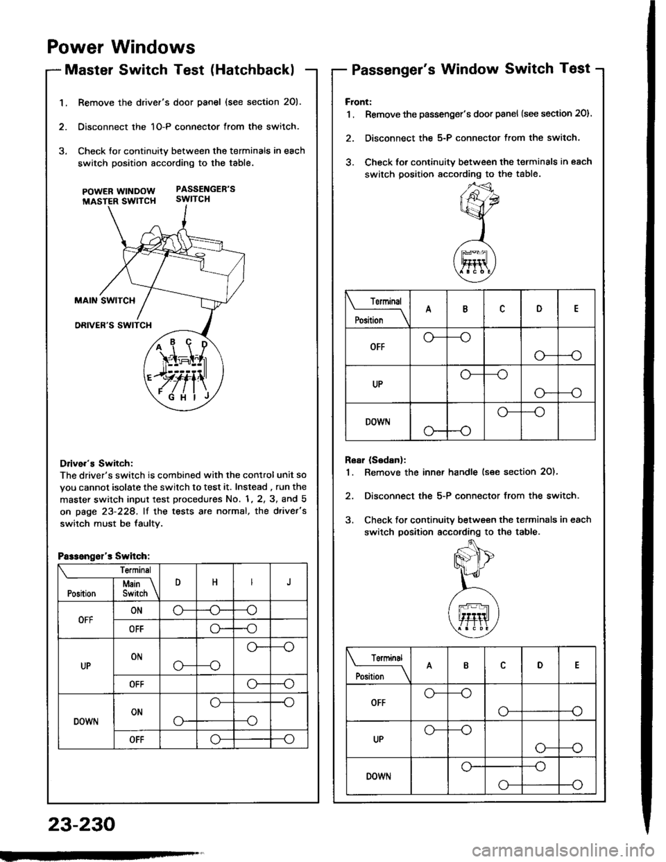
1.Remove the drivef's door panel (see section 201.
Oisconnect the 1O-P connector from the switch.
Check tor continuity between the terminals in each
switch position according to the table.
pOWERWTNDOW PASSENGEB'S
MASTER SWTTCH SWITCH
Drive.'s Switch:
The driver's switch is combined with the control unit so
you cannot isolate the switch to test it. Instead , run the
master switch input test procedures No. 1, 2, 3, and 5
on page 23-228, lf the tests are normal, the d.ivet's
switch must be faultv.
i1\i
\4r-I^l,r
)rvti\
.Fi'ilj
Passengsl'r Switch:
Te.minsl
DHJI Msin \Position I Switch \
OFFONo-(J--o
OFFo--o
UPONo---o
o--
OFFo--o
DOWNONo-
o--o
--o
OFFo--o
Power Windows
Master Switch Test (HatchbacklPassenger's Window Switch Test
23-230
Front:
1 . Remove the passenger's door panel {see section 20).
2. Disconnect the 5-P connector from the switch.
3. Check for continuity between the terminals in each
switch position sccording to the table.
Rear (Sedanl:
1. Remove the inn€r handle (see section 2O)'
2, Disconnect the 5-P connector from the switch.
3. Check for continuity between the terminals in each
switch position according to the table.
Torminal
il;_\
ARD
OFFo-
--o
UPo---o
G_--o
DOWr.lo---o
Terminal
;;__\ID
OFFG_--o
o---o
UPG_--o
o---o
DOWNo---o
o-
Page 1337 of 1413
Master Switch ReplacementPassenger's Window Switch
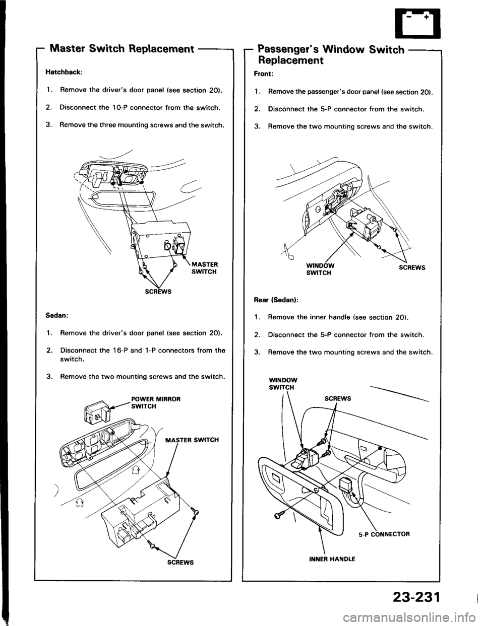
Hatchback:
1. Remove the driver's door panel (see section 20).
2. Disconnect the 1O-P connector lrom the switch,
3, Remove the three mounting screws and the switch.
Sedan:
1. Remove the driver's door panel (see section 2O).
2. Disconnect the 1 6-P and 1-P connectors from the
switch.
3. Remove the two mounting screws and the switch.
POWER MIRRORswtTcH
scREws
Replacement
Flont:
1 . Remove the passenger's door panel (see section 201.
2. Disconnect the 5-P connector from the switch.
3. Remove the two mounting screws and the switch.
Roar (S6danl:
1. Remove the inner handle (see section 20).
2. Disconnect the 5-P connector from the switch.
3. Remove the two mounting screws and the switch.
w|I{Dow.swtTcH
swtTcl{
INNER HANDLE
23-231
Page 1338 of 1413
Power Windows
Driver's Window MotorTest
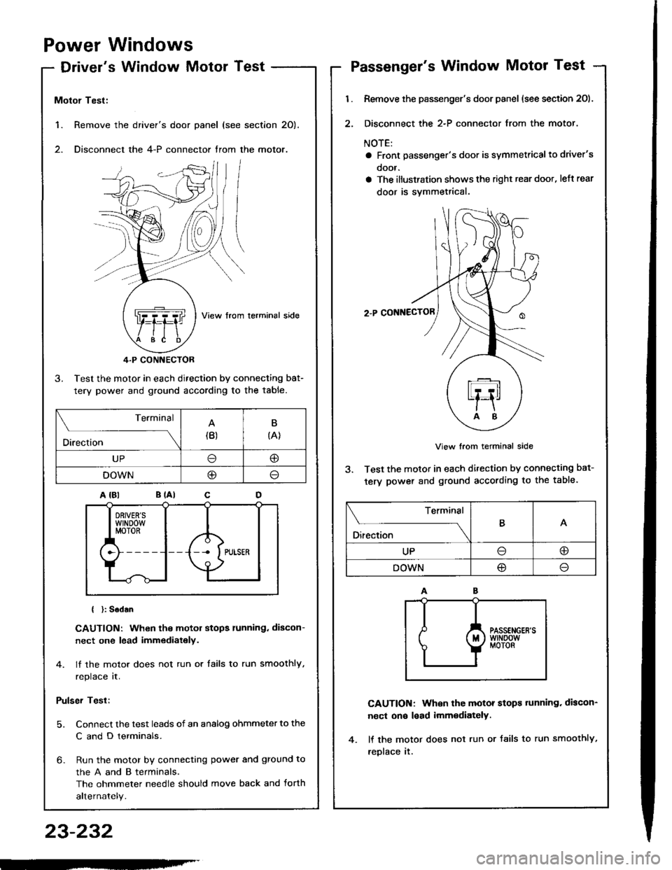
1. Remove the
2. Disconnect
Motor Test:
View from lerminal side
4.P CONNECTOR
3. Test the motor in each direction by connecting bat-
tery power and ground according to the table.
{ }: Sodan
CAUTION: When the motor stops running. discon-
nect one lead immediately.
4. lf the motor does not run or tails to run smoothly,
replace it.
Pulser Test:
5. Connect the test leads of an analog ohmmeter to the
C and D terminals.
6- Run the motor by connecting power and ground to
theAandBterminals,
The ohmmeter needle should move back and torth
alternately.
driver's door panel (see section 20).
the 4-P connector trom the motor.
. ,-,.f,/l l/
NZJI I
..Q]qql ,fiftl I
$e /tE \
Terminal
Direction(B)B
{A}
UP@
DOWNO
Passenger's Window Motor Test
l.
2.
Remove the passenger's door panel (see section 20).
Disconnect the 2-P connector from the motor.
NOTE:
a Front passenger's door is symmetricalto driver's
ooor.
a The illustration shows the right rear doot, left rear
door is svmmetrical.
2.P CONNECTOR
View from terminal side
3. Test the motor in each direction by connecting bat-
tery power and ground according to the table.
CAUTION: When the motor stops tunning. discon-
nect on€ lead imm€diately.
lf the motor does not run or Jails to run smoothly,
reDlace it.
Terminal
O*** \
BA
UPoo
DOWN@
23-232
-'
Page 1360 of 1413
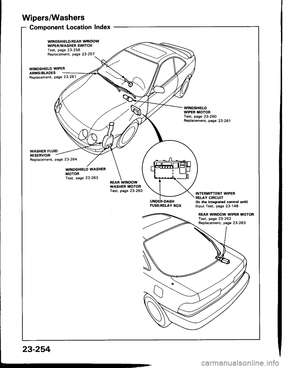
Wipers/Washers
Component Location Index
WII{DSHIELD/REAR WINDOWWIPERAA'ASHEB SWITCHTest, page 23-258Replacement, oase 23 257_..
wtNosHlELD WIPER 2ARMS/BLADES ___-=4,
Repfacemont, Page 23'261 /tt' /
WINOSHIELDIVIPER MOTORTest, page 23-260Repfacement, paee 23-281
FUSE/RELAY BOX
INTERMITTENT WIPERBELAY CIRCUIT(ln the int€gral.d control onitlInput Test, page 23-146
REAR WII{DOW WIPER MOTORTest, page 23-262Replacemont, pago 23-263
23-254