ABS HONDA INTEGRA 1994 4.G Owner's Manual
[x] Cancel search | Manufacturer: HONDA, Model Year: 1994, Model line: INTEGRA, Model: HONDA INTEGRA 1994 4.GPages: 1413, PDF Size: 37.94 MB
Page 669 of 1413
Steering Gearbox
Reassembly (cont'dl
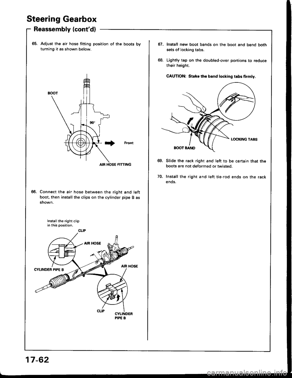
65. Adjust the air hose fitting position of the boots by
turning it as shown below.
Front
AIR HOSE FITTING
Connect the air hose between the right and left
boot. then install the clips on the cylinder pipe B assnown.
Install the right clipin this position.
CLIP
17-62
67.Install new boot bands on the boot and bend both
sets of locking tabs.
Lightly tap on the doubled-over portions to reduce
their height.
GAUTION: Stake tho band locking tabs firmly.
Slide the rack right and left to be certain that the
boots are not detormed or twisted.
Install the right and left tie-rod ends on the rack
ends.
70.
Page 1009 of 1413
Bumpers
Front Bumper RePlacement (cont'd)
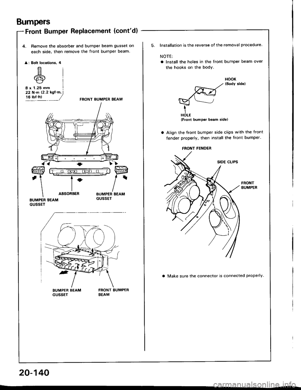
4. Remove the absorber and bumper beam gusset on
each side. then remove the front bumper beam.
: Eolt locotions. 4
E6rcr
8 r 1.25 mm
22 N.m (2.2 kgt'm, I't6 tbt fti _/FRONT BUMPER BEAM
ABSORBER
20-140
FRONT FEiIDER
Installation is the reverse of the removal procedure.
NOTE:
o Install the holes in the front bumper beam over
the hooks on the bodY.
FrBo*sidorHOLE(Front bumper b€am sidel
Align the front bumper side clips with the tront
fender properly, then install the front bumper.
FRONTBUMPER
a Make sure the connector is connected properly.
Page 1011 of 1413
Bumpers
Rear Bumper Replacement (cont'dl
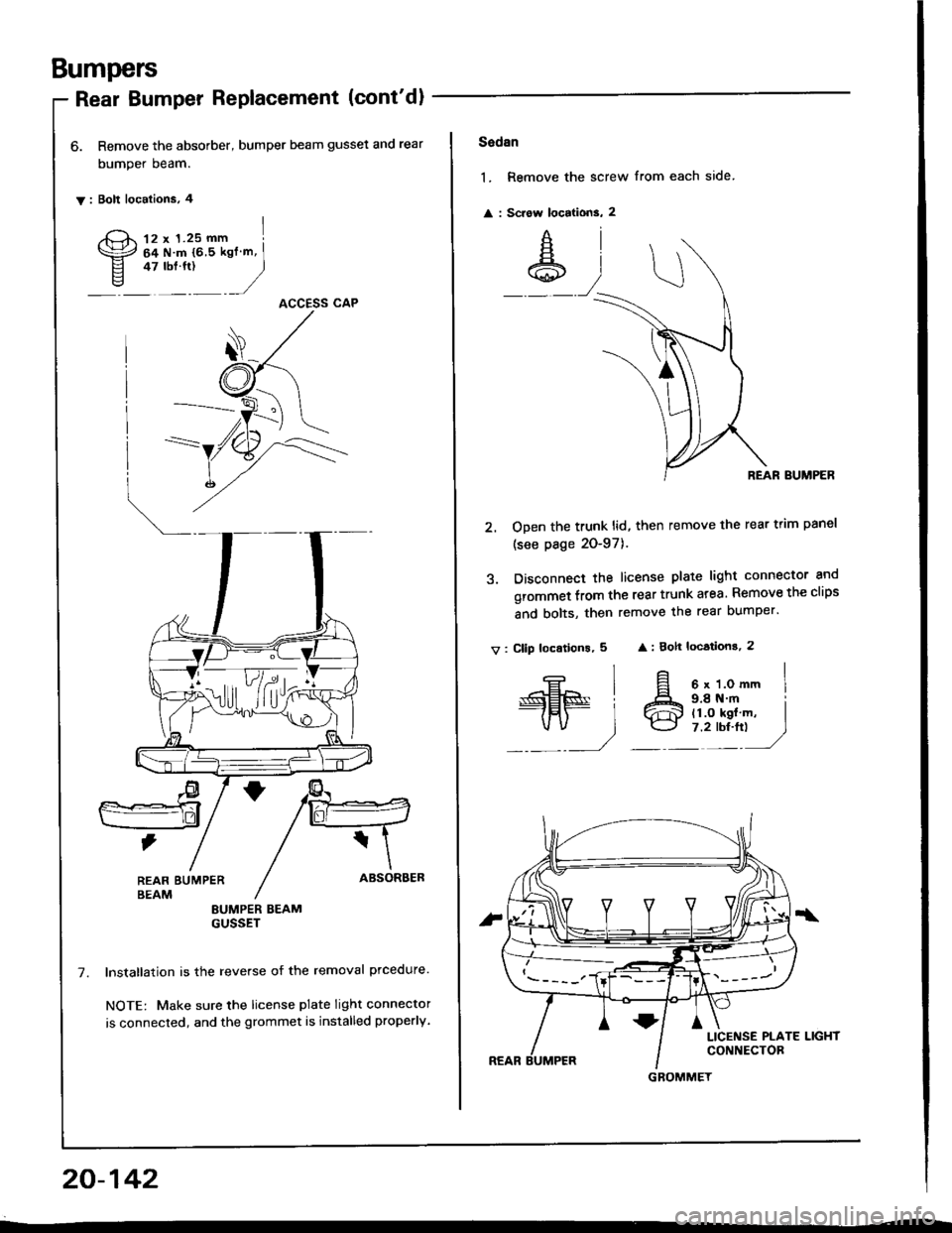
6. Remove the absorber, bumper beam gusset and rear
bumper beam.
y: Bolt localions, 4
12 x 1.25 mm I
64Nm{65kgfm,I* "r:,
)ACCESS CAP
LlF/d,rft
REAR EUMPERBEAMEUMPER BEAMGUSSET
lnstallation is the reverse of the removal prcedure.
NOTE: Make sure the license plate light connector
is connected, and the grommet is installed properly,
20-142
Sadan
1. Remove the screw from each side
: Sciow locations, 2
REAR BUMPER
2. ODen the trunk lid, then remove the rear trim panel
(see page 20-97).
3. Disconnect the license plate light connector and
grommet from the rear trunk atea. Remove the clips
and bolts, then remove the rear bumper'
v: Cllp loc.tions, 5 : 8ok locations, 2
€l
#.,1
9.8 N.m il1.O kgl m, I7.2 rbr.ft) J
6 x 1.0 mm I
GBOMMET
Page 1012 of 1413
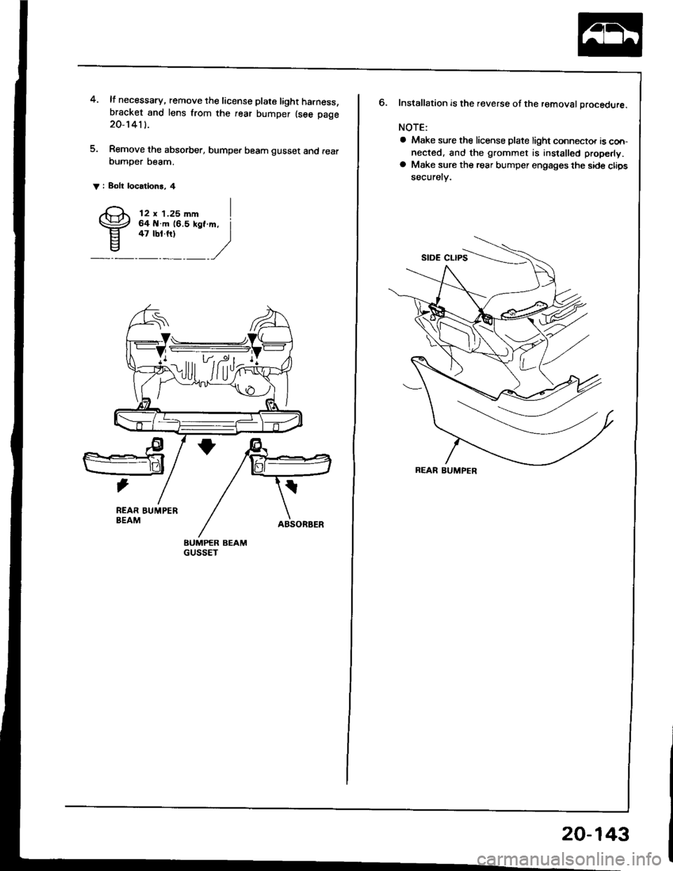
4. lf necessary, remove the license plate light harness,bracket and lens from the rear bumper (see page20-1411.
5. Remove the absorb€r, bumper beam gusset and fearbumper beam.
V i Bolt locatlons, 4
REAR BUMPERBEAM
BUMPER BEAMGUSSET
12 x 1.25 mm64 .m (6.5 kgf47 tbt.ftl
I.m, j
)
6. Installation is the .everse of the removal procedure.
NOTE:
a Make sure the license plate light connector is con-
nected, and the grommet is installed properly.
a Make sure the rear bumper engages the side clips
securelv.
REAR BUMPER
20-143
Page 1062 of 1413
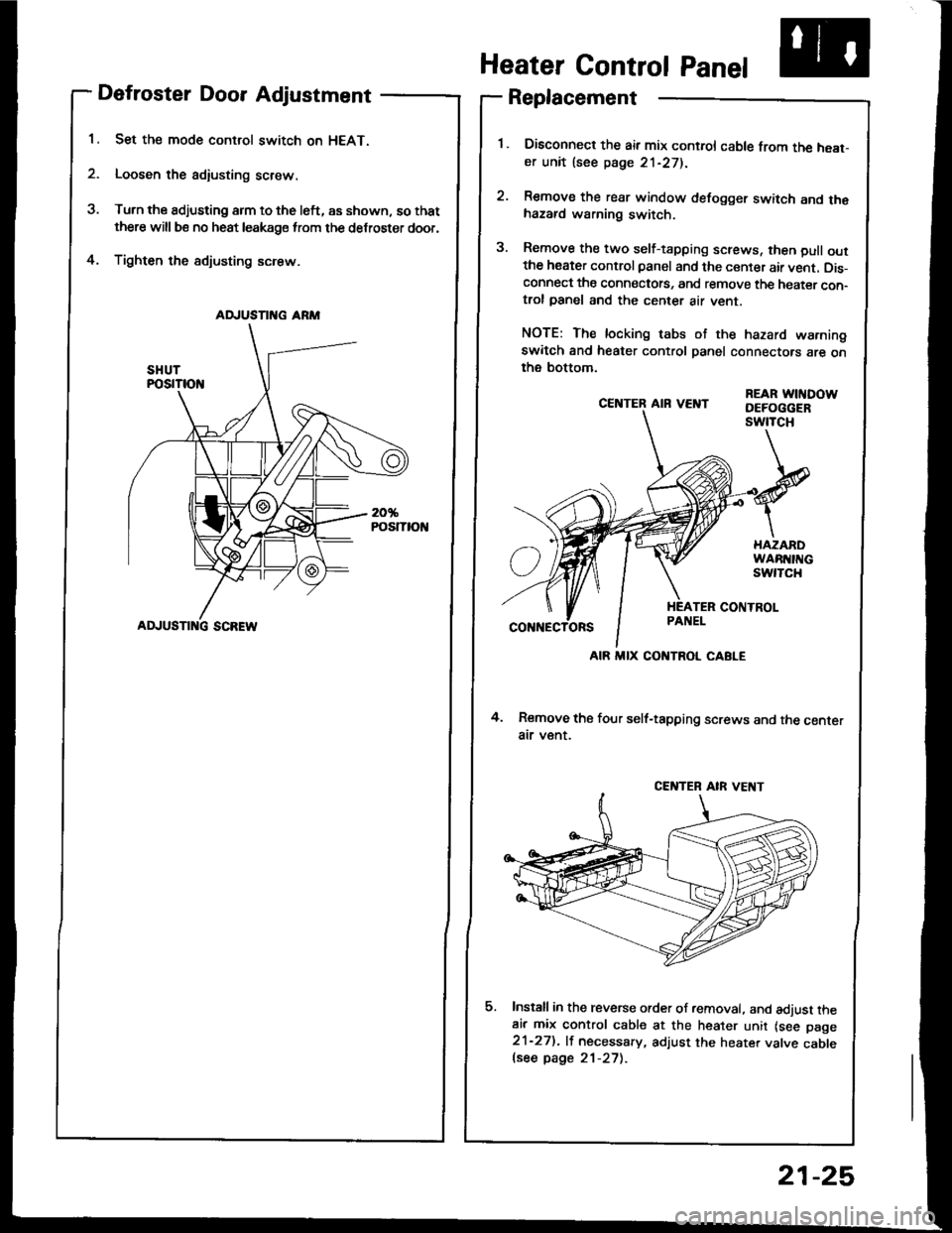
Defroster Door Adjustment
Set the mode control switch on HEAT.
Loosen the adiusting screw.
Turn the adjusting arm to the left, as shown, so that
there will be no heat leakage from the defroster door,
Tighten the sdjusting screw.4.
CE]TTER AIR VEI{T
4. Remove the four self-tapping screws and the centerair v€nt.
Install in the reverse order of removal. and adjust theair mix control cable at the heater unit lsee page21-27). lf necessary, adjust the heater valve cablelsee page 21-27).
REAR WITIDOWDEFOGGERswtTcH
Heater Control Panel
Replacement
Disconned the air mix control cable from the heat-er unit lsee page 21-271.
Remove the rear window defogger switch and thehazard warning switch.
Remove the two self-tapping screws, then pull outthe heater control panel and the center air vent. Dis-connect the connectots, and remove the heater con-trol panel and the center air vent.
NOTE: The locking tabs of the hazard warningswitch and heater control panel connectors are onthe bottom.
AD.'USTII{G ARM
ADJUSTI G SCREW
AIR MIX CONTROL CABLE
CENTEB AIR VE T
21-25
Page 1074 of 1413
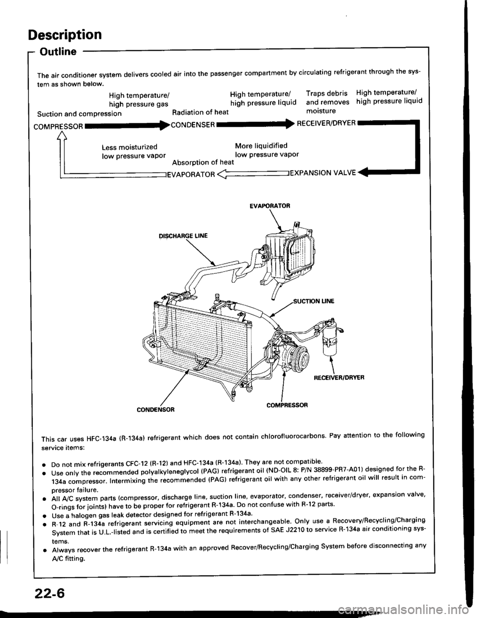
Description
Outline
The air conditioner system delivers cooled air into the passenger compartment by circulating refrigerant through the sys-
tem as shown below.
CONDENSOR
This car uses HFC-134a {R-134a) refrigerant which does not contain chlorofluorocarbons Pay attention to the following
service items:
. Do not mix refrigerants CFC-I2 (R-l21 and HFC-134a (R-134a) They are not compatible'
. Use onty the recommended potyatkytenegtycol {PAG) refrigerant oil (ND-OIL 8: P/N 38899-PR7-A01) designed for the R-
134a compressor. Intermixing the recommended (PAG) refrigerant oil with any other refrigerant oil will result in com-
pressor tailure.
.A||lvcsystemparts(compressor.dischargeIine,suotionIine,evaporator,condenser.receiver/dryer,expansionva|ve.
o-ringsforioints}havetobeproperforre'rigerantR-l34a.DonotconfusewithR.l2parts.
. Use a halogen gas leak detector designed for refrigerant R-134a'
. R-.12 and C-l34a refrigerant servicing equipment are not interchangeable. Only use a Recovery/Recyclins/Charging
System that is U.L.-listed and is certifLd to meet the requirements of sAE J2210 to service R-134a air conditioning sys-
rems.
. Always recover the refrigerant R-134a with an approved Recover/Recycling/Charging System before disconnecting any
A,/C fitting.
coMpRESsoR -coNDENSER - RECEIVER/DRYER
High temperature/
high pressure gas
Suction and comPression
Less moisturized
low pressure vaPor
High temperature/ Traps debris High temperature/
hilh pressure liquid and removes high pressure liquid
Radiation of heat molsture
More liquidified
low Pressure vaPor
Absorption of heat
EVAPORATOR <-'----------.- EXPANSION VALVE
EVAFORATOR
22-6
Page 1089 of 1413
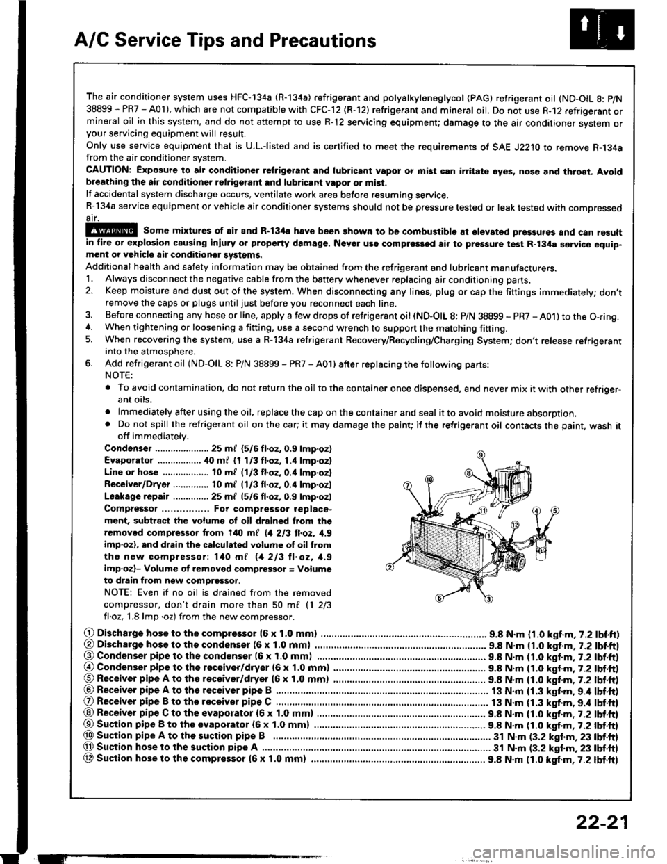
A/C Service Tips and Precautions
The air conditioner system uses HFC-134a (R-134a) .efrigerant and polyalkyleneglycol (PAG) retrigerant oil (ND-OIL g: p/N
38899 - PR7 - A0l ), which are not compatible with CFC-12 \R-'12) refrigerant and mineral oil. Do not use R-12 refrigerant ormineral oil in this system, and do not attempt to use R-'12 servicing equipment; damage to the air conditioner system oryour servicing equipment will result.
only use service equipment that is u.L,-listed and is certified to meet the requirements of sAE J2210 to remove R-134afrom the air conditioner svstem.
CAUTION: Exposure lo air conditioner refrigorant and lubricanl vapor or mi3t cln irritato gyos, nose and throat. Avoidbreathing lhe air conditioner refrigerant and lubricant vapor or mist.
lf accidental system discharge occurs, ventilate work area befor€ resuming service.R-134a service equipment or vehicle air conditioner systems should not be pressure tested or leak tested with compressedair.
@ some mirtures of air and R-l3ifa have been 3hown to be combu3tible at slsvated prossuros and can relultin fire or explosion causing inlury or property damage. Never use complessod ai. to prgssure t€|st R-134a service equip-ment or vehicle air conditiongr systems.
Additional health and safety information may be obtained from the refrigerant and lubricant manufacturers.'1. Always disconnect the negative cable from the battery whenever replacing air conditioning pans.
2. Keep moisture and dust out of the system. When disconnecting any lines, plug or cap the fittings immediately; don'tremove the caps or plugs until just before you reconnect each line.
3. Before con necting a ny hose or line, apply a few drops of refrigerant oil (ND-OIL 8: P/N 38899 - PR7 - AO1) to the O-ring.4. When tightening or loosening a fitting, use a second wrench to support the matching fitting.5. When recovering the system, use a R-134a refrigerant Recovery/Recycling/Charging System; don't release refrigerantinto the atmosDhere.
6. Add refrigerant oil (ND-OlL 8: P/N 38899 - PR7 - A01) after replacing the following parts:
NOTE:
. To avoid contamination, do not return the oil to the container once dispensed, and never mix it with other refriqer-ant orls.
. lmmediately after using the oil, replace the cap on the container and seal ittoavoid moisture absorption,. Do not spill the refrigerant oil on the car; it may damage the paint; if the re{rigerant oil contacts the paint, wash itoff immediately.
Condenser ..................... 25 m/ (5/6 fl.oz, 0.9 lmp.oz)
Evaporator ................. ilo mf 17 113fl.oz,1.4 lmp.oz)
Line or hose 10 ml (1/3 fl.oz. o.il lmp'ozl
Receiver/Dryer .....,.,,...., 10 m{ l1l3 tl.oz, 0.4 lmp.ozl
Leakage repair .............. 25 mf (5/6 fl.oz, 0.9 lmp.ozl
Compressor For compressor .eplaco-
m€nt, subtract the volumo of oil drained from tho
removed compressor trom 140 ml 11 213 ll.oz, 1,9
imp.ozl, and drain the calculalgd volume of oil from
tho new compressor: 140 mf 11 213 ll. oz, 1.9
imp.ozl- Volume ot removod compressor = Volume
to drain from n€w compressor.
NOTE: Even if no oil is drained from the removed
compiessor, don't drain more than 50 ml 11 213
fl.oz, 1.8 lmp .oz) from the new comDressor.
O Dischargo hose to the compresso. (6 x 1.0 mml .............................. 9.8 N.m {1.0 kgt.m, 7.2 lbf.ft)(, Discharge hosa to ths condenser (6 x 1.0 mm) . 9.8 N.m {1.0 kgf.m, j.Z lbl.ftl@ Condenser pipe to tho condenser (6 x 1.0 mml 9.8 N.m n.O kaf.m,t-2tbl.ftl
@ Condenser pipe to the receiver/dryer (6 x 1.0 mm) ......................... 9.8 N.m (1.0 katm,7.2 lbf.ft)@ Receiver pipe A to tho receiver/dryer 16 x 1.0 mm) ......................... 9.8 N.m (1.0 kttm. 7.2 lbt.ft)@ Receiver pipe A to th6 receiver pipe B ......................................
O Receiver pipe B to the receiver pipe C .............................................. 13 N.m {1.3 kgt.m. 9.4 lbt'ft)
13 N.m {1.3 kgf.m.9.4 lbf'ft)@ Receiver pipe C to the evaporator (6 x 1.0 mm) 9.8 N.m {1.0 kgf.m , j.Zlbl.ftl
@Suaion pip€ B to the evaporator {6x 1.0 mm) ................ ................ 9.8 N.m tt.O t!f.-, r.Z tUt tt}@ Sustion pipe A to the suction pipe B .................. 3t N.m (3.2 klnm,23 lbf.ft)(, Suction hose lo the suction pipe A ................ ...... 31 N.m (3.2 kgf.m, 23 tbf.ftl
OA Suction hose to the compressor {5x 1.0 mm} ................ ................. 9.8 N.m 11.0 kgt.m,7.2 lbf.ft)
ET
22-21
Page 1100 of 1413
and com
it with a
a
a
a
a
4t l\-N
r-
-l/
Compressor
Clutch Overhaul (cont'dl
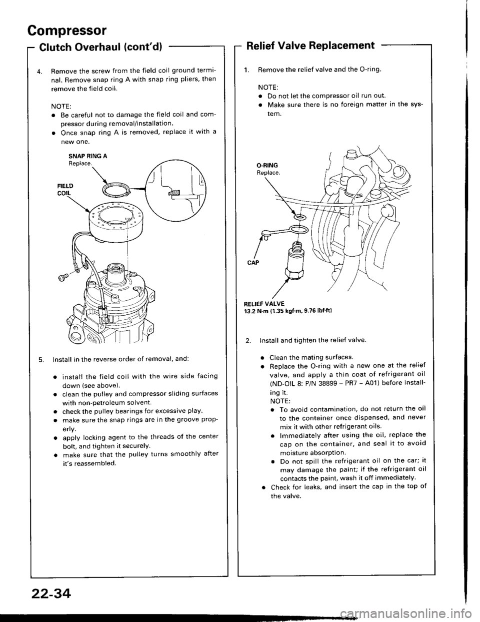
Remove the screw from the field coil ground terma-
nal. Remove snap ring A with snap rjng pliers, then
remove the field coil.
NOTE:
. Be careful not to damage the field coil
pressor during removal/installation.
. Once snap ring A is removed, replace
new one.
SNAP RING AReplace.
FIELDcorL
5. lnstall in the reverse order of removal, and:
install the field coil with the wire side facing
down (see above).
clean the pulley and compressor sliding surfaces
with non-petroleum solvent.
check the pulley bearings for excessive play.
make sure the snap rings are in the groove prop-
efly.
apply locking agent to the threads of the center
bolt, and tighten it securelY
make sure that the pulley turns smoothly after
it's reassembled.
1. Remove the relief valve and the O-ring.
NOTE:
. Do not let the compressor oil run out.
. Make sure there is no foreign matter in the sys-
tem.
RELIEF VALVE13.2 N.m {1.35 kgtm,9.76lbtftl
2. lnstall and tighten the relief valve.
Clean the mating surfaces.
Replace the O-ring with a new one at the relief
valve, and apply a thin coat of refrigerant oal
(ND-OIL 8: P/N 38899 - PR7 - A01) before install-
ing it.
NOTE:
. To avoid contamination, do not return the oil
to the container once dispensed, and never
mix it with other refrigerant oils.
. lmmediately after using the oil, replace the
cap on the container, and seal it to avoid
moisture absorption.
. Do not spill the refrigerant oil on the car; lt
may damage the painu if the refrigerant oil
contacts the paint, wash it off immediately.
Check for leaks, and insert the cap in the top of
the valve.
22-34
Page 1107 of 1413

Electrical
Special Tools
Troubleshooting
Tips and Precautions ................................ 23-3Five-stop Tloubleshooting ..............,...-..-... Z3-sSchematic Symbols ................................_. 23-6wire Color Cod€s ..................................... 23-6Relay and Control Unit Locations
Engine Compartment .........,............ ... --. 23-7Dsshboard and Door ..,,......................... 23-gDashboard and Floor ............................. 23-t OOuaner Panel .....-.....23-12Connector ldentification and WireHarness Routing ........ 23-i 3
Index to Circuits and Systems
Airbag ............... ...-..-... 2g-26sAir Conditioning ....,.. Section 2lAltelnator ......_.............. 23-99Anti-lock Brake Systsm (ABS) Section 19Automatic Transmission Section 14Battery .............. .......... 23-66Chafging System ........... 23-98rCigalstte Lighter .....................-...-......-..-.. Z3-2O4Cfock ................. ..........23-197rcruise Controf .......--..-... 23-242Distributor .................... 23-87Fan Controls ................. 23-1ogFuel and Emissions ... Section 1i*Fuses
Under-dash Fuse/Relay Box ................... 23-48Undor-hood ABS Fuse/Retay Box ............ 23-51Under-hood Fuse/Relay Box,.................. 23-52rGauges
Engine Coolant Temperature {ECT)Gauge ................ ..23-126Fuef cauge ............... 2g-123'Gauge Assembly ....--.23-113Speedometer .....-...,,. 23-114Tachometer .....,.....-.. 23-114Ground Distribution ........ 23-60Heater ,,,........,.... ..... Section 2lrHorn ................. ........... 23-199*fgnition Switch ............. 23-70fgnition Syst6m .......-..-.. 23-A7lgnition Timing .............. 23-89Indicator Lights"A/T Gear Position .............. ................... 23-1 32B1ak6 System ...,..,..-.23-127Engine Oil Pressura .............................. _ 23-1 51Low Fuel ............ ......23-125Malfunction Indicator Lamp {MlL} ...,,. Section I l
tfnteglated Control Unit ...29-144*lnterlock System ...................................... 23-1 3gLights, Exteriol
Back-up Lights ........... 23-179Brake Lights .............. 23-t8ltDaytime Running Lights {Csnada} ........... 23-156Front Palking Lights ............................. 23-1 65Flont Side Marker Lights ....................... 23-165Front Turn Signal Lights ........................ 23-1 65*Hazard Warning Lights .........................- 2g-1A4Headlights ................. 23-t6tLicense Plate Lights .............................. 23-1 69Taillights(Harchback) .......... 23-166
{Sedan) .............. .. 23-167Lights. Inteliol
Cargo Area Light {Hatchback) ...... -.. -.. -... 23-177Ceifing Light ........-..-.23-175
Dash Lights Blightness Controt .............. 23-t70Glove Box Lighr ................................... 23-1 69Spotfighr ............ ....-.23-174Trunk Light (Sedanl ............... .............. - 23.-177*Lighting Sysrem .......-.-... 23-152:Moonroof ,,.,.......,..,,,,,.-.23-211PGM-FI Systom ........ S€crion 11Power Distribution .,.-..--..23-54Power Door Locks .............,,..................... 23-233Power Mirors ..,..,....-...- 23-216Power Relays ...........,..... 23-68Power Windows ............ 29-222*Rear Window Defogger ........,... ..........,..... - 23-20,6Reminder Systems
Key-in Remindel System ....,.............,.... 23-1 50Lights-on Reminder System ................... 23-l 5f*Maintenance Reminder system ..,,.... -.. - -. 23-.1 2gSeat Belt Reminder System ..................- 23-125*Side Markel/Turn Signal/Hazard
Ffasher System .,..,..-.23.-1A4Spark Pfugs .........-...-..... 23-97Starting System ....,,.....-. 23-73*Stereo Sound System ...,.......................,,.. 23-l gg
Supplemental Restraint System {SRS} ......... 23-265Vehicfe Speed Sensor {VSS) .............--..-.... 23-122*Wiper/Washer Systom ...............--.........-..- Zg-254
rRead SRS pi€cautions on Page 23-271 betore workingin these areas.
-+
Page 1110 of 1413
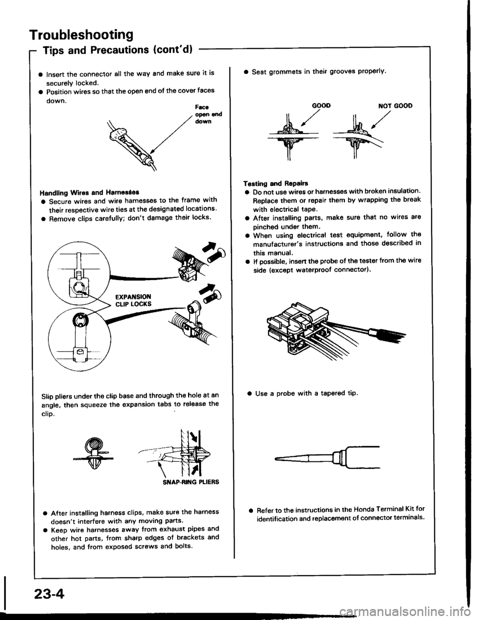
Troubleshooting
Tips and Precautions (cont'dl
a lnsert the connector all the way and make sure it is
securely locked.
a Position wires so that the open end of the cover taces
down.Facaopon andcown
V
Handling Wir€s and Hamorao8
a Secure wires and wile harnesses to the frame with
their respective wire ties at the designated locations'
a Remove clips carefully; don't damage their locks'
Stip pliers under the clip base and through the hole at an
angle, then squeeze the expansion tabs to release the
clio.
SI'IAP-ANG PLIERS
a After installing harness clips, make su.€ the hatness
doesn't interfe.e with any moving parts.
a Keeo wire hatnesses away from exhaust pipes and
other hot parts, ftom sharp edges of brackets and
holes, and from exposed screws and bolts.
23-4
GOOD ]TOT GOOD
n,/r/ll ,,' ll ,,
s*j -:ut*/-.w-- --ry\
il,,
Tosting and Ropails
a Do not us€ wires or harness€s with broken insulation.
Replace them or repair them by wrapping th€ break
with electrical tape.
a After installing pans, make sure that no wir€s are
Dinched undsr them.
a When using electrical test €quipment, follow the
manufacturer's instructiona and those dsscribed in
this manual,
a It possible, insert the probe of the toster from the wire
side {except waterproof connector).
a Seat grommets in theil grooves properly.
a Use a probe with a tapered tip.
Refer to the instructions in the Honda Terminsl Kit for
identification and .eplacement o{ connector telminals'