ABS HONDA INTEGRA 1994 4.G Service Manual
[x] Cancel search | Manufacturer: HONDA, Model Year: 1994, Model line: INTEGRA, Model: HONDA INTEGRA 1994 4.GPages: 1413, PDF Size: 37.94 MB
Page 1157 of 1413
![HONDA INTEGRA 1994 4.G Service Manual Under-hood ABS Fuse/Relay Box
Wire Color
C9O3 ITo ABS pump molor rolayl
C9O1 [To main wiro ham6$ (C212]l
Componont (s) or Circuit (sl Protectsd
T5 [To undo]-hood ABS fuso/rolay box cabl.l
C9O2 [To moi HONDA INTEGRA 1994 4.G Service Manual Under-hood ABS Fuse/Relay Box
Wire Color
C9O3 ITo ABS pump molor rolayl
C9O1 [To main wiro ham6$ (C212]l
Componont (s) or Circuit (sl Protectsd
T5 [To undo]-hood ABS fuso/rolay box cabl.l
C9O2 [To moi](/img/13/6067/w960_6067-1156.png)
Under-hood ABS Fuse/Relay Box
Wire Color
C9O3 ITo ABS pump molor rolayl
C9O1 [To main wiro ham6$ (C212]l
Componont (s) or Circuit (sl Protectsd
T5 [To undo]-hood ABS fuso/rolay box cabl.l
C9O2 [To moin wiro hs1n6ss (C213]l
ABS 8120AWHT/GRNRight/left ABS front solenoids
ABS 8215 AWHTABS control unit, ABS rear solenoid
ABS MOTOR40AABS pump motor relay, ABS unit (10 A) fuse
ABS UNIT10 ABRN/YELABS control unit
23-51
Page 1160 of 1413
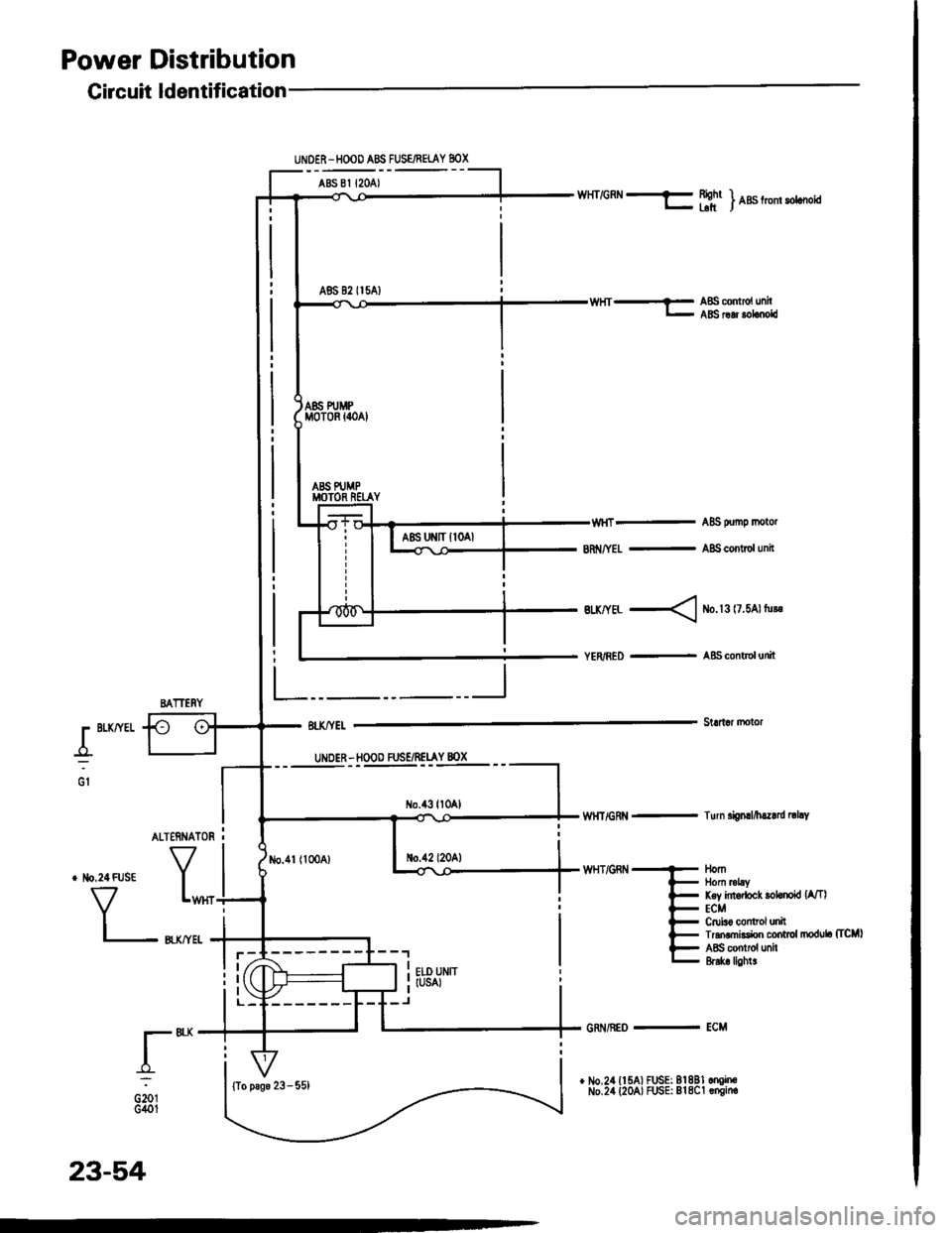
Power Distribution
L"I
.r"-
oiotG401
No.1l (100A)
UNOER-HOOD ABS FUSE/FEIAY 8OX
ABS 81 {2OA)
A86 82 II5AI
Gircuit ldentification
BATTERY
WHT/GRN f Bightr- blt) nas trom sotcooia
ABS oumo motor
8n /YEL - A8S contol unit
Btx/YEL < ib.l3 l7.5Al tu!.
YER/RED - A&S control unit
Stldar motorr BLKffEL
_o_:UNDER - HOOD FUSE/RELAY 8OX
No.43ll0Al
no.42 l20A)
wHT/GRt{ - Turn si0nrl/h.z.rd |thY
WHT/GRN
AL]ERNATOR I
tlomllom mLyKey intodock lohnokl {A/TlECMCruiso control unilTran.mksion control modub (TcMl
ABS contiol unh&6k lighl!
{To psge 23 - 55)
23-54
GRi{/REo - ECM
Page 1163 of 1413
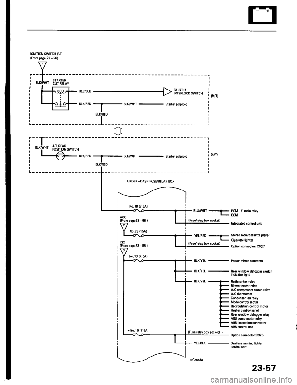
IGNITION SWTCH ISTIlFrom p.!€ 23 - 561
f7
I.---F-------lI-lSTARTFPi Bffi,!'HT 6u?'ili,iY i| -' r r l clurcr It-11iPt ;rui8rr H inl-rhicicxswrcr 1,,,,,,Itill-+{ .'.i o-F BIK/RED --.5 BLX/!\,HT - st.der sotenoid il-l I r
BLK/REO
fr
r---
uxrivn Sr$!gfr*,r.,
L€-eumoBLKMHT - Starlsr solenoki
-------J
UNDER -DASH FUSEiRELAY BOX
No.l817.5A)ELUMHT --?- PGM _ Ft msin rctay- ECM
lnt€gretod control unit
St6r6o radio/c$r€tt6 playot
Cig€rone lightor
Option connoctor: C927
Pow6r minor *tuetols
noar wandow dologgor switchindicrtor light
R6dietor fan robyElowor motor rclayfuC compr$sor clutch rsl6yA/C lhomGtstCond6ns& tan ml6yMod6 control motorRocicubtion control motorH6at€r control panolRear window deloggor relayABS pomp motor tolayABS insp€ction connoctorABS contrcl unit
Option connoctor:C925
Daytime running lightscontrolunit
(From pag623-56 )
No.23ll5AlYEURED --E
lG2lFrom p.!623- 56 ){Fus€/relay box sockotl
+ l,lo,16 {7.5A1
23-57
Page 1167 of 1413
Cor|danlor lan motor
l-
-f,:
G15l
h.ldtgh lLow be.ml
UI{DER - HOOO FUSE/R€TAY 8OX
G40tfro p.g. 23 - 62)
+ Rbht tror pr*ino^um .ign.l lehrs Right tro li,. m|.t rhht
Eto unit IUSAI
Elowor motor rolay
R6!r *indow dsloegrr rcby
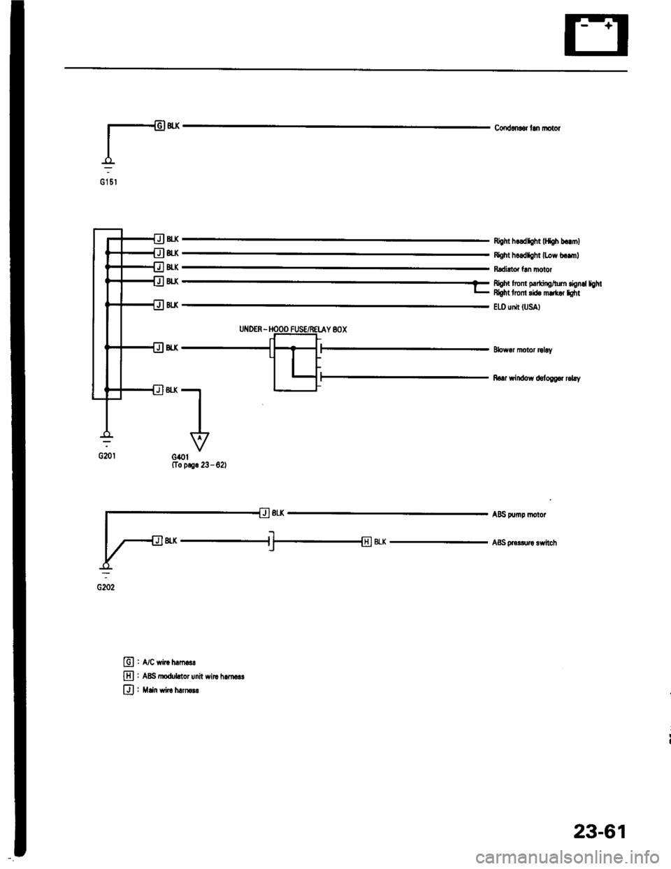
AB{i F np motor
ABS pr..&r! lwltchau#eu
E , A/c *ir" tr".osr
E : ABS dbduknor unit witc hrrn .r
Ul : Min wirr h.moB
23-61
Page 1170 of 1413
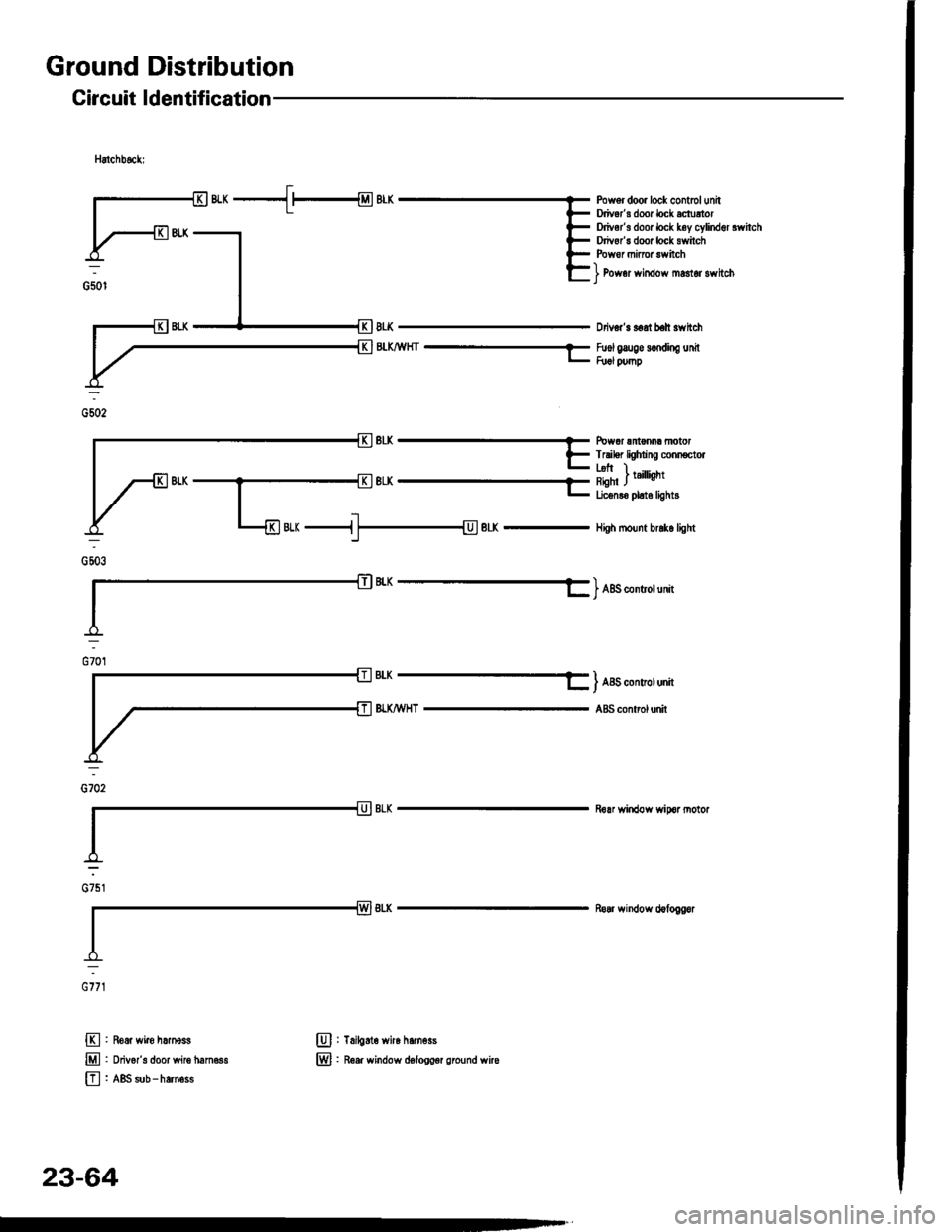
Ground Distribution
Circuit ldentification
Hstchbsckl
8r-K
BLK,lVHT-----
Pow6r door lock contolunhDriver'B door lock ectrrtorDriv6r's door lock k6y cylind6l swhchDrivor's door lock switchPowor mirroa swhch
] Pow6r window manor switch)
Ddver'3 seat bah 3whch
Fuol g&lge s€odiog unilR rl pump
Powor sntonm motorTnibr lighing conn€ctor
E
E
E
Roar wiro harnoss
Ddv6r's doorwileham63s
ABS sub-hernoss
Tailgato wirc hamoss
R6er window d6lo9g€r gro{nd wirc
@:
@:
nuo,
L Lrh I;l:. I taillisht
E Lic€nro ph6 light3
eLx -i]- BLK - Hish rDunt br.k6 tisht
BtK --------- ) ABs *nuor uni
AIY_II_ I ABS contolunh
BI.KA.VHTABS control unh
Rorr wirdow wipcr notor
Ro window d€foggor
cirt
nirt
23-64
Page 1171 of 1413
![HONDA INTEGRA 1994 4.G Service Manual S€d8n:
,.-*-{.4rr-*Powgr door lock contrclunitDrivors door lock actustorD ve/s door lock key cylind€l rwhchDdv6rs door lock switch
] Power window mrster switch)
Drivors soat bolt swhch
Brx,4/vH HONDA INTEGRA 1994 4.G Service Manual S€d8n:
,.-*-{.4rr-*Powgr door lock contrclunitDrivors door lock actustorD ve/s door lock key cylind€l rwhchDdv6rs door lock switch
] Power window mrster switch)
Drivors soat bolt swhch
Brx,4/vH](/img/13/6067/w960_6067-1170.png)
S€d8n:
,.-*-{.4rr-*Powgr door lock contrclunitDrivor's door lock actustorD ve/s door lock key cylind€l rwhchDdv6r's door lock switch
] Power window mrster switch)
Drivor's soat bolt swhch
Brx,4/vHr --E
lfr] ff;nj *",r *n
Irunk latch swhchf l8iler lighting connectorLicoruo pl.to lightsRioht I .L€-ft J nnst rrn gnr
Riohr ) .... .L€-ft J ran||gnr
Power anlonna mototHigh mo0nt bt'k6lightRear window dotoggor
] oo "onuo,unn
t,*----l ,_^
=,-"*- - f ABs contrclunh
@:
@:
E'
Ddvo/s door wir€ hemoss
ABS sub - hafn6s.
G5o2
otoa
.:
G702
23-65
Page 1174 of 1413
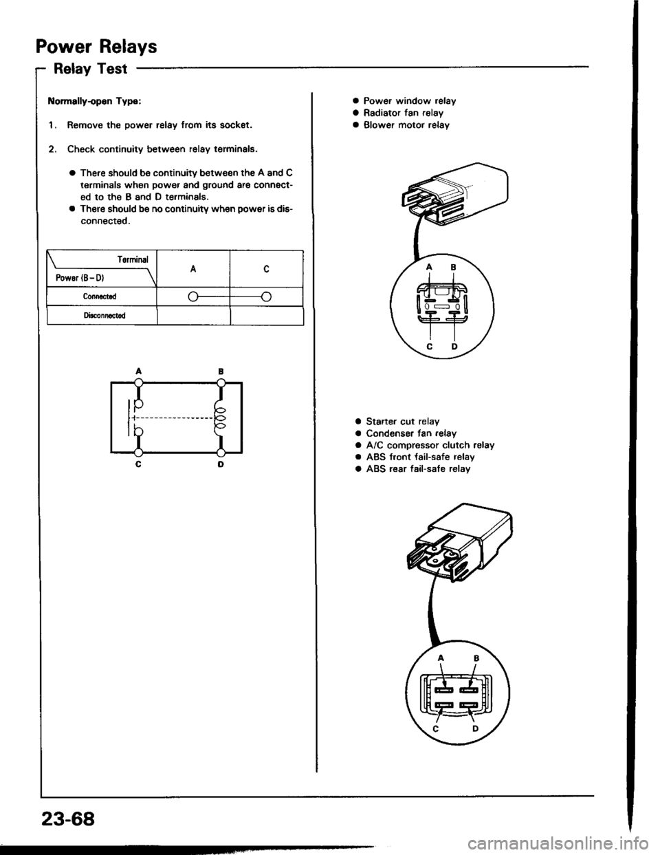
Power Relays
Relay Test
t{ormally-op€n Type:
1. Remove the power relay from its sockat.
2. Check continuity between relay terminals.
a There should be continuity between the A and C
terminals when power and ground ar€ connect-
ed to the B and D t€rminals
a There should be no continuitv wh€n power is dis-
connected.
T6rminal
PowEr (B- D)A
Connactod
Di!c!nnact6d
IP
I
I
tb
23-68
a Power window relay
a Radiator fan relay
a glower motor relav
a Staner cut relay
a Condenser fan .elay
a A/C compressor clutch relay
a ABS t.ont {ail-safe relay
a ABS lear fail-sate relav
.AB
\/
tffit
t[fT4r
\C D,
Page 1205 of 1413
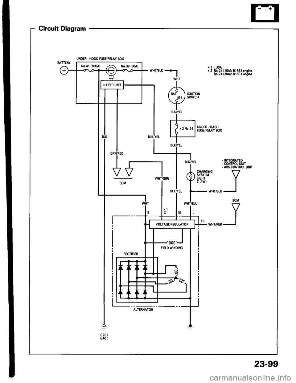
Circuit Diagram
UI,IDER - HOOD FUS€/REI.AY 8OX
*1 :USA+2 llo.24 ll SAl: 81881 .mintlo.24 {2041: 818C | .niin6
. NTEGRATEDCOMTNOL UMT. aBs coilTRor- uNn
VI
I
ECM
V
I
I
UNDER_OASHFUSE/REIAY 8OX
oiotG401
No.4t 11004) /a ilo.39l50Al
Fr€|'l) wNort'lc
AI.TERNATOR
23-99
Page 1206 of 1413
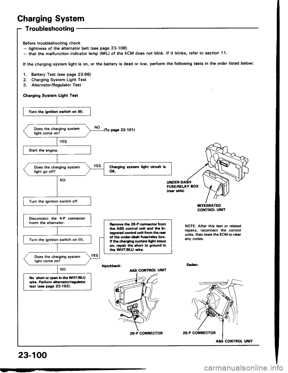
Charging System
Troubleshooting
Bofore troubleshooting check- tightness of the alternator belt (see page 23-1Og).- that the malfunction indicator tamp lMlL) of the ECM does not blink. lf it blinks, refer to section 1 1.
lf the charging system light is on, or th€ battery is dead or low, p€rtorm the following tests in the order listed below:
1. Baftery Test (see page 23-66)
2. Charging System Light Test
3. Alternator/RegulatorTest
ChErging Sysrom Light T6tt
o pago 23-1011
FUSE/RELAY BOX(r..r tid.)
I'{TEGRATEDCO]TTROL UI{IT
NOTE: After this test or relaledrep6irs, roconnoct the controlunits. th6n aoset th€ ECM to cloarany cooos.
H.tchb.ck:Sad.n:
ABS COI{TROL UNIT
2A-P CONi{ECTOR
23-100
Tu]n tho ignhlon srvitch on (lll.
Does th€ charging syslemlight come on7
Does tho charging systemlight go ott?
Turn the ignition switch otf.
Disconnect the 4-P connoctorlromt th€ altornator.Ramova tfto 26-P connactd tromth. ABS control unh snd lh. in-tggrotad conrol unh ttoln tha tadol tho und..dlrh tu!a/r.l.y box.It thr .hlrglng .yrtom lighl .l.Y.on, rrpalr tho ahon to ground Inrhr WHT/BLU wi...
Turn the ignition switch on {ll),
Does the charging systemlight come on?
tlo rhon o. opon h ih. WIfT/BLUwho. Porfom dtomrtor/rogdttolrost beo pag. 23-l02l.
26.P CON ECTOR
ABS CONTROL
Page 1221 of 1413
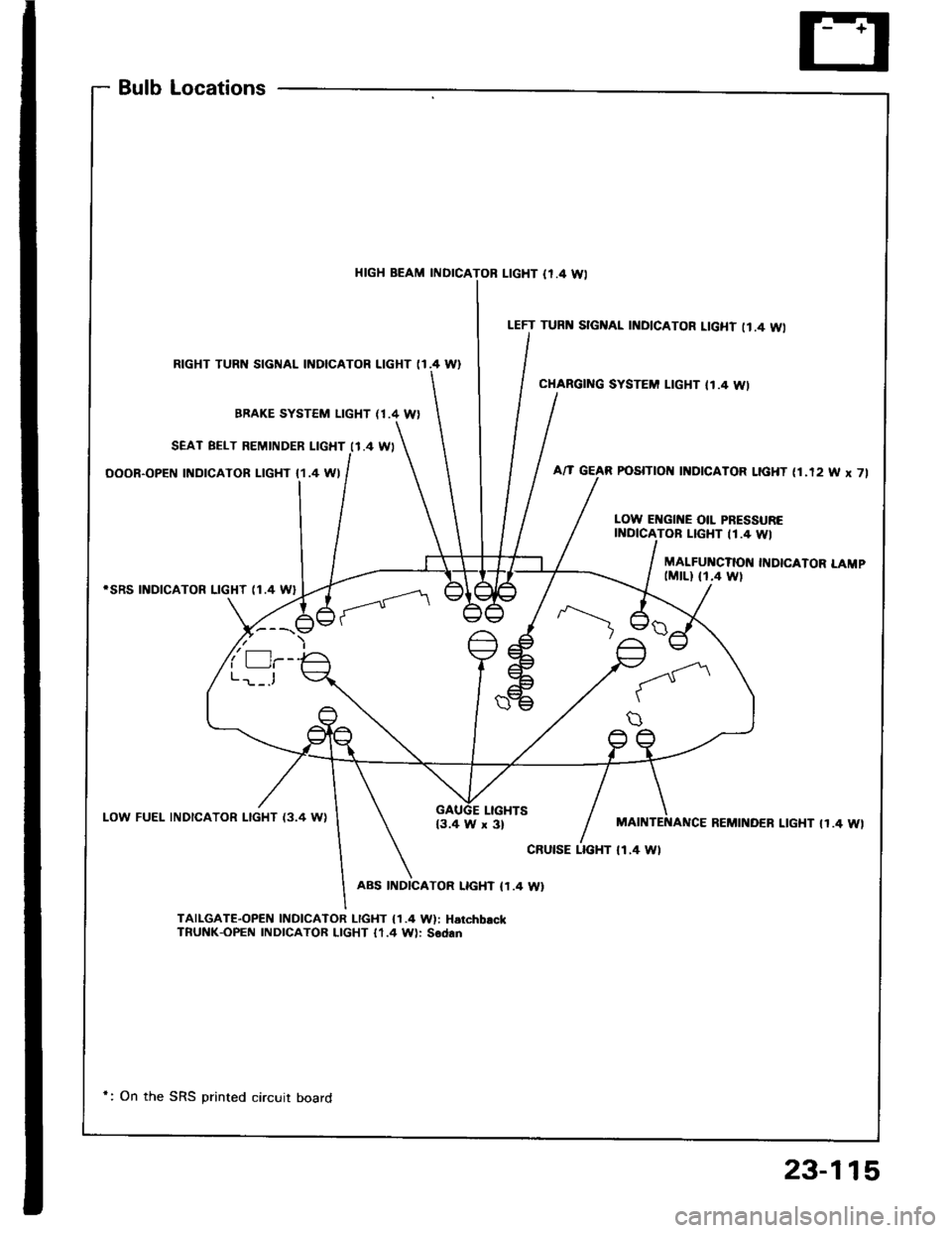
BulbLocations
HIGH BEAM INDICAL|GHT {r.4 Wl
RIGHT TURN SIGNAL INDICATOR LIGHT (I.4 W}
BBAKE SYSTEM LIGHT (1.4 W)
SEAT BELT REMINDER LIGHT I1.4 WI
OOOR-OPEN INDICATOR LIGHT {1.4 WI
iSRS INDICATOR LIGHT (1.4 W}
LOW FUEL INDICATOR LIGHT {3.4 WILIGHTS{3.4 W x 3}
ABS INDICATOR LIGHT (1.4 W}
TAILGAT€-OPEN INDICATOR I-IGHT {1.4 W): HarchbackTnUNK-OPEN INDICATOR LIGHT 11.4 W): Sodan
LEFT TURI{ SIGNAL INDICATOR LIGHT II.4 WI
CHARGING SYSTEM LIGHT II.4 WI
POSITIOII I]{DICATOR LIGHT (1.12 W x 7l
LOW EI{GII{E OIL PRESSURETOB LIGHT 11.4 WI
MALFUI{CTION INDICATOR LAMP(MrLl fi.4 wt
MAINTENANCE REMINOER LIGHT IT.4 WI
cRutsE LTGHT tl.4 Wl
*: On the SRS printed circuit board
23-115