Valve clearance HONDA INTEGRA 1994 4.G Owner's Manual
[x] Cancel search | Manufacturer: HONDA, Model Year: 1994, Model line: INTEGRA, Model: HONDA INTEGRA 1994 4.GPages: 1413, PDF Size: 37.94 MB
Page 666 of 1413

41.
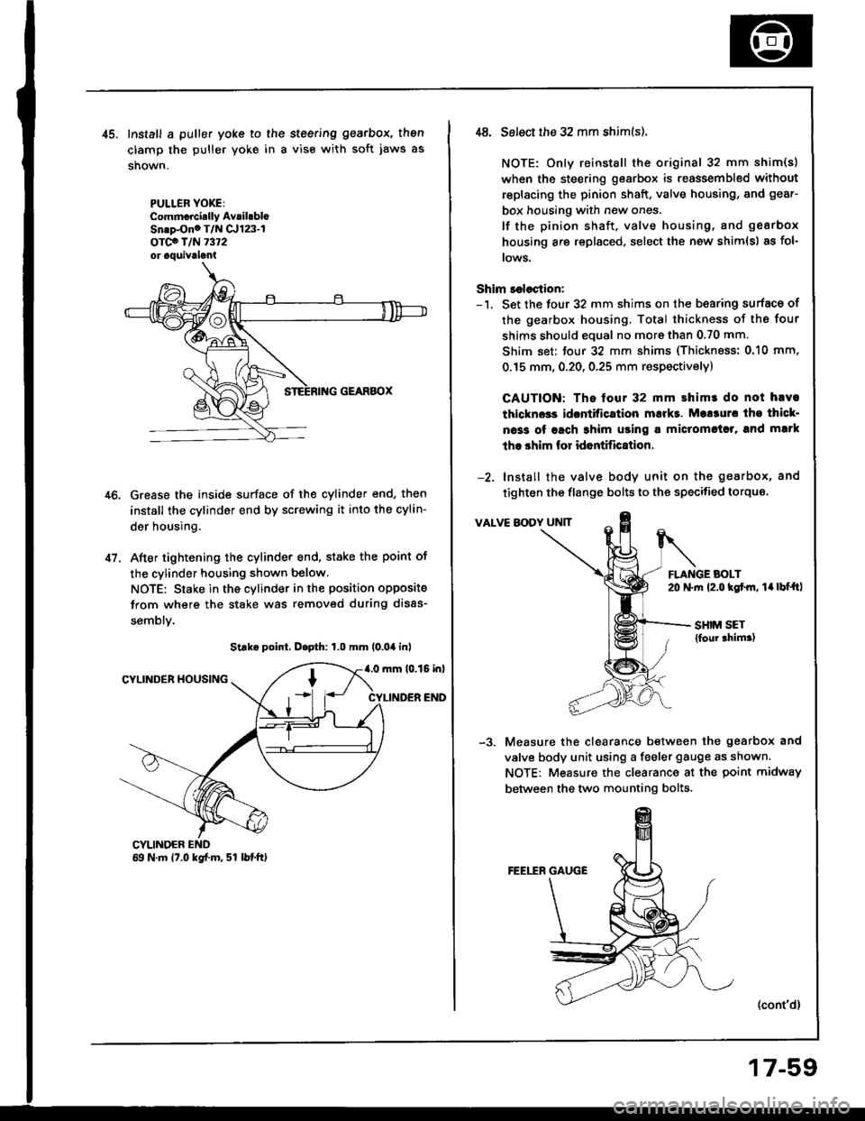
Install a puller yoke to the steering gearbox, then
clamp the puller yoke in a vise with soft jaws as
shown.
PULLER YOXE:Commcrcirlly AvrihbloSn.p-Ono T/N Cr123-lorco T/N 7372or aquivrlani
Grease the inside surface of the cylinder end, then
install the cylinder end by screwing it into the cylin-
der housing.
After tightening the cylinder end, stake the point of
the cylinder housing shown below.
NOTE: Stake in the cylinder in the position opposite
from where the stake was removed during disas-
semblv.
Strke point, D.pth: 1.0 mm (0.04 inl
4.0 mm 10.15 inlCYLINDER HOUSING
CYLINDER END
CYLINOER69 N.m 17.0 kgf.m, 51 lbtft)
,t8. Select the 32 mm shim(s).
NOTE: Only reinstall the original 32 mm shim(s)
when the steering gearbox is reassembled without
replacing the pinion shaft, valve housing, and gear-
box housing with new ones.
lf the pinion shaft, valve housing, and gearbox
housing are replaced, select the new shim{s) as fol-
rows.
Shim r€lection:-'1. Set the four 32 mm shims on the b€aring surface of
the gearbox housing. Total thickness of the four
shims should eoual no more than 0.70 mm.
Shim set: tour 32 mm shims (Thickness: 0.10 mm,
0.15 mm, 0.20, 0.25 mm respectivelyl
CAUTION: The tour 32 mm shimr do not hlva
thlckn$s idcntitication mukt. Mo!3ur. tho thicl-
oa33 of rach 3him using a miclomctrl, and mlrk
tho shim lor id6ntific8tion.
-2. Install the valve body unit on the gearbox, and
tighten the flange bolts to the specitied torque
VALVE BODY UNIT
FLANGE BOLT20 N.m {2.o kgtm, 14lbt'ftl
SHIM SET{foul thim.)
Measure the clearance between the gearbox and
valve body unit using a feeler gauge as shown.
NOTE: Measure the clearance at the point midway
between the two mounting bolts.
(cont'd)
17-59
Page 667 of 1413

Steering Gearbox
Reassembly lcont'd)
-4. Determine the requifed thickness of the 32 mm
shims by subtracting the clearance obtained in thestep -3 from the total thickness of the four shims.(Total thickness of the 4 shims) - (Clearance) =
Required thickness of the shims
NOTE: Select the shims so that th6 total thicknessis close to, but less than the required thickness.
Exampls:
Measu.ement is 0.28 mm (0.011 in):
0.70 - 0.28 = 0.42 mm (0.028 - 0.011 = 0.0't7 in)
The selected shims should be 0.25 mm (O.O1O in) and0.15 mm (0.005 in) in thickness.
lf the required shim thickness is 0.lO mm or less, no
shims are necessary.
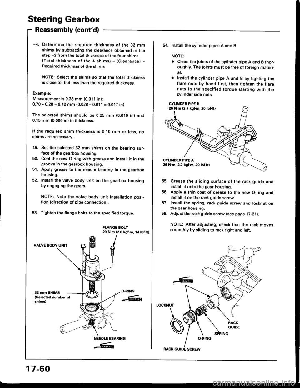
i[9. Set the selected 32 mm shims on the bearing sur-face of the g€arbox housing.
50, Coat the new O-ring with gresse and install it in thegroove in the gearbox housing.
Apply grease to the needle bearing in the gearbox
housing.
Install the valve body unit on the gearbox housing
by engaging the gears.
NOTE: Note the valve body unit installation posi-
tion (direction of pipe connection).
Tighten the flange bolts to the specified torque.
FLANGE BOLT20 N.m (2.0 kgt m, 14lbf.ft)
VALVE BODY UNIT
ct.
O-RING
-ffiti
NEEOLE BEARING
_#{
17-60
BACK GUIDE SCREW
54. Installthe cylind6r pipes A and B.
NOTE:
. Clean the joints ofthe cylinder pipe A and B tho.-oughly. The joints must be free of foreign mat€.i-
at,
o Install the cylinder pipe A and B by tighting theflare nuts by hand first, then tighten the flarenuts to the specified torque starting with thecylinder side nuts.
CYLINDER PIPE B
Grease the sliding surface of the rack guide andinstall it onto the gear housing.
Apply a thin coat of grease to the n€w O-ring andinstall it on the rack guide screw.
Install the spring, rack guide screw and locknut onthe gear housing.
Adjust the rack guide screw (see page l7-21).
NOTE: After adjusting, check that the rack movessmoothly by sliding to rack right and left.
LOCKNUT
-6t
26 N.m (2.7 kg{.m,20lbtft)