door lock HONDA INTEGRA 1994 4.G Workshop Manual
[x] Cancel search | Manufacturer: HONDA, Model Year: 1994, Model line: INTEGRA, Model: HONDA INTEGRA 1994 4.GPages: 1413, PDF Size: 37.94 MB
Page 34 of 1413
![HONDA INTEGRA 1994 4.G Workshop Manual Design Specifications
]TEMMETRICENGLISHNOIES
: vENSTONSOveralllength 3 DOOR
4 DOOR
Ov€rallWidth
Overall Height 3 DOOR
4 DOOR
Wheelbase 3 DOOR
4 DOOR
Track F/R
Ground Clearance
Seating Capacity
4.38 HONDA INTEGRA 1994 4.G Workshop Manual Design Specifications
]TEMMETRICENGLISHNOIES
: vENSTONSOveralllength 3 DOOR
4 DOOR
Ov€rallWidth
Overall Height 3 DOOR
4 DOOR
Wheelbase 3 DOOR
4 DOOR
Track F/R
Ground Clearance
Seating Capacity
4.38](/img/13/6067/w960_6067-33.png)
Design Specifications
]TEMMETRICENGLISHNOIES
:' vENSTONSOveralllength 3 DOOR
4 DOOR
Ov€rallWidth
Overall Height 3 DOOR
4 DOOR
Wheelbase 3 DOOR
4 DOOR
Track F/R
Ground Clearance
Seating Capacity
4.380 mm
4.525 mm
'1,710 mm
1,335 mm
1,370 mm
2,570 mm
2,620 mm
't,475/1,470 mm
150 mm
Four (3 DOOR)
172.1in
178.1 in
67.3 in
52.6 in
101.2 in
103.1 in
5|8.1/57.9 in
Five (4 DOOR)
,rerght (usA)cross V€hicle Weight Rating {GVWR)3,680lbs
'le,ght {CANADA)Gross Vehicls Weight Rating {GVWR)1,670 kg
:\GINEType81881 engine
818C1 engine
Cylinder Arrangement
Bore and Stroke
Displacement
Compression Ratio
81881
818C1
81881
B18C I
81881
B 18C1
81881
818C1
engrne
engane
engrne
engine
engine
engine
engine
engine
L!brication Systom
OilPump Displacement
Wster Pump Displacement
FuelRequired
81881
B18C 1
81881
B 18C1
91881
engrne
engrne
engine
engine
engine
818C1 engine
Water-cooled, 4-stroke DOHC
gasoline engine
Watercooled, 4-stroke DOHC
VTEC gasoline engine
Inline 4-cylinder, transverse
81.0 x 89.0 mm
81.0 x 87.2 mm
1,834 cm3 (mf )
1,797 cm3 (m{)
3.19 x 3.50 in
3.19 x 3.43 in
112 cu-in
110 cu-in
9.2:1
10.0 : 1
Eelt driven, OOHC 4 valve per cylinder
Belt driven, DOHC VTEC
4 valve per cylinder
Forced and wet sump, trochoid pump
50, {53 US qt, 44 lmp qt)/minute'l
71 f {75 US qt, 62 lmp qt)/minute"
140 f (148 US qt, 123 lmp qt)/minute*!
140 f (148 US qt. 123 lmp qt)/minute*'
UNLEADED gasoline with 86 Pump
Octane Numb€r or higher
Premium UNLEADED gasoline wilh
91 Pump Octane Number or higher
STARTERTypo
NormalOutput
NominalVoltage
Hour Rating
Direction of Rotation
Weight
Gear reduction
1.4 kW
12V
30 seconds
Clockwise as viewed lrom g6ar end
3.7 k9 | 8.3lbs
CLUTCHClutch Type
Clutch Facing Area
M/TSingle plate dry, diaphragm spring
Torq!e converter
203 cm'� I 31 sq-in
TRANSMISSIONTransmission Type M/T
Primary Reduction
Synchronized 5-speed forward, 1 reverse
Electronically controlled
4-speed automatic. 1 rcverse
Diract 1 : 1
'1: At 6,000 engine
'2: At 7,600 engine
rpm
rpm
(cont'd)
3-17
Page 40 of 1413
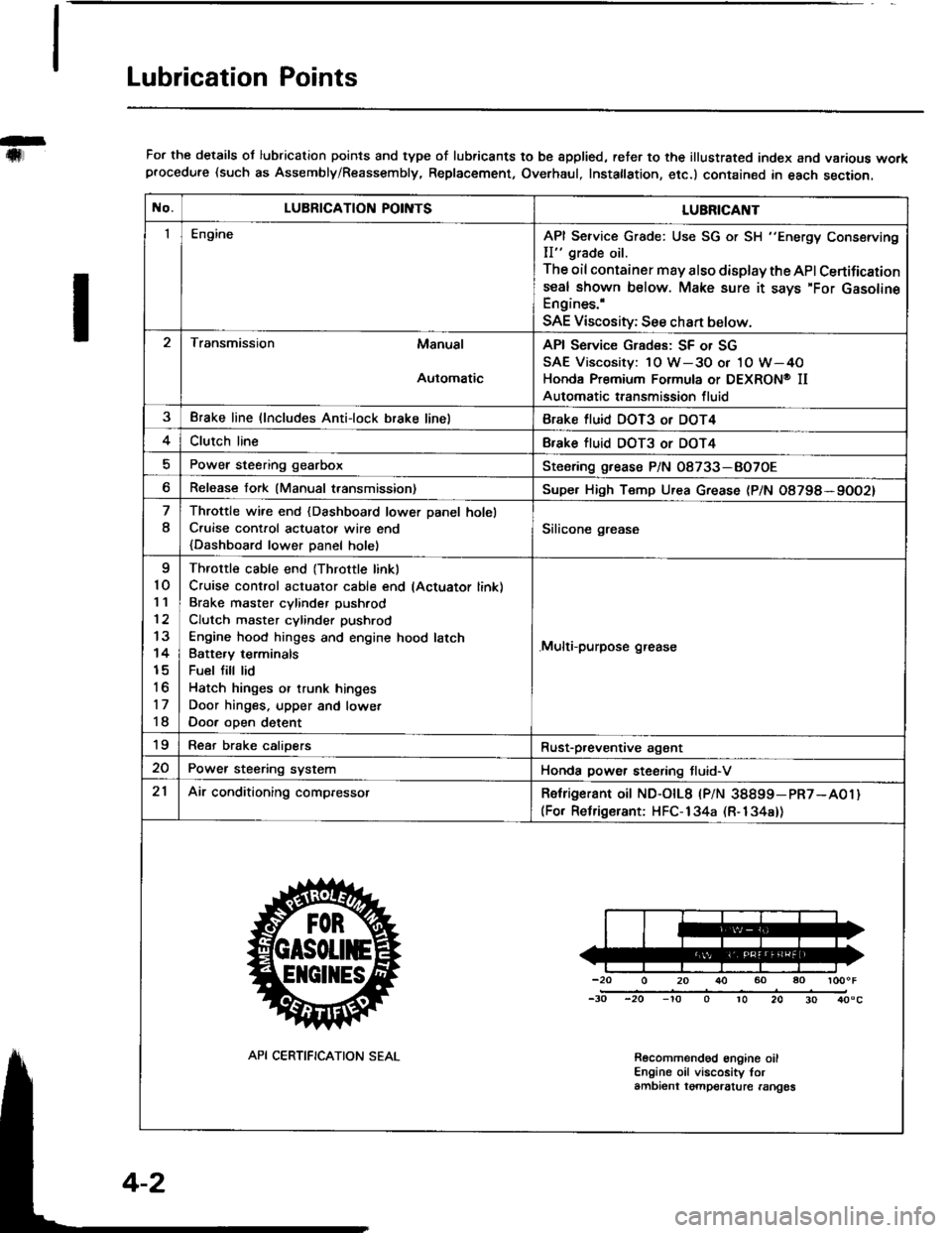
Lubrication Points
For the details ol lubrication points and type of lubricants to be spplied, reter to the illustrated index and various workprocedure (such as Assembly/Reassembly, Replacement, Overhaul, Instatlation, etc.) contained in each section.
No.LUBRICATION POII\ITSLUBRICAI\IT
IEngineAPI Service Grade: Use SG or SH "Energy Conserving
II" grade oil.
The oil container may also display the API Certifications€al shown below. Make sure it says'For GasolineEngines.'
SAE Viscosity; See chan below.
Transmission Manual
Automatic
API Service Grades: SF or SG
SAE Viscosity: 1O W-3O or 1O W-4O
Honda Premium Formula or DEXRON@ II
Automatic transmission fluid
3Brake line (lncludes Anti-lock brake linelBrake fluid DOT3 or DOT4
4Clutch lineBfake tluid DOT3 or DOT4
Power steering gearboxSteoring grease P/N 08733-BO7OE
Release fork (Manual transmission)Supe. High Temp Urea Grease (P/N O8798*9OO2)
8
Throttle wire end {Dashboard lower Danel holel
C.uise cont.ol actuatot wire end
{Dashboard lower Danel holel
Silicone grease
I
10'I '�l
12
13
14
15
to
17
18
Throttle cable end (Throttle linkl
Cruise control actuator cable end lActuator link)
Brake master cvlinder Dushrod
Clutch master cylinder pushrod
Engine hood hinges and engine hood latch
Batte.v terminals
Fuel fill lid
Hatch hinges or trunk hinges
Door hinges. upper and lowet
Door oDen detent
.Multi-purpose grease
19Rear brake calioersRust-p,eventive agant
20Power steering systemHonda power steering tluid-V
21Air conditioning compressorRetrigerant oit ND-otL8 |PlN 38899-pR7-A01)(For Relrigerant: HFC-134a (R-134a))
-20 0 20 r}() 60 ao loooF
-30 -20 -'to o 10 20 30 40"c
Recolnmendod engine oilEngine oil viscosity torambient tgmpelalure rangos
API CERTIFICATION SEAL
Page 914 of 1413
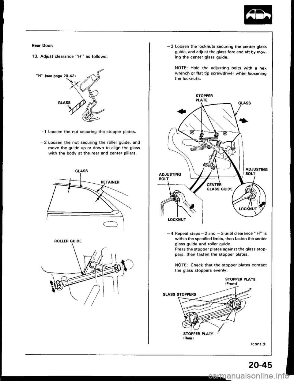
R6ar Door:
'13. Adjust clearance "H" as follows.
"H" lsos page 20-421
- 1 Loosen the nut securing the stopper plates.
2 Loosen the nut securing the roller guide, and
move the guide up or down to align the glass
with the body at the rear and center pillars.
GLASS
ROLLER GUIDE
-3 Loosen the locknuts securing the center glass
guide, and adjust the glass fore and aft by mov-
ing the center glass guide.
NOTE: Hold the adjusting bolts with a hex
wrench or tlat tip screwdriver when loosening
the locknuts.
I
-4 Repeat steps-2 and -3 until clearance "H" is
within the specified limits. then fasten the center
glass guide and roller guide.
Press the stopper plates against the glass stop-
pers, then fasten the stopper plates.
NOTE: Check that the stopper plates contact
the glass stoppers evenly.
STOPPER PLAYElF ontl
204s
Page 915 of 1413
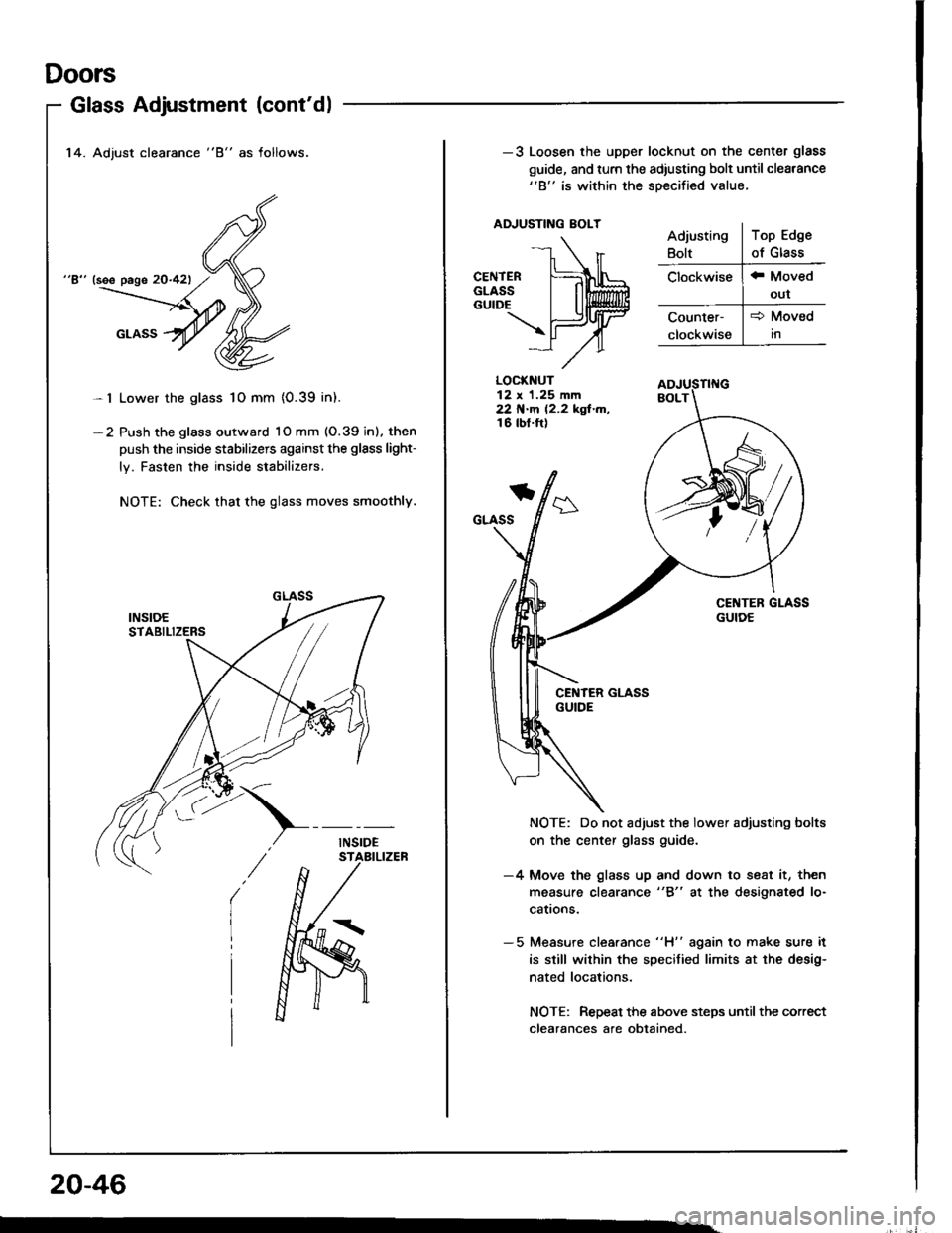
Doors
14. Adjust clearance "8" as follows.
"8" (see page 20-421
Lower the glass 1O mm {0.39 in).
Push the glass outward 1O mm (O.39 inl. then
push the inside stabilizers against the glsss light-
ly. Fasten the inside stabilizers.
NOTE: Check that the glass moves smoothly.
Glass Adjustment (cont'dl
-l
-2
20-46
-3 Loosen the upper locknut on the center glass
guide, and turn the adiusting bolt until cleatance"B" is within the soecified value.
ADJUSTING EOLT
LOCKNUT12 x 1.25 mm22 N.m 12.2 kgf.m,16 tbt.ft)
*
GLASS
NOTE: Do not adjust the lower adjusting bolts
on the center glass guide.
-4 Move the glass up and down to seat it, then
measure clearance "8" at the designated lo-
cattons.
- 5 Measure clea.ance "H" again to make sure it
is still wilhin the specified limits at the desig-
nated locations.
NOTE: Repeat the above steps until the correct
clearances afe obtained.
Page 963 of 1413
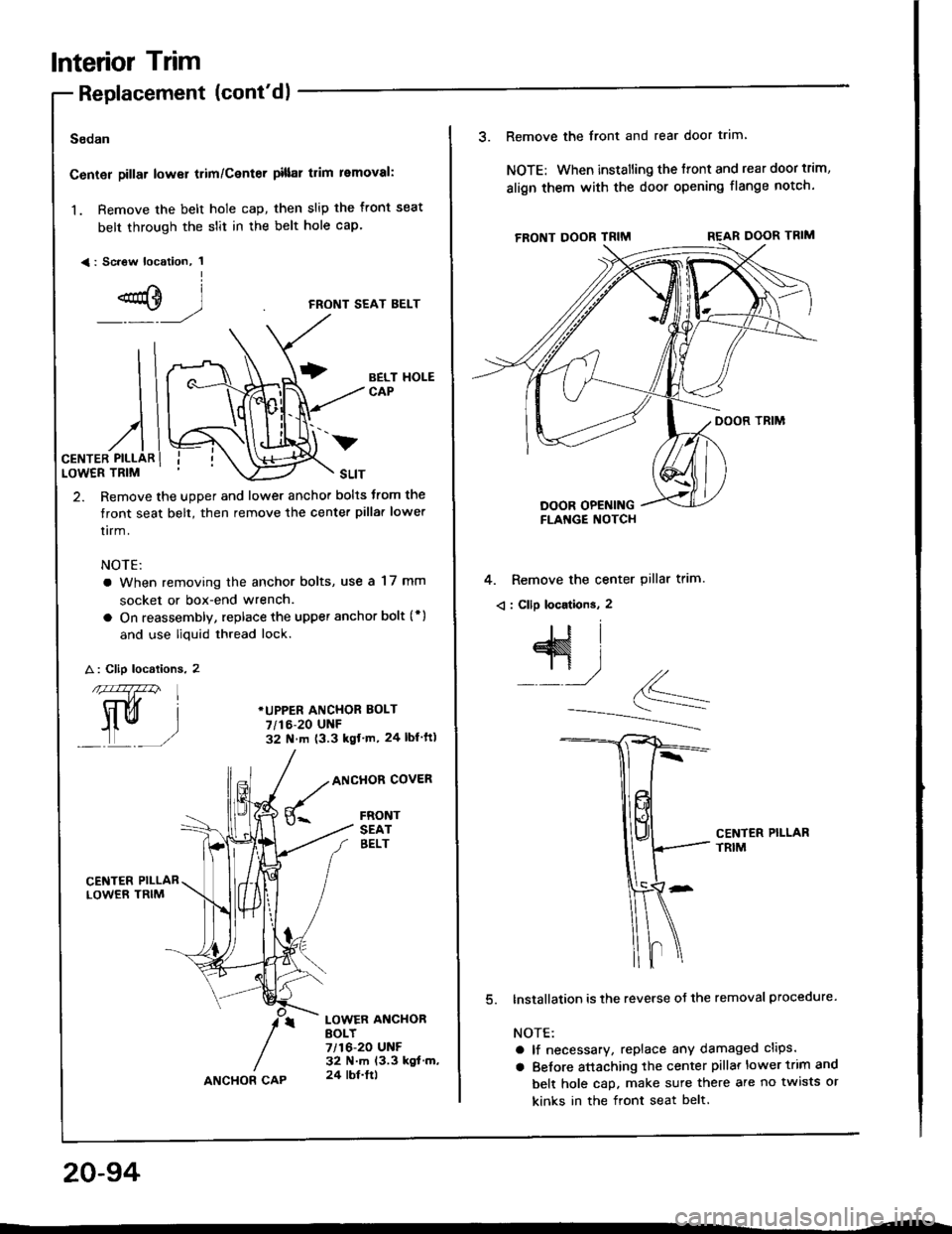
lnterior Trim
Replacement lcont'dl
Sodan
Center pillar lower trim/Center pillal trim removal:
1. Remove the belt hole cap, then slip the front seat
belt through the slit in the belt hole cap.
<: Sc.ew location, 1I
e)
)
2. Remove the upper and lower anchor bolts trom the
tront seat belt, then remove the center pilla. lower
tirm.
NOTE:
a When removing the anchor bolts, use a 17 mm
socket or box-end wrench.
a On reassembly, replace the upper anchor bolt (* )
and use liquid thread lock.
CENTER PILLARLOWER TRIM
FRONT SEAT BELT
BELT HOLECAP
*UPPER ANCHOR EOLT
7/t6-20 UNF32 N m (3.3 kgf'm, 24 lbl ft)
A : Clip localions. 2
nfa147zzn
trui
L_,)
ANCHOR COVER
FRONTSEATEELT
CENTER PILLARLOWER TRIM
LOWER ANCHORBOLY7/16-20 UNF32 N.m 13.3 kgt.m,24 lbt.ltlANCHOR CAP
20-94
v
3. Remove the front and rear door trim
NOTE: When installing the ffont and rear door trim,
align them with the door opening flange notch.
4. Remove the center pillar trim.
< : Cllp locations. 2
CENTER PILLARTRIM
lnstallation is the reverse oJ the removal procedure.
NOTE:
a lf necessary, replace any damaged clips.
a Belore attaching the center pillar lower trim and
belt hole cap. make sure there are no twists or
kinks in the front seat belt.
Page 964 of 1413
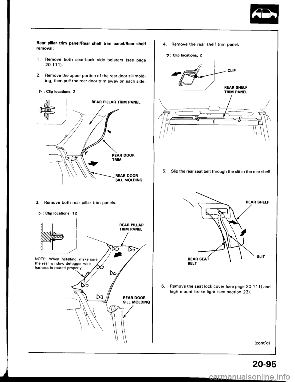
Roar pillar tlim panel/Rear shell trim panel/Rsar she removal:
1. Remove both seat-back side bolsters {see page
20-1 1 1).
2. Remove the upper portion of the rear door sill mold-ing, then pull the rear door trim awav on each side.
REAR PILLAR TRIM PANEL
3. Remove both rear pillar trim panels.
> i Clip localionr, 12
W.,
NOTE: When installing, make sure
REAR PILLARTRIM PANEL
the rear window defogger wireharness is .outed properly.
> : Clip locations, 2
4. Bemove the rear shelf trim panel.
V : Clip locrtions, 2
frl
^affi-_--.]-"t't
Y,r\-J/ '/ - REAR sHEr-F- TRIM PANEL
5. Slip the rear seat belr through the slit in the rear shelf.
REAR SHELF
6.Remove the seat lock cover {see page 20 11 1)and
high mount brake lighr (see section 23).
(cont'd)
20-95
Page 967 of 1413
Headliner
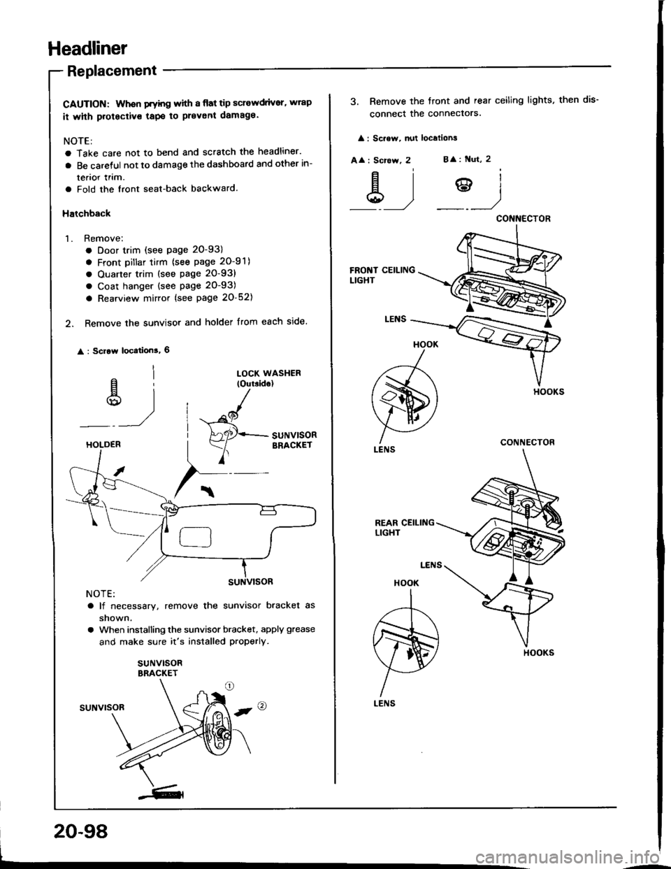
Replacement
CAUTION: Whon Fyhg with I flat tip sclewdrivsr, wrap
it whh protectivs tapo to prevent damaga.
NOTE:
a Take care not to bend and scratch the headliner.
a Be caretul not to damage the dashboard and other in-
terior lrim.
a Fold the front seat-back backward.
Halchback
1. Remove;
. Door trim (see page 20-93)
a Front Dillar tirm {see page 20-91)
a Ouarter trim (see page 20-93)
a Coat hanger (see page 20-93)
a Rearview mirror {see page 20-52)
2. Remove the sunvisor and holder from each side.
: Scrow location!, 6
al
u)
LOCK WASHER(Outside)
"^/
HAaqr+- SUNV|SOR
Y
BRACKETHOLDEB
NOTE:
a lf necessary, remove the sunvisor bracket as
shown.
a When installing the sunvisor bracket, apply grease
and make sure it's installed properly.
suNvlsoRBRACKET
suNvrsoR
20-98
3. Remove the tront and rear ceiling lights, then dis-
connect the conneclors.
: Sc.ew, nut localions
A
: Scrcw, 2B
: Nut, 2
&)?)
HOOK
A
ffi)
LENS
HOOK
I
,r--T-\
m)
H
LENS
CONNECTOR
CONNECTOR
HOOKS
Page 969 of 1413
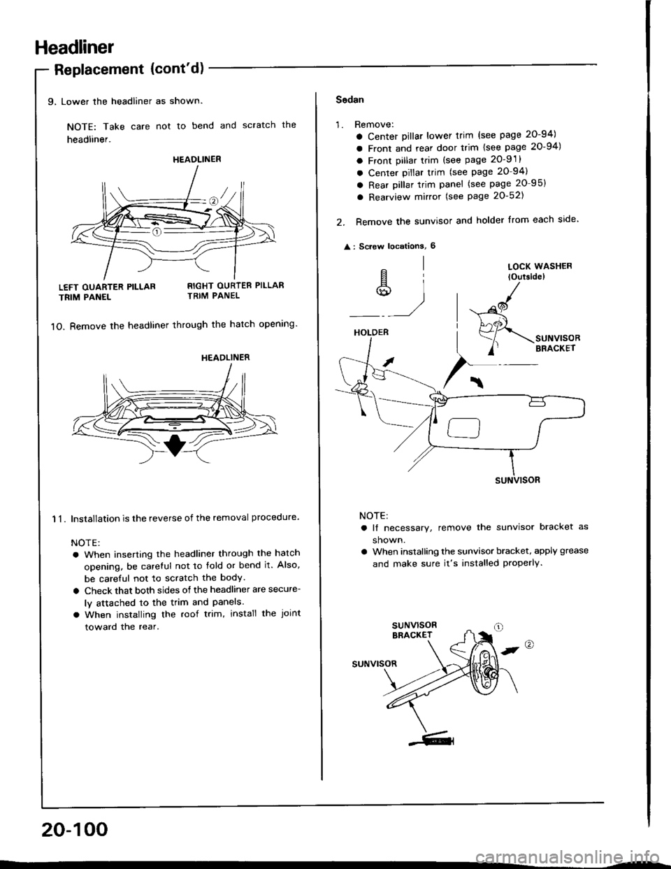
Headliner
9, Lower the headliner as shown.
NOTE: Take care not to bend and scratch the
headliner.
Replacement {cont'd)
LEFT OUARTER PILLAR
TRIM PANEL
11.
RIGHT OURTER PILLARTRIM PANEL
1O. Bemove the headliner through the hatch opening'
Installation is the reverse of the removal procedure.
NOTE:
a When inserting the headliner through the hatch
opening, be careful not to fold or bend it. Also,
be careful not to scratch the bodY.
a Check that both sides of the headliner are secure-
ly attached to the trim and Panels.
a When installing the roof trim, install the Joint
toward the rear.
20-100
HEADLINER
HEADLINER
Sodan
'1.Remove:
a Center Dillar lower trim (see page 20-94)
a Front and rear door trim lsee page 20-94)
a Front pillar trim (see page 2O-9 .
a Center pillar trim (see page 20-94)
a Rear pillar trim panel (see page 20 95)
a Rearview mirror (see Page 20-521
Remove the sunvisor and holder from each side
: Screw locationS, 6
2.
^l
s,1
LOCK WASHER
loutsidel
HOLDER
/
$-.unu,"o"
/' BRACKET
NOTE:
a lf necessary, remove the sunvisor bracket as
shown.
a When installing the sunvisor bracket, apply grease
and make sure it's installed properly.
,@
suNvrsoR
Page 972 of 1413
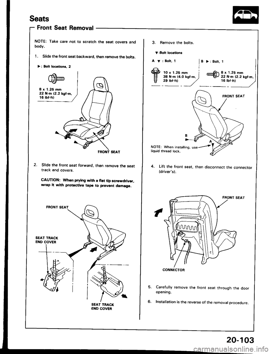
Seats
Front Seat Removal
NOTE: Take care not to scratch the seat covers andbodY.
1 . Slide the lront seat backward, then remove th6 bohs,
Slide the front seat forward, then romove the seattrack end covers.
CAUTlOltl: When prying wlth E flat tip scr.wddvor,w.ap lt whh protactive tapo to prevont damago,
> i Eolt locltlon.. 2
3. Remove the bolts.
V:Boh locatlong
A V : Bolt, 1
I'
> : 8olt,
@8 x '1.25 mm Iii i.:iiil..i'xst.^. I16:t'ftt
- /)
4.
NOTE: When insralling, use--iliquid thread lock.
Lift the front seat, then disconnect the connector(driver's).
Carefully remove the front seat through the dooropening.
Installation is the reverse of the removal procedure.
CONNECTOR
20-103
Page 1062 of 1413
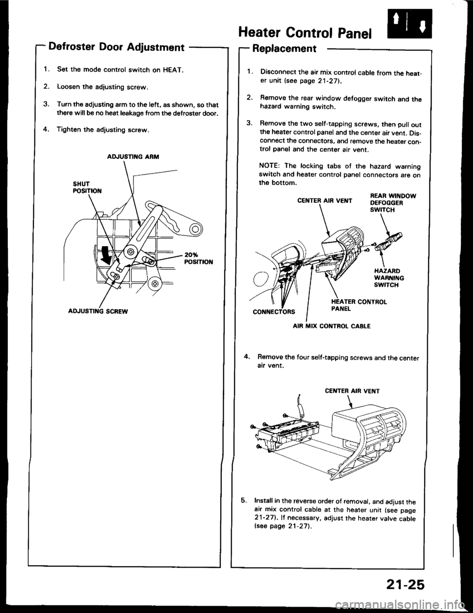
Defroster Door Adjustment
Set the mode control switch on HEAT.
Loosen the adiusting screw.
Turn the adjusting arm to the left, as shown, so that
there will be no heat leakage from the defroster door,
Tighten the sdjusting screw.4.
CE]TTER AIR VEI{T
4. Remove the four self-tapping screws and the centerair v€nt.
Install in the reverse order of removal. and adjust theair mix control cable at the heater unit lsee page21-27). lf necessary, adjust the heater valve cablelsee page 21-27).
REAR WITIDOWDEFOGGERswtTcH
Heater Control Panel
Replacement
Disconned the air mix control cable from the heat-er unit lsee page 21-271.
Remove the rear window defogger switch and thehazard warning switch.
Remove the two self-tapping screws, then pull outthe heater control panel and the center air vent. Dis-connect the connectots, and remove the heater con-trol panel and the center air vent.
NOTE: The locking tabs of the hazard warningswitch and heater control panel connectors are onthe bottom.
AD.'USTII{G ARM
ADJUSTI G SCREW
AIR MIX CONTROL CABLE
CENTEB AIR VE T
21-25