clock HONDA INTEGRA 1994 4.G Owner's Manual
[x] Cancel search | Manufacturer: HONDA, Model Year: 1994, Model line: INTEGRA, Model: HONDA INTEGRA 1994 4.GPages: 1413, PDF Size: 37.94 MB
Page 1006 of 1413
Replacement
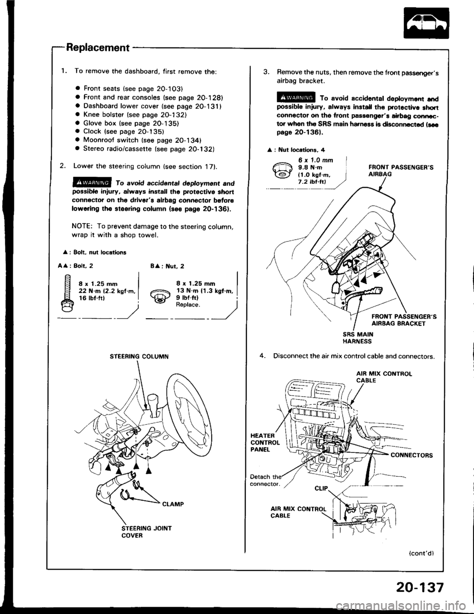
To remove the dashboard, first remove the:
a Front seats (see page 2O-103)
a Front and rear consoles (see page 20-128)a Dashboard lower cover (see page 2O-131)a Knee bolster (see page 2O-132)a Glove box lsee page 2O-135). Clock (see page 20-135)
a Moonroot switch (see page 20-1341a Stereo radio/cassette {see page 20-132)
Lower the steering column (see section 17).
@@ ro avoid accidentat dedoyment andpossiblo in ury, always install the prot€ctive short
connector on tho drivsr's airbag connector bgtor€
lowering tho stooring column (so€ page 20-1361.
NOTE: To prevent damage to the steering column,
wrap it with a shoD towel.
: 8olt, nul locations
A
: Bolt, 28 : ut, 2
8 x 1.25 mm22 N-m 12.2 ksl.m,16 lbt.frl
8 x 1.25 mm
gill$"'l
STEERING COLUMN
3. Remove the nuts, then remove the front passsnger,s
airbag bracket,
@ To avoid accidantar daploym.nr ",'dpossibls iniury, always install th€ protoctiv. 3hqtconnoctor on tho ,ront passongor'a airbag conncc-tor whon tha SRS main ha.na$ is disconncctod llcrpago 20-136).
: Nut locatlons, 4
FRONT PASSENGER'S
FRONT PASSENGER'SAIRBAG BRACKET
4.
SRS MAINHARNESS
Disconnect the air mix controlcable and connectors.
AIR MIX CONTROLCAELE
CONNECTORS
(cont'dl
20-137
Page 1028 of 1413
Hatch Spoiler
Replacement
a Take care not to scratch the hatch.a Open the hatch.
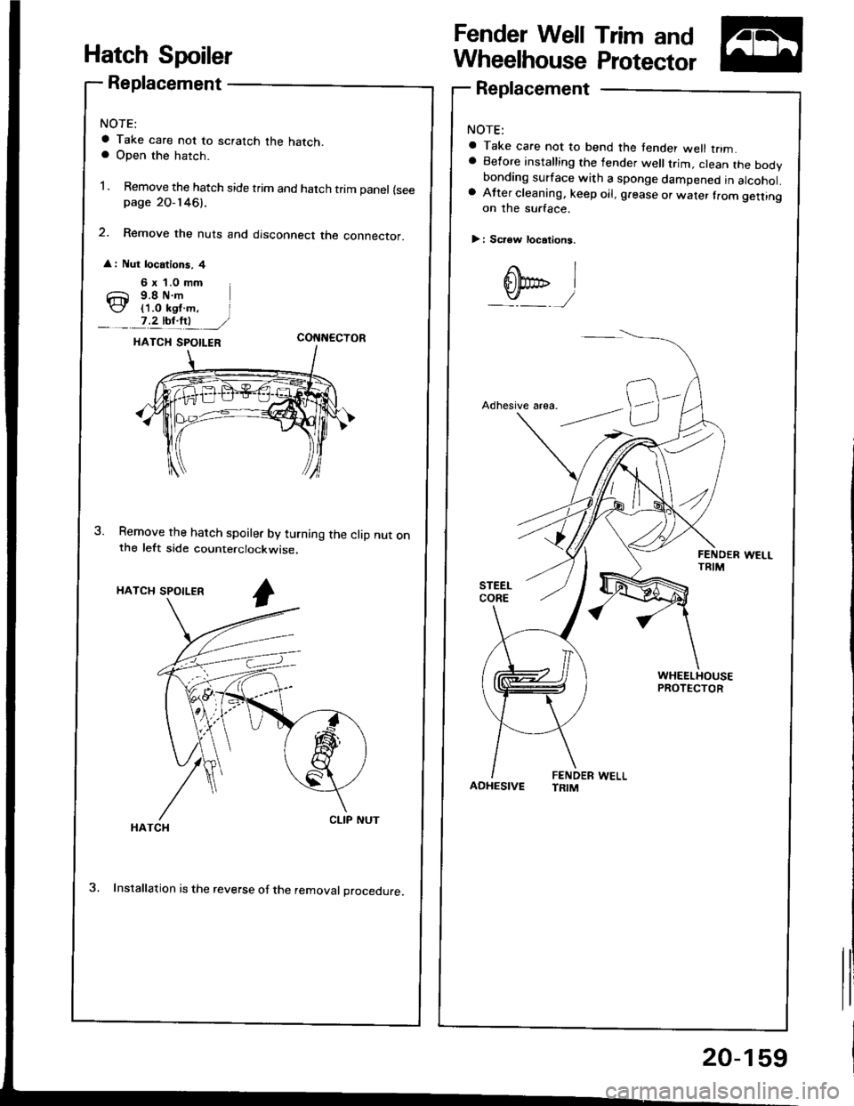
1. Remove the hatch side trim and hatch trim panel (seepage 2O-146).
2. Remove the nuts and disconnect the connector.
: Nut locations, 4
6 x 1.0 mm
Ch 9.8 N.m(J (1.0 ksl m, I__. 7,4b1!t ,/coI{t{EcroR
Remove the hatch spoiler by turning the clip nut onthe left side counterclockwise.
HATCH SPOILER
3. Installation is the reverse of the removal procedure.
Fender Well Trim and
Wheelhouse Protector
Replacement
a Take care not to bend the tender well trim.a Before installing the lender well trim, clean the bodvbonding surface with a sponge dampened in alcohol.a After cleaning, keep oil, g.ease or wafer lrom getlingon the surface.
> i Scr€w locations.
I
ADHESIVEFENDER WELLTRIM
20-159
Page 1138 of 1413
Connector ldentification and Wire Harness Routing
Dashboard wile Ha.n6ss
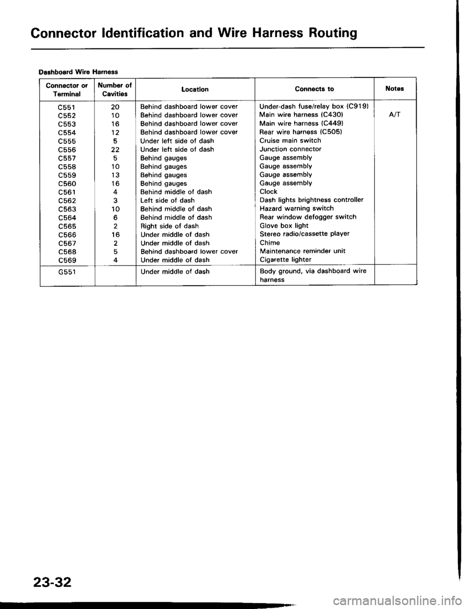
Connector ot
T€rminal
Number of
Caviti6sLocationConnects toNotes
c553
c554
L55b
c556
c557
c558
c560
LCO I
c563
c564
c565
c566
c567
c568a 6ACl
20
10
to
12
5
22
10
13
16
10
6
to
2
Behind dashboard lower cover
Behind dashboard lower cover
Behind dashboard lower cover
Behind dashboard lower cover
Under lett side oJ dash
Under left side of dash
Behind gauges
Behind gauges
Behind gauges
Behind gauges
Behind middle of dash
Left side of dash
Behind middle of dash
Behind middle of dash
Right side of dash
Under middle of dash
Under middle of dash
Behind dashboard lower cover
Under middle of dash
Under-dash fuse/relay box (C919)
Main wire harness (C43Ol
Main wire harness (C4491
Rear wire harness {C505)
Cruise main switch
Junction connector
Gauge assembly
Gauge assembly
Gauge assembly
Gauge assembly
Clock
Dash lights brightness controller
Hazard warning switch
Rear window defogger switch
Glov€ box light
Stereo radio/cassette PlaYer
Chime
Maintenance reminde. unit
Cigarette lighter
Afi
Under middle of dashBody ground, via dashboard wire
harness
23-32
Page 1155 of 1413
Fuse Numb€r AmDs Wire CololGomponent ls) or Circuit (s) Prot8cted
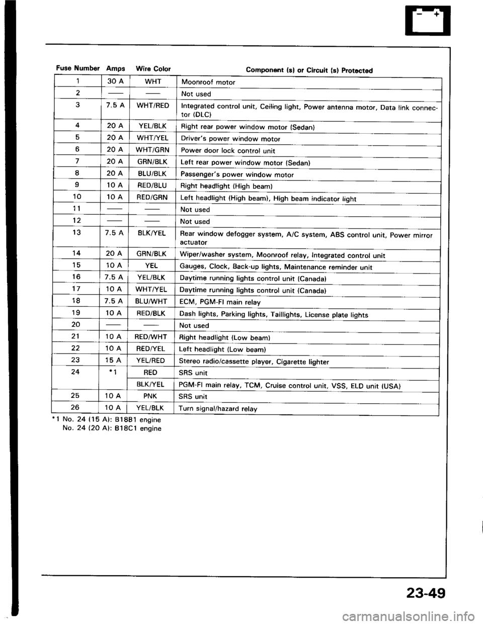
130AWHTMoonroof motor
2Not used
37.5 AWHT/REDIntegrated control unit, Ceiling light, Power antenna motor. Data link connec-tor (DLC)
420AYEL/BLKRight rea. power window motor (Sedan)
520AWHT/YELDriver's power window motor
o20AWHT/GRNPower door lock control unit
720AGRNiBLKLelt rear power window motor (Sedan)
I20ABLU/BLKPassenger's power window motor
I10 ARED/BLURight headlight {High beaml
1010 ARED/GRNLeft headlight (High beam). High beam indicato. tight
11Not used
12Not used
137.5 ABLK/YELRear window defogger system, A/C system, ABS control unit, power mrrroractuator
1420AGRN/BLKWiper/washer system, Moonroof relay, Integrated control unii'1510 AYELGauges, Clock, Back-up lights, Maintenance reminder unit
to7.5 AYEL/BLKDaytime running lights control unit (Canadal
1710 AWHT/YELDaytime running lights control unit (Csnada)
7.5 ABLU^tvHTECM, PGM-FI main relay'to10 ARED/BLKDash lights, Parking lights, Taillights, License plate tights
20Not used
2110 ARED/WHTRight headlight (Low beam)
10 ARED/YELLeft headlight (Low beam)
2315 AYEL/REDStereo radio/cassette player, Cigarette lighter
24REOSRS unit
BLK/YELPGM-FI main relay, TCM, Cruise controt unit, VSS, ELO unit IUSA)
2510 APNKSRS unit
2610 AYEL/BLKTurn signal/hazard relay'1 No.
No.
24 115 Al:
24 t2O At:.
81881 engine
B18Cl engine
23-49
Page 1158 of 1413
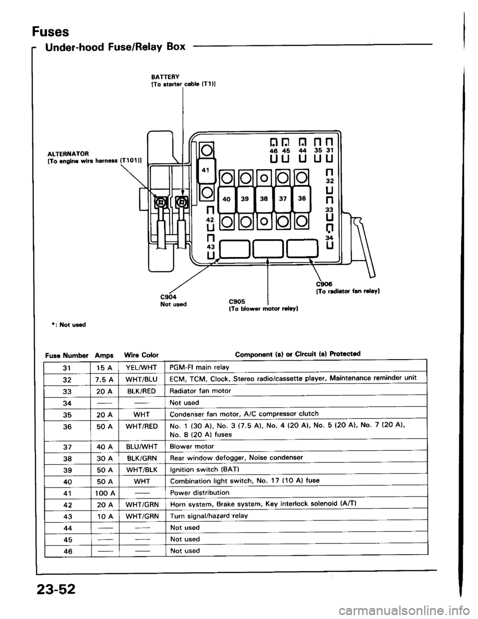
Fuses
Under-hood Fuse/Relay Box
ALTERI{ATOR
fTo .ngino wlto hsrno$ {Tlolll
Not usod
r: l\lot u3.d
umborAmpsColor
nF n nn46 45 /t4 35 3l
UU U UU
n32
U
n
33
U
r:rg
U
n
42
U
n43
U
[To rldidor hn r.l.Yl
Componon! (sl 01 Clrcuit 13) Protoqtod
3115 AYEL/WHTPGM-Fl main relay
327.5 AWHT/BLUECM, TCM. Clock, Stereo radio/cassette plsyer, Maintenance reminder unit
a2204BLK/REDRadiator Jan motor
34Not used
35204WHTCondenser fan motor, A/C compressor clutch
50AWHT/REDNo. I {3O A), No. 3 (7.5 A). No. 4l2O Al, No 5 (2O A), No. 7 (2O A),
No. I (20 A) fuses
3740ABLU/lVHTBlower motor
3830ABLK/GRNRear window defogger, Noise condenser
?q50AWHT/BLKlgnition switch {BAT}
4050AWHTCombination light switch, No. 17 (1O Al fuse
41100 APower distribution
4220AWHT/GRNHorn system, Brake system, Key interlock solenoid (Aff)
4310 AWHT/GRNTurn signal/hazard.elay
44Not used
45Not used
46Not used
23-52
Page 1196 of 1413
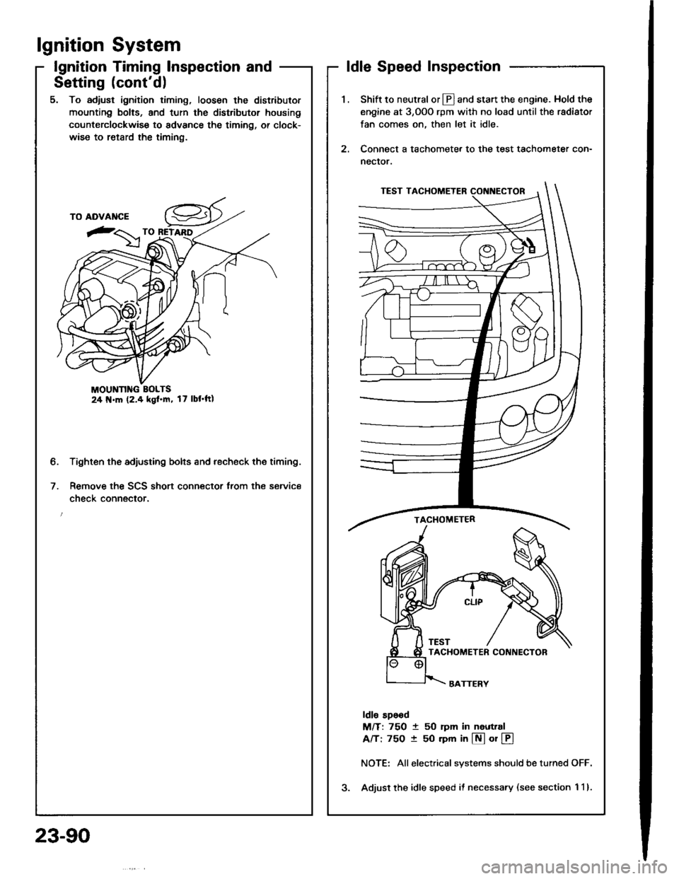
lgnition System
lgnition Timing lnspection and
Setting (cont'd)
5. To adjust ignition timing, loosen the distributor
mounting bolts, and turn the distributor housing
counterclockwise to advance the timing, or clock-
wise to retard the timing.
MOUNN G BOLTS24 N.m (2.4 kgl.m, 17 lbt'ftl
Tighten the adjusting bolts and recheck the timing.
Remove the SCS short connector trom the service
check connector.
2.
ldle Speed Inspection
Shift to neutral or Ll] and start the engine. Hold the
engine at 3,OOO rpm with no load until the radiator
fan comes on, then let it idle.
Connect a tachometer to the test tachometer con-
nector.
ldle sp6od
M/T: 750 t 50 rpm in neuttal
A/T: 75O t 50 rpm in @ or @
NOTE: Allelectrical systems should be turned OFF.
Adjust the idle speed il necessary (see section 1 1).
b.
23-90
Page 1270 of 1413
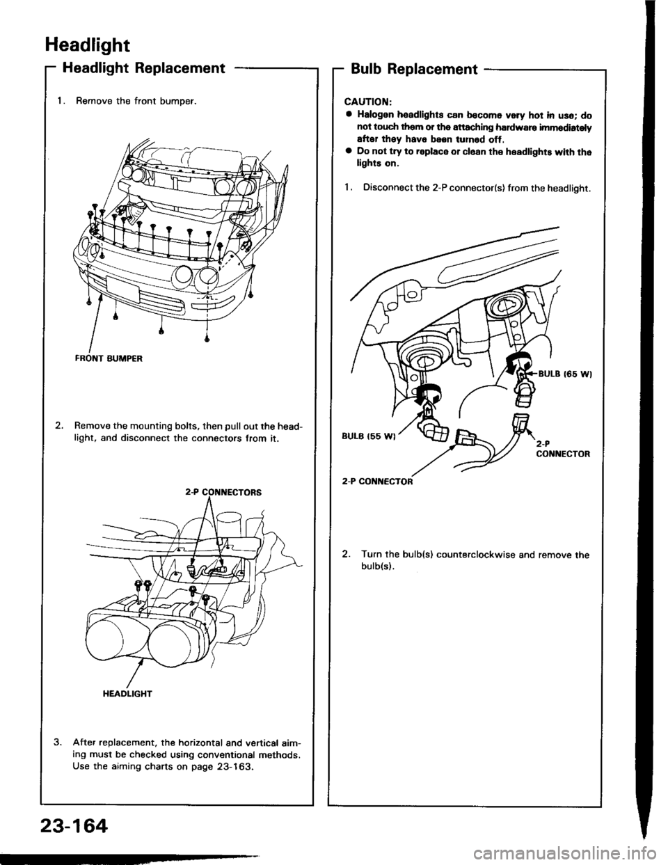
Headlight
Headlight Replacement
1. Remove the front bumoer.
Remove the mounting bolts, then pullout the head-
light, and disconnect the connectors from it.
Afte. replacement. the horizontal and vertical aim-ing must be checked using conventional methods,
Use the aiming charts on page 23-163.
Bulb Replacement
CAUTION:
a Halogon headlights can bocomo voly hot in usa; do
not touc$ them or tho attaching hardware imm6diatoly
arter they hava been lurnod off,a Do not try to roplace or cl6an the headlights with thelights on.
I . Oisconnect the 2-P connector(s) from the headlight.
coNlrtEcToR
2. Turn the bulb(s) counterclockwise and remove the
bulb(s).
FRONT BUMP€R
HEADLIGHT
23-164
Page 1271 of 1413
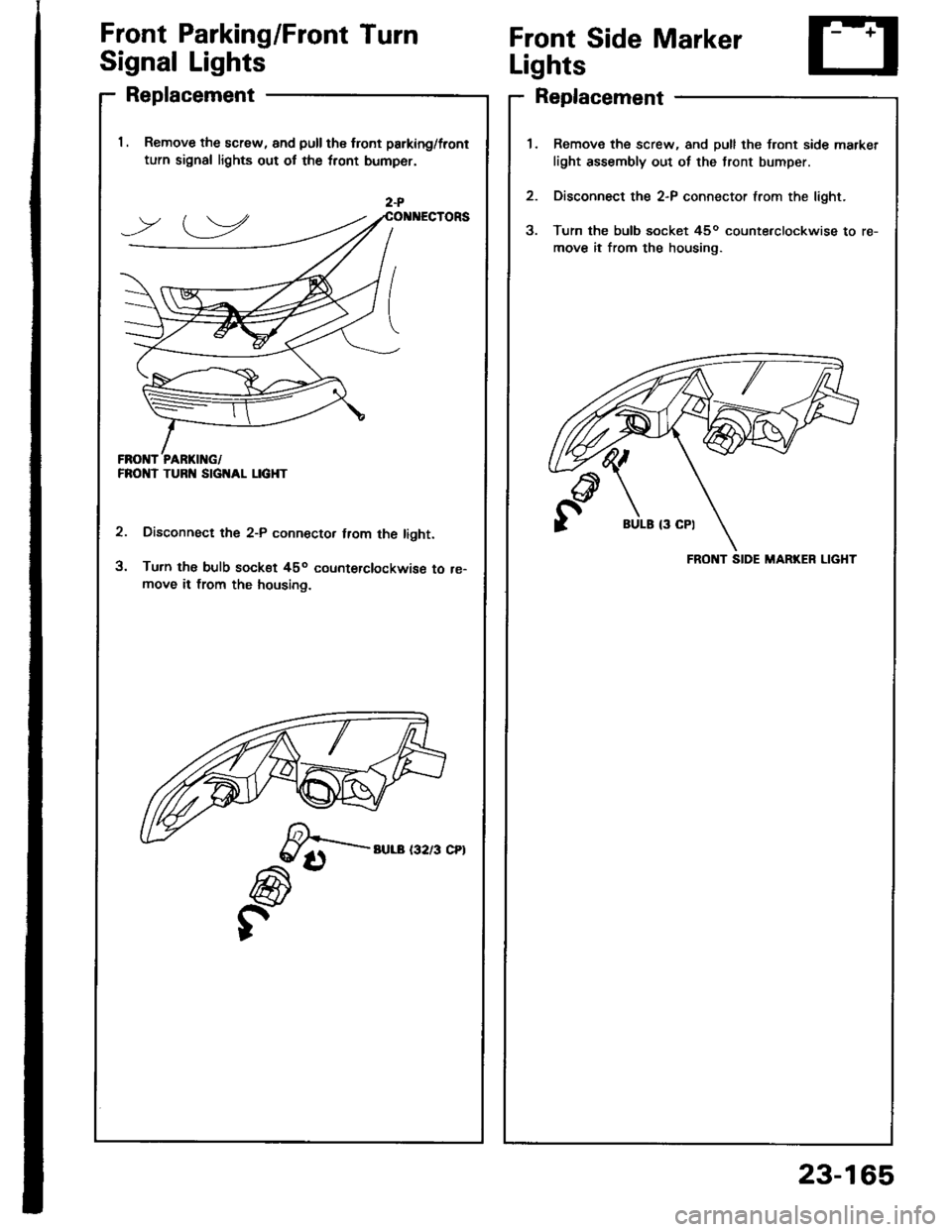
Front Parking/Front TurnFront Side Marker
LightsSignal Lights
Replacement
l. Remove the screw, and pull the front parking/front
turn signal lights out ot the tront bump6r.
Disconnect the 2-P conn€ctor trom the tight.
Turn the bulb sock€t 45o counterclockwise to re-move it from the housing.
Replacement
Remove the screw, and pull the front side marker
light assembly out of the tront bumper.
Disconnect the 2-P connector from the lioht.
Turn the bulb socket 45o counterclockwise to re-
move it from the housing.
BULE {3 CPI
FRONT SIDE MARKER LIGHT
23-165
Page 1275 of 1413
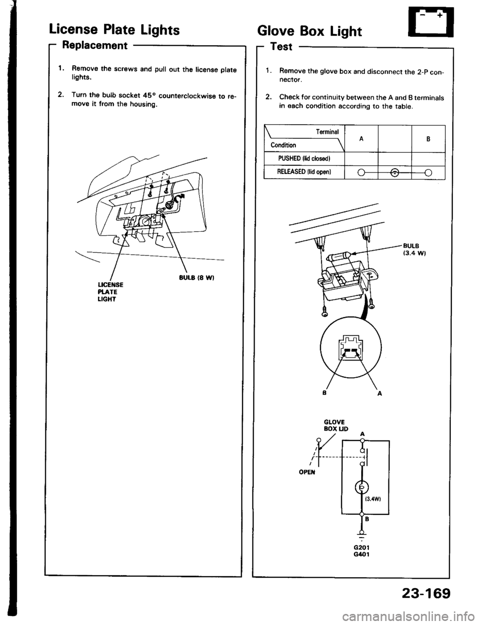
License Plate Lights
Replacement
Remov€ the screws and pull out th6 license platelights.
Turn the bulb socket 45o counterclockwise to re-move it from the housing.
ciorG4{t1
Glove Box Light
Test
Remove the glove box and disconnect the 2-p con-neclor.
Check for continuity between the A and B terminals
in each condition according to the table.
BULB(3.4 W)
Condition
T€rminalB
PUSHED {lid closodl
REI"EASED {lid oDen)o-/:\---o\7
ql-----11
dl
23-169
Page 1289 of 1413
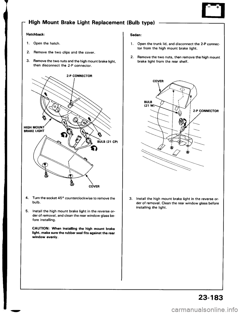
High Mount Brake Light Replacement {Bulb type)
Hatchback:
1. Open the hatch.
2. Remove the two clips and the cover.
3. Remove the two nuts and the high mount brake light,then disconnect the 2-P connector.
Turn the socket 45o counterclockwise to remove thebulb.
Install the high mount brake light in the reverse or-
der of removal, and clean the rear window glass be-
tore installing.
CAUTION: Whon installing ih6 high mount brakelight. make sur6 the rubber soal fits against the realwindow ev6nly.
4.
Sadan:
1. Open the trunk lid, and disconnect the 2-P connec-
tor trom the high mount brake light.
2. Remove the two nuts, then remove ths high mount
brake light from the rear shelt.
2-P CONt{ECTOR
Install the high mount brake light in the reverse or-
der of removal. Clean the rear window glass before
installing rhe light.
2
23-183