5. Check lor 8n op€n in the BLKMHT wire circuit be-
tween the staner and ignition switch, and con-
nectors.
6. Check the ignition switch (see page 23-70).
7, On cars with automatic transmission, check the A/Tgear position switch (neutral position switchl and
connector. On cars with manualtransmission, check
the staner cut relay, clutch interlock switch, and
connectors.
NOTE: Check the No. 39 (5O A) fuse in the under-hood
fuse/relay box for the starter cut relay.
Check tor Woar and Damago:
The starter should crank the engine smoothly and stead-
ily. lf th€ startsr engages, but cranks the engine errati-
cally, remove it. Inspect the starter, drive gear, and
flywheel ring gesr for damage.
a Check the drive gear overunning clutch for binding
or slipping when the armature is rotated with the drivegear held. Replace the gesrs if damaged.
Check Cranking Voltago 8nd Current Draw:
Cranking voltage should be no less than 8.O volts.
Current draw should be no more than 360 amperes.
lf cranking voltag€ is too low, or current draw too high,
check for:
a Fully charged battery
a Open circuit in starter armature commutatot segments
a Starter armature dragging
a Shoned armature winding
a Excessive drag in engine
Chack Cranking rpm:
Engine spsod during cranking should be above 1O0 rpm.
lf spe6d is too low, ch€ck for:
a Loose battsry or starter teminals
a Excessively worn starter brushes
a Open circuit in commutator segments
a Dirty or damaged helical spline or drive gear
a Defective drive gear overrunning clutch
Chock StErtor Disongagomoni:
Press the clutch pedal allth€ way in (M/T), turn the ioni-
tion switch to "lll" and rolease to "11".
The starter drive gear should disengage from the tlywheel
ring gear. When you rolease the key.
lf the drive gear hangs up on th€ flywheel ring gear, check
for:
a Solenoid plunger and switch malfunction
a Dirty drive gear assembly or damaged overrunning
clutch
23-77
lgnition System
Distributor Installation
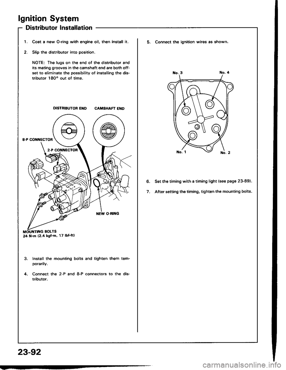
Coat a new O-ring with engine oil, then install it.
Slip the distributor into position.
NOTE: The lugs on the end of the distributor and
its mating grooves in the camshaft end are both off-
set to eliminate the possibility ot installing the dis-
tributor 18Oo out of time.
DISTRIBUTOR END CAMSHAFT END
Install the mounting bolts and tighten them tem-
porarily.
Connect the 2-P and 8-P connectors to the dis-
tributor.
24 N.m (2.4 kgf'm' 17 lbt'ft|
23-92
5. Connect the ignition wires as shown.
Set the timing with a timing light (se€ page 23-89).
After setting the timing, tighten the mounting bolts.

