relay HONDA INTEGRA 1994 4.G Owner's Manual
[x] Cancel search | Manufacturer: HONDA, Model Year: 1994, Model line: INTEGRA, Model: HONDA INTEGRA 1994 4.GPages: 1413, PDF Size: 37.94 MB
Page 272 of 1413
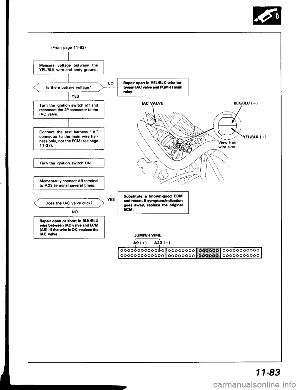
(From page 'l 1-82)
Measure voltago between theYEL/BLK wire and bodv ground.
R.pair op.n In YEL/8LK who b.-twoon IAC vCvc dd PGM-FI mdnrelay.ls th€rs battery voltage?
Turn th€ ignition swirch ott andreconnect thg 2P cohnector to theIAC valve.
Conn€ct the test hs.ness "A"
connector to the main wirs hrr-n6ss only, not the ECM lsee page
t 1-37).
Tu.n tho ignition switch ON.
Momentarily connect Ag torminalto 423 terminol seveaal tim€s.
Sub.titutr ! known{ood ECM.nd ral..t. lt .ymptom/hdlcatioogoa! awsy. rophca tia origlnalECM.
Does th6 IAC valve click?
Raplir op.n or rhort in 8LK/BLUwl]. b.tw.cn IAC v!lv..nd ECM(A91, It th. wlro L OK, r.Dhc.lheIAC v.lv..
IAC VALVEBLK/BLU { _ }
JUMPER WIRE
A9 l+) A23 {-l
1 1-83
Page 286 of 1413
Fuel Supply System
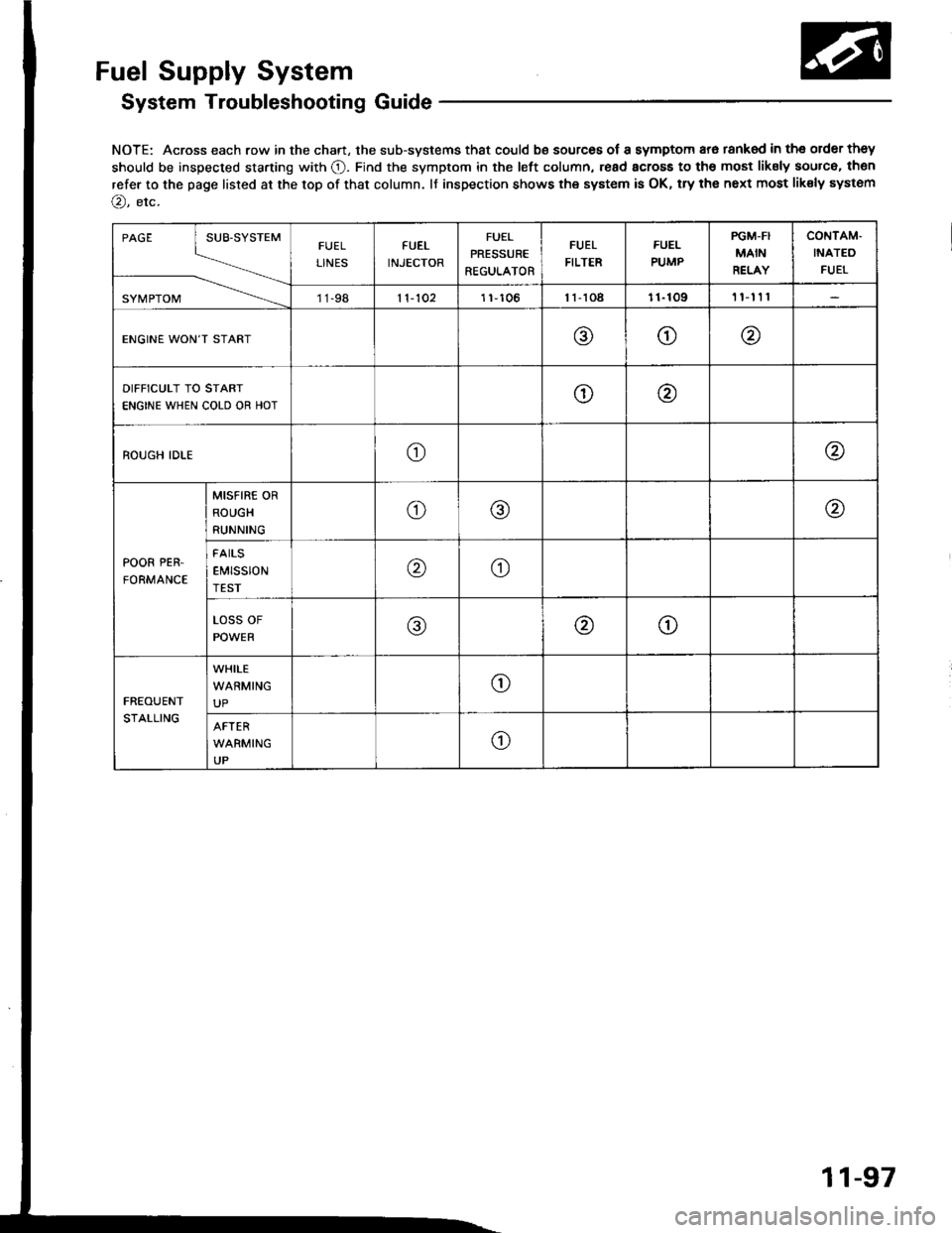
System Troubleshooting Guide
NOTE: Across each row in the chart, the sub-systems that could be sources of a symptom ara tanked in tho order they
should be inspected starting with O. Find the symptom in the left column, read across to the most liksly source, then
refer to the page listed at the top of that column. lf inspection shows the system is OK, try the next most liksly system
@, etc.
PAGE
SYI\4 PTOM
FUEL
LINES
FUEL
INJECTOR
FUEL
PRESSURE
REGULATOR
FUEL
FILTER
FUEL
PUMP
PGM-FI
MAIN
RELAY
CONTAM'
INATEO
FUEI
11-9811-1021 1,106l1-toa11-109t'l'nl
ENGINE WON'T START@o@
DIFFICULT TO START
ENGINE WHEN COLD OR HOTo\4
ROUGH IDLEo@
POOR PER.
FORMANCE
MISFIRE OR
ROUGH
RUNNINGo@@
FAILS
EMtSSION@o
LOSS OF
POWER@@o
FREOUENT
STALLING
WHILE
WARMING
UPo
AFTER
WARMING
UPo
11-97
Page 289 of 1413
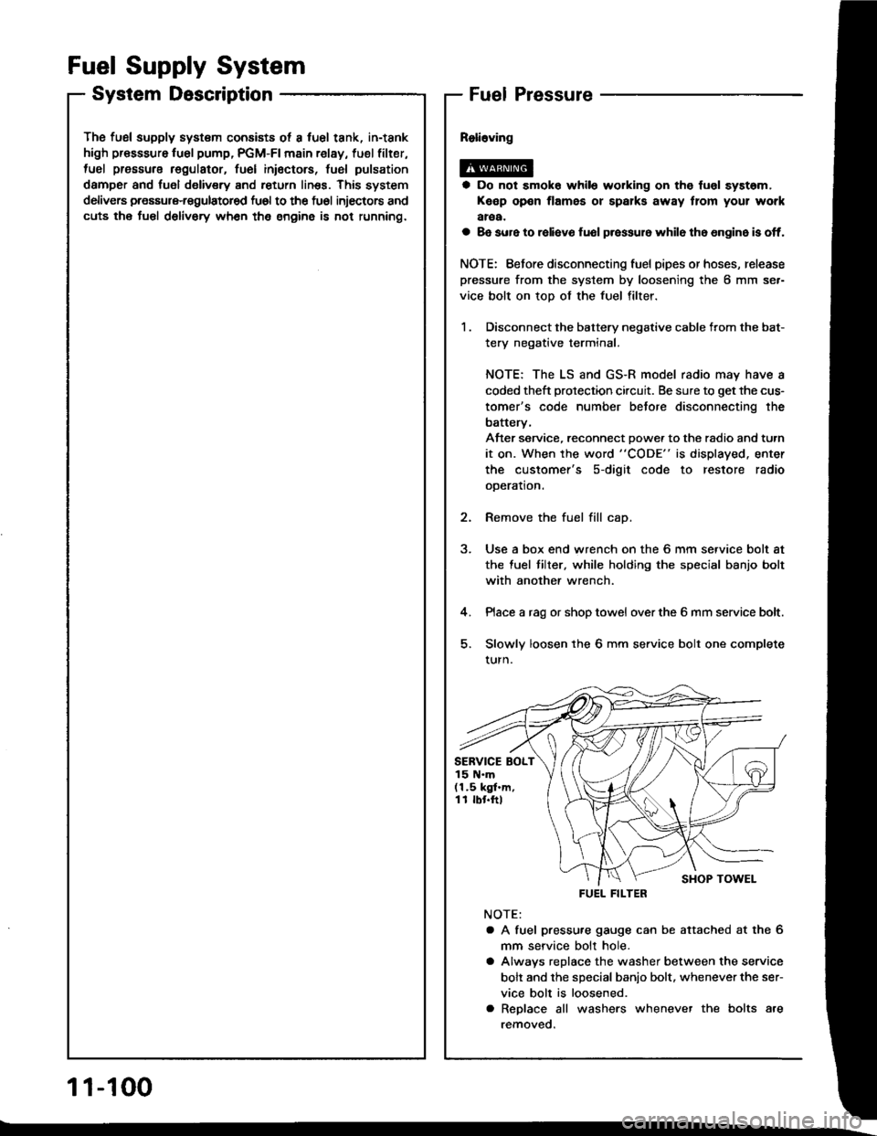
The fusl supply system consists ot a fuel tank, in-tank
high presssure fu6l pump, PGM-FI main relay, fuel filter,
tuel pressure regulatot, fuel inioctors, fusl pulsation
damper and fuol delivery and return linss. This system
delivers pressure-regulatored fu6l to the fu6l injectors and
cuts the fuel delivory wh6n the engine is not running.
Fuel Supply System
System DescriptionFuel Pressure
a Do not smok6 while working on the fuol syst6m,
Keep open flames or spalks away tlom your work
aroa.
a 8e sure to raliavo fuol p.essur6 while th6 6n9in6 is off.
NOTE: Eefore disconnecting fuel pipes or hoses, release
pressure from the system by loosening the 6 mm se.-
vice bolt on top of the fuel filter.
1 . Disconnect the battery negative cable from the bat-
tery negative terminal.
NOTE: The LS and GS-R model radio may have a
coded theft protection circuit. Be sure to get the cus-
tomer's code number betore disconnecting the
batterv,
After service, reconnect Dowe. to the radio and turn
it on. When the word "CODE" is displayed. enter
the customer's s-digit code to restore radio
ooeration.
2. Remove the fuel fill cap.
3. Use a box end wrench on the 6 mm service bolt at
the fuel tilter, while holding the special banjo bolt
with another wrench.
4. Place a rag or shop towel over the 6 mm service bolt.
5. Slowly loosen the 6 mm service bolt one complete
turn.
NOTE:
a A fuel pressu.e gauge can be attached at the 6
mm seryice bolt hole.
a Alwavs replace the washer between the service
bolt and the special banio bolt. whenever the ser-
vice bolt is loosened.
a Replace all washers whenever the bolts are
removeo.
SERVICE BOLT15 N.m(1.5 kgf.m,11 rbr.ftl
FUEL FILTER
1 1-100
Page 298 of 1413
[":::,::-'
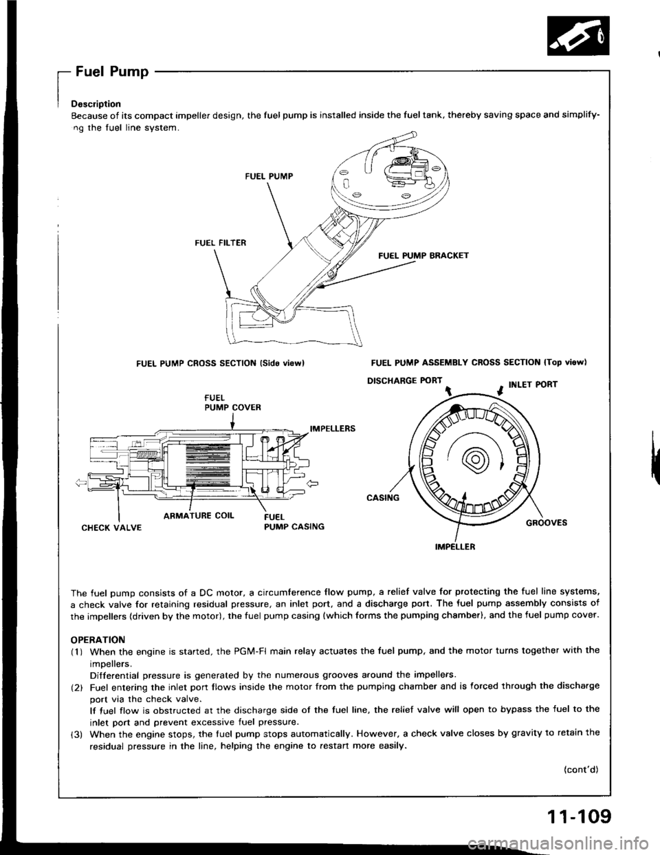
Eecause of its compact impeller design, the fuel pump is installed inside the fueltank, thereby saving space
ng the fuel line system.
FUEL PUMP
FUEL FILTER
FUEL PUMP BRACKET
FUEL PUMP CROSS SECTION lsido vi6rvl
IMPELLERS
CHECK VALVEPUMP CASING
The fuel oumo consists of a DC motor, a circumference flow pump, a relief valve for ptotecting the fuel lir
a check valve for retaining residual pressure, an inlet port, and a discharge port. The fuel pump assembly
the impellers (driven by the motor), the fuel pump casing {which forms the pumping chsmber), and the fuel p
OPERATION(1 ) When the engine is started. the PGi/t-Fl main relay actuates the fuel pump, and the motor turns togeth
impellers.
Differential pressure is generated by the numerous grooves around the impellers.
(2) Fuel entering the inlet porr flows inside the motor from the pumping chambe. and is forced through th
port via the check valve.
lf tuel flow is obstructed at the discharge side of the tuel line, the relief valve will open to bypass the
inlet port and prevent excessive fuel pressure.
(3) When the engine stops, the tuel pump stops automatically. However, a check valve closes by gravity t
residual pressure in the line, helping the engine to aestan more easily.
and simplify-
N lTop vi6w)
PORT
GROOVES
fuel line systems,
embly consists of
fuel pump cover.
together with the
rgh the discha.ge
ss the fuel to the
avitv to retain the
(cont'd)
PUMP COVER
FUEL PUMP ASSEMBLY CROSS SECTION
D|SCHARGE FORT ^ . tNLEr P
IMPELLER
11-109
Page 299 of 1413
Fuel Supply System
Fuel Pump (cont'dl
Tc.ting
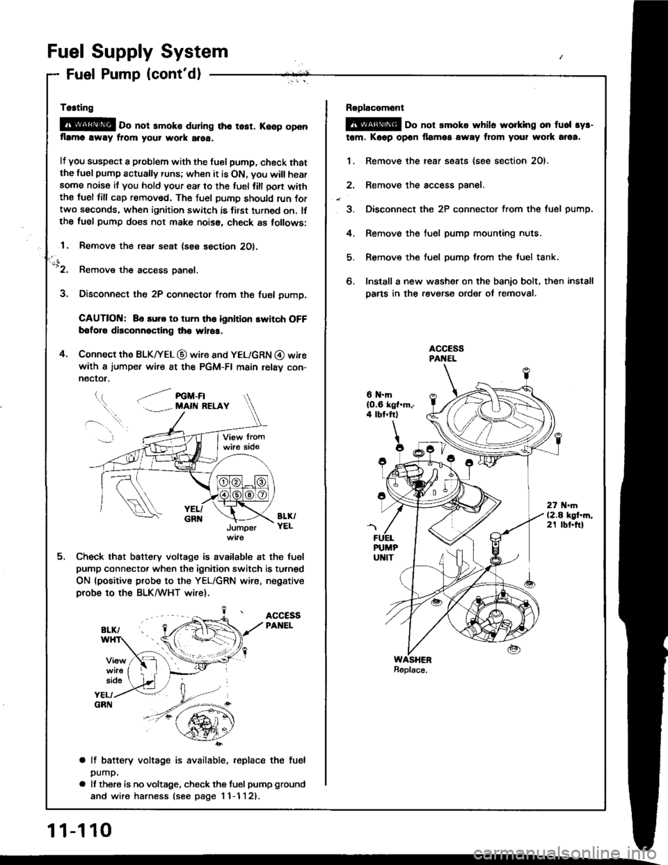
@E o" not smoko during tho tesr. Koop openflrmo away fiom your work area.
lf you susp€ct a problem with the tuel pump, check thatthe lusl pump actually runs; when it is ON, you will hearsome noise if you hold your ear to the luel lill oon withthe fuel fill cap remov6d. The fuel pumD should run fortwo seconds, when ignition switch is first turned on. llthe fuel pump does not make noiss, check as tollows;
1. Removo the rear seat (see section 2O).
-'2. Remove the access panel.
3. Disconnect the 2P connector from the fuel pump.
CAUTION: 86 lure to tum th6 ignition switch OFFbotor6 disconnoctlng th€ wilos,
4. Connect the BLK|yEL @ wire 8nd YEL/GRN @ wirewith a iumpe. wire 8t the PGM-FI main relav con-
nectot.
l.t, .--/ re -Fl. . MAll{ RELAY
BL&YELJumper
Check that battery voltage is available at the tuel
pump connector when the ignition switch is turned
ON (positive probe to the YEL/GRN wire, negativeprobe to ths BLK/WHT wire).
ACCESSPANEL
side
YEL/GRN
a lf battery voltage is available, replace the fuel
pump.
a It there is no voltage, check the tusl pump ground
and wire harness {see page I 1-1 l2).
11-110
Roplacomont
@ oo not smoks whilo worklng on fuel syr-
tem. Kaop opon llamos away from your wolk araa.
1. Remove the rear ssats {soe section 2O).
2. Remove the access oanel.
3. Disconnect the 2P connector from the fuel pump.
4. Remove the fuel pump mounting nuts.
5. Remove the fuel pump trom the luel tank.
6. Install a new washer on the banio bolt, then install
Darts in the revers€ order of removal.
6 N.mlO.6 kgl.m,.4 tbt.ftl
27 .m(2.4 kgt.m,21 tbt.ftl
Page 300 of 1413
PGM-Fl Main Relay
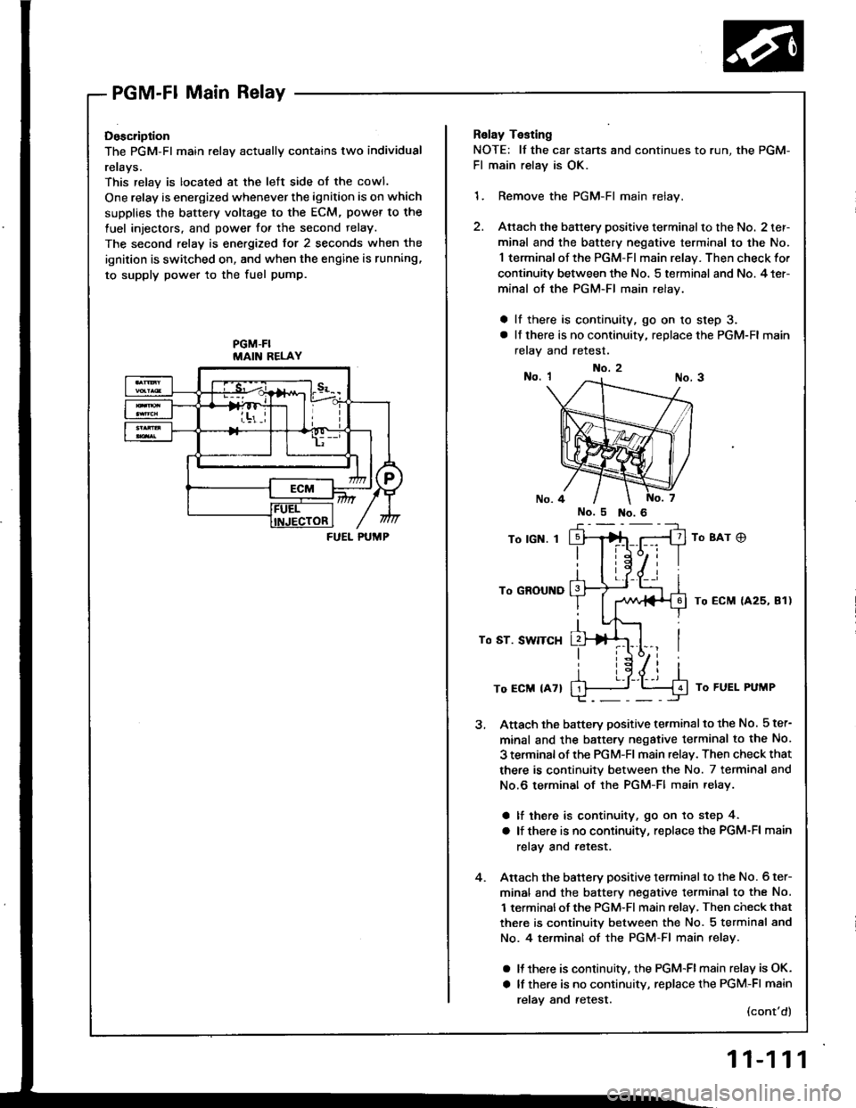
Doscription
The PGM-Fl main relav actuallv contains two individual
rerays.
This relay is located at the lett side of the cowl.
One relay is energized whenever the ignition is on which
supplies the battery voltage to the ECM, power to the
fuel injectors, and power for the second relay.
The second relay is energized for 2 seconds when the
ignition is switched on, and when the engine is running,
to supply power to the fuel pump.
PGM-FIMAIN RELAY
FUEL PUMP
Relay Testing
NOTE: lf the car stans and continues to r
Fl main relay is OK.
1. Remove the PGM-Fl main relay.
2. Attach the battery positive terminalto
minal and the battery negative termir
1 terminal of the PGM-FI main relay. T
continuity between the No. 5 terminal
minal of the PGM-FI main relay.
a lf there is continuity, go on 10 ste
a lt there is no continuity, replace the
relay and retest.
To lGN. I
To GROUND
To ST. SWITCH
To ECM {47}
Attach the battery positive terminalto
minal and the battery negative termil
3 terminal of rhe PGM-Fl main .elav. Tl
there is continuity between the No. ;
No.6 terminal of the PGM-Fl main re
a lf there is continuity, go on to st€
a lf there is no continuity, replace th€
relay and retest.
Anach the battery positive terminalto
minal and the battery negative termil
1 terminalof the PGM-Fl main relay, Tl
there is continuity between the No. :
No. 4 te.minal of the PGM-Fl main r
a It there is continuitv, the PGM-FI mi
a lf there is no continuity, replace th(
relav and retest.
No.2
run, the PGM-
nalto the No. 2 ter-
terminal to the No.
lay. Then check for
minal and No. 4 ter-
to step 3.
ce the PGM-Fl main
8Ar C)
ECM {425, 81)
J To FUEL PUMP
inalto the No. 5 ter-
terminsl to the No.
ay. Then check that
No. 7 terminal and
ain relay.
to step 4.
ce the PGM-Fl main
inal to the No. 6 ter-
terminal to the No.
ay, Then check that
No. 5 terminal and
nain relay.
-Flmain relay is OK.
ce the PGM-Fl main
(cont'd)
11-111
Page 301 of 1413
![HONDA INTEGRA 1994 4.G Owners Manual Fuel Supply System
PGM-Fl Main Relay (contdl
BLU
BLU/wHt
Bt-xNOTE:. M/T: Clutch pedal mustbe depressed.. A/T: Transmission in
N or E] position.
BLK/ YEL/YEL BLK
Tloubloshooting
{To page 11 113}
- Eng HONDA INTEGRA 1994 4.G Owners Manual Fuel Supply System
PGM-Fl Main Relay (contdl
BLU
BLU/wHt
Bt-xNOTE:. M/T: Clutch pedal mustbe depressed.. A/T: Transmission in
N or E] position.
BLK/ YEL/YEL BLK
Tloubloshooting
{To page 11 113}
- Eng](/img/13/6067/w960_6067-300.png)
Fuel Supply System
PGM-Fl Main Relay (cont'dl
BLU
BLU/wHt
Bt-xNOTE:. M/T: Clutch pedal mustbe depressed.. A/T: Transmission in
N or E] position.
BLK/ YEL/YEL BLK
Tloubloshooting
{To page 11 113}
- Engino will not sran.- Inspection oI PGM-FI main re-lay and rolay ha.n6!a.
Check lor continuitv between BLKterminal @ and body ground.
Rapair open in BLK wire botwoonPGM-FI main.el6y and GIO'l llo-catod at thormostot housingl.
Measure the voltage betweenYELMHT terminal @ and bodyground.- Roplaco th. ECU IECMI(15 Allus6 in tho under-hood fu!o/r6-lay box.- Ropair opan or short in theYEL/WHT wil6 botwosn thePGM-FI main rolay and the ECU
{EcMl 115 A} luso.
ls there battery voltage?
Turn the ignition switch ON.
Measure the voltage betweenBLK/YEL terminal @ and bodyground.- Reolac. ths No. 24 ACG {ALT}{lcl {15 A:81881 6ngino, 20A: Bl8Cl engin6) tuse in thoundor-dash fuso/rolaY box.- Ropaii op6n or rhon in thoBLK/YEL wiro botwoen thoPGM-FI main ielay and th€ No.24 ACG {ALT) flG} {'�15 A:818Bi ongine, 20 A: 818Cionginol fuso.Turn the ignition switch to theSTART position.
Measure the voltage betweenBLUMHT terminsl @ and bodyground.
- Replaco the l\lo. 18 STARTERSIGNAL {7.5 A} fuso in thoundor-dash fuaa/rolay box.- R6pai. open or short in thoBLU/WHT wire botweon thsPGM-FI main relay and tho No.1A STARTER SIGNAL I7.5 AIluse.
11-112
Page 302 of 1413
(From page 'l'l-1121
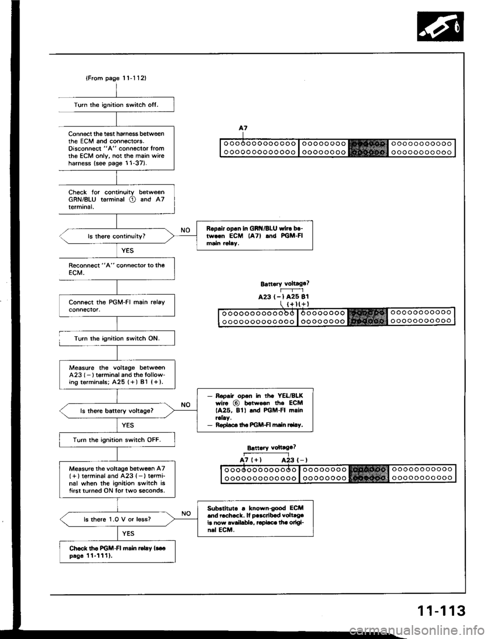
Roplir op.n in GRI{/BLU wirc bo-tw..n ECM lATl lnd PGM-FImain rolay.
Measure the voltag€ betweenA23l- ) t€rminal and the tollow-ing t€rminals; A25 (+ ) Bl (+ ).
- Ropair opon in rh. YEL/BLKwir. @ b€twoon the ECM1A25, 8tl .nd PGM-FI mrinraLy.- Roplsc. ttro PGM+I min ru4.y.
Turn the ignition switch OFF.
M€asure the voltage betw€en A7(+)torminal and A23 { - } t€rmi-nal when the ignition switch isfirst turned ON for two soconds.
Subrlitutc . known{ood ECM.nd 6chock. lf p..crib.d volt.g.ir now avallablo, rodaco lha otlgi-nsl ECM.
ls there 1.O V or l€ss?
Chod. th6 FGM-FI fioin relay {3o.p6g6 11-1111.
Turn the ignition switch off.
Connect the test harnoss b€tweenthe EcM and conneclors.Oisconnect "A" connector tromthe ECM onlv. not the main wireharness (see page 1'1-37).
Check forGRN/BLUlermrnal.
continuity betweenterminal O and A7
YES
Reconn€ct "4" connector to theECM.
Turn the ignition switch ON.
Bstt.ry vohago?r-----r_-lA23 (-l A25 Bl
Brttaiy voftago?
a7 (+l A23A23 (-)
11-113
Page 305 of 1413
Intake Air System
System Description
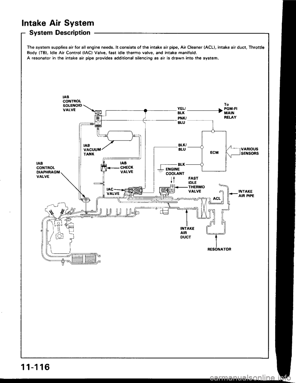
The system supplies air for allengine needs. lt consists of the intake air pipe, Air Cleaner (ACL), intake air duct, Throttle
Body (TB), ldle Air Control {lAC) Valve, tast idle thermo valve, and intake manifold.
A resonator in the intake air pipe provides additional silencing as air is drawn into the system.
nacot{TRoLSOLENOIDVALVE
To
ffi -------------+ i'"ii'i''RELAY
VARIOUSSENSORS
IABCONTROLDIAPHRAGMVALVE
-BLK--L EI{GINE- cooLnnt
tFASTIDLETHERMOVALVE
U
INTAKEAIR PIPE
INTAKEAIRDUCT
11-116
Page 312 of 1413
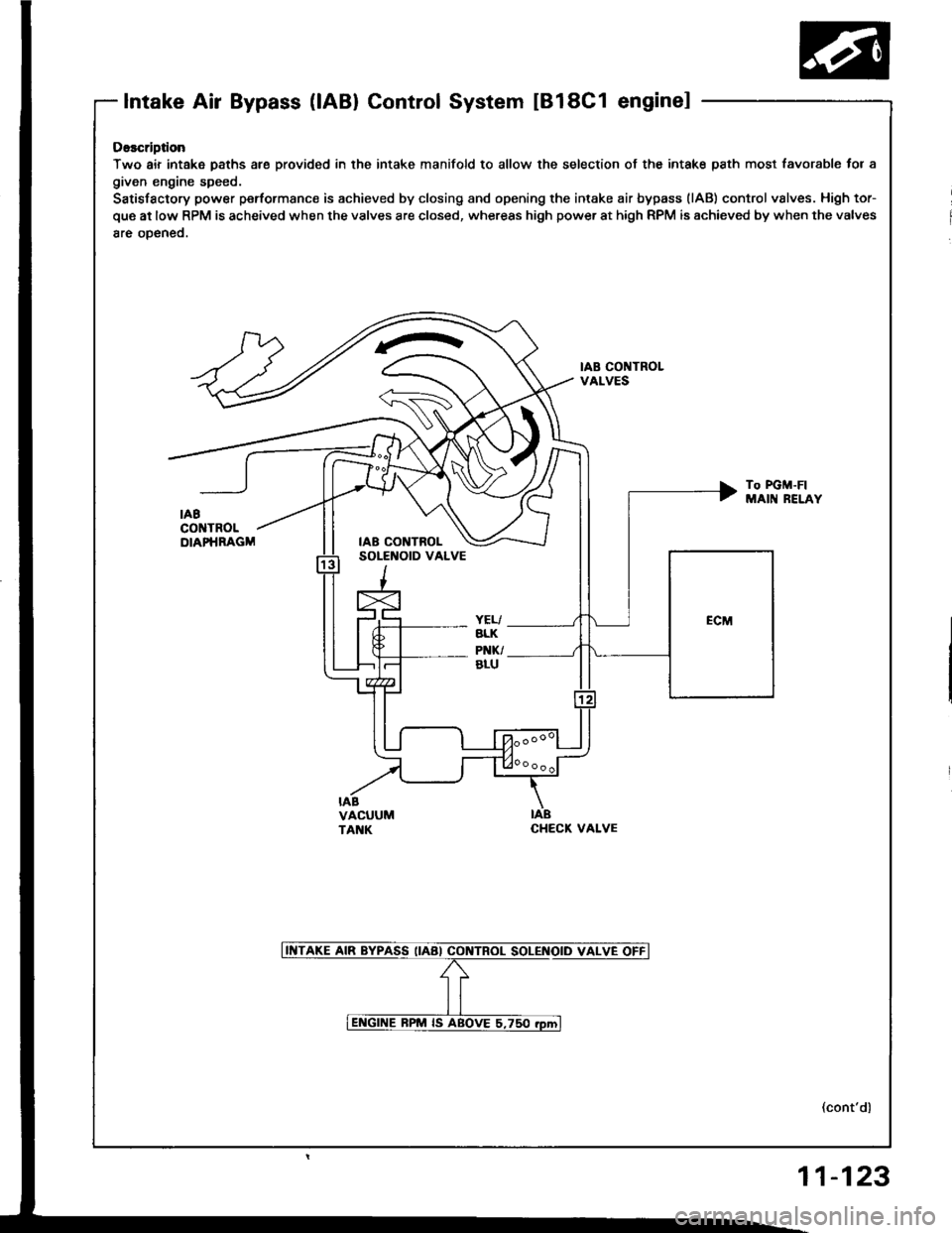
Intake Air Bypass (lABl Control System tBl8C1 enginel
Osscription
Two air intake paths are provided in the intake manifold to allow the selection of the intak€ path most favc
given engine speed.
Satisfactory power peformanc€ is achieved by closing and opening the intake air bypass (lAB) control valve!
que at low RPM is acheived when the valves are closed, whereas high power at high RPM is achieved by when
8re oDeneo.
IAB CONTROLVALVES
To PGM-FIMAIN RELi
IABCHECK VALVE
t favorabl€ for a
vslves. High tor-
when the valves
RELAY
(cont'dl
11-123