dashboard HONDA INTEGRA 1994 4.G Owner's Guide
[x] Cancel search | Manufacturer: HONDA, Model Year: 1994, Model line: INTEGRA, Model: HONDA INTEGRA 1994 4.GPages: 1413, PDF Size: 37.94 MB
Page 1176 of 1413
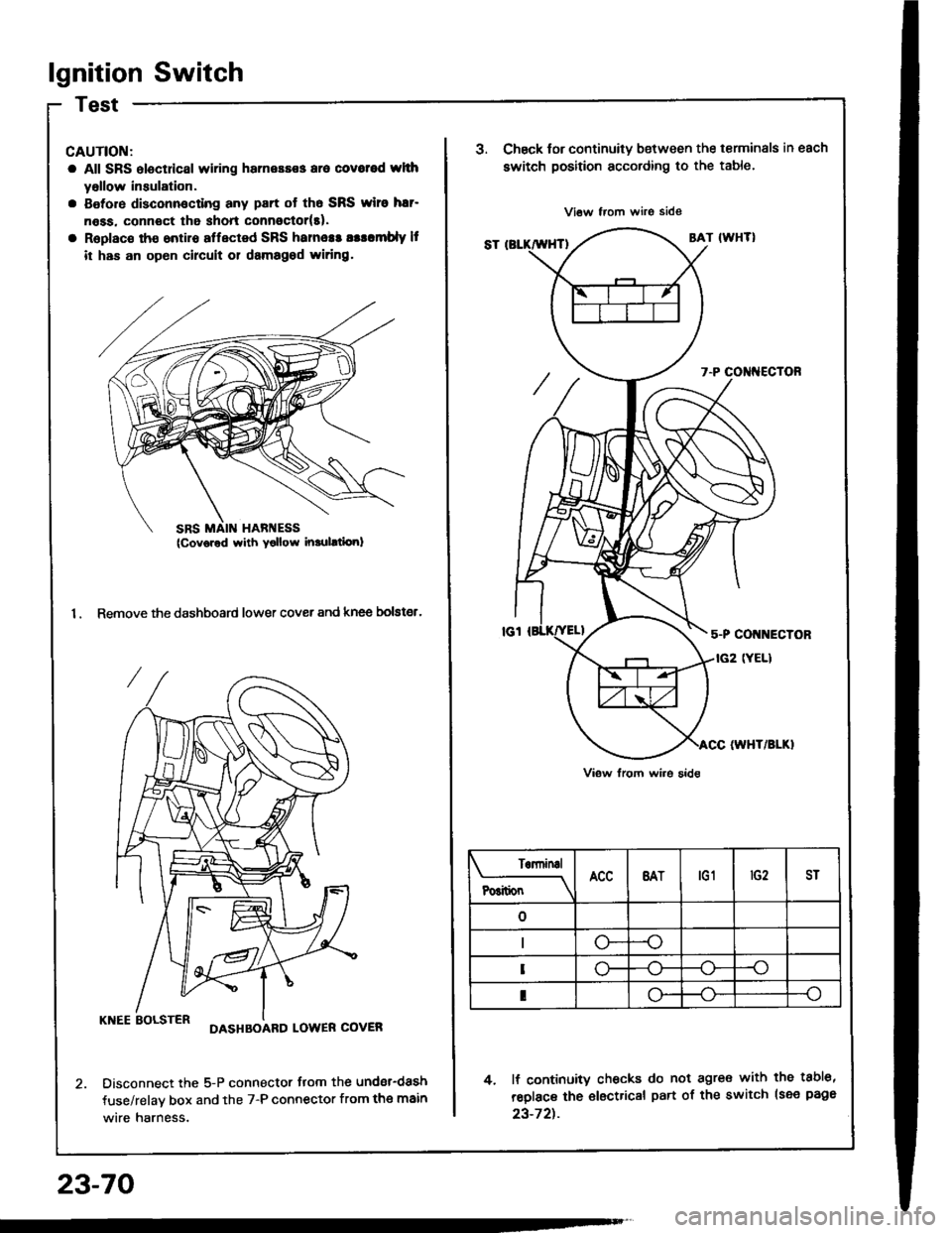
lgnition Switch
CAUTION:
a All SRS electdcal wiring harnessss aro covotod whh
yollow insulation.
a Botore disconnocting any part ot th6 SRS wiro har-
n6ss. connoct tha shon connoctor(t).
a Replac€ tho ontiro affected SRS hames! asllmbly It
it has an op6n circuit 01 damagod widng.
1. Remove the dashboard lower cover and knee bolster.
KNEE BOLSTERDASHBOARD LOWER COVER
Disconnect the 5-P connector flom the undsr-dash
fuse/relav box and the 7-P connector from the main
wire harness.
23-70
SRS MAIN HARI{ESS(Cov6red with Yollow inrulltiori)
J.Chsck tor continuity b€tween the terminals in each
switch position according to the table.
4. lf continuity checks do not agre€ with the tabl6,
reolace the €lectrical part of the switch lsee page
23-72t.
Terninal
P6itionBATtG1ST
--o
o-
I
Page 1177 of 1413
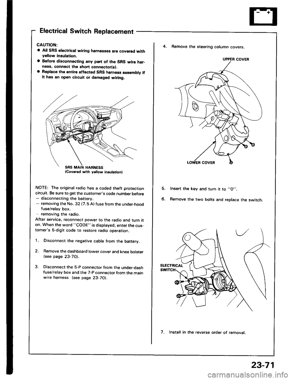
Electrical Switch Replacement
a All SRS €lectric8l wiring hamosses ar€ covorsd withyellow insulation,
a Befora disconnecting any pan of tho SRS wilo har-neas. connect the short connoctor(sl.a R6place the entire attect6d SFS harness assombly ifit has an opon circuit 01 damaged wiling.
NOTE: The original radio has a coded theft protection
circuit, Be sure to get the customer's code number before- disconnecting the battery.- removing the No. 32 (7.5 Al fuse from the under-hoodluse/relay box.- removang the radio.
After service, reconnect power to the radio and turn iton. When the word "CODE" is displayed, enter the cus-tomer's 5-digit code to restore radio ope.ation.
1. Disconnect the negative cable from the batery.
2. Remove the dashboard lower cover and knee bolster
{see page 23-70).
3. Disconnect the 5-P connector from the under-dashfuse/relay box and the 7-P connector from the mainwire harness (see page 23-70).
E
4. Remove the steering column covers.
Insert the key and turn it to ,,O',.
Remove the two bolts and replace the switch.
UPPER COVER
7. Install in the reve.se orde. of removat.
23-71
Page 1184 of 1413
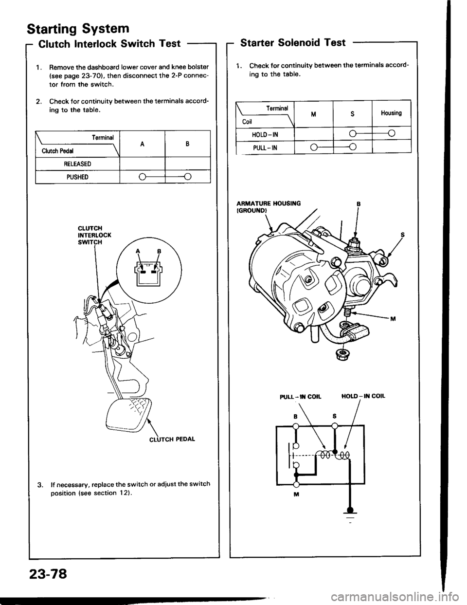
Starting System
Clutch Interlock Switch Test
1 . Remove the dashboard lower cover and knee bolster
(see page 23-70), then disconnect the 2-P connec-
tor from the switch.
2. Check tor continuity between the terminals accord-
ing to the table.
lf necessary. replace the switch or adjust the switch
oosition (see section 12).
Starter Solenoid Test
1. Check for continuitv between the tetminals accotd-
ing to the table.
HOLD - |l{ COIL
23-78
Tsrminal
CoilMDHousing
HOLD- INo----c
PULL- INo----.oClutch Pedal
T€rminalAB
RELEASED
PUSHEDoo
Pt LL- tt{ coll
Page 1234 of 1413
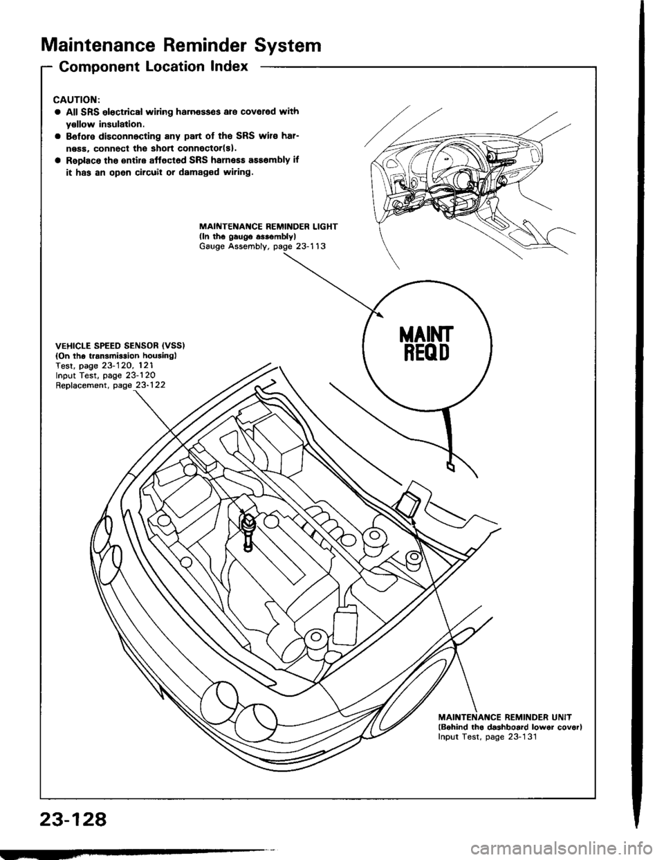
Maintenance ReminderSystem
Gomponent Location Index
23-128
CAUTION:
a All SRS eloctrical wiring haln€sses are coveled with
y€llow insulation.
a Bsfore disconnocting any part of the SRS wire har-
ne6a, connect tho shon connoctor(s).
a Replace the entire affoctod SRS hsrness ass6mbly if
it has an open circuil or damag€d wiring.
MAINTENAf{CE REMINDER LIGHT(ln th6 gaugo 63.smblylGauge Assembly. page 23-113
VEHICLE SPEED SENSOR {VSS){On the t.ansmirsion houainglTest, page 23-120, 121Input Test, page 23-120Repfacement, page 23-122
MAINTENANCE REMINDER UNITlBohind tho dashboard lowor covor)Input Test, page 23-131
MAINT
REOD
Page 1235 of 1413
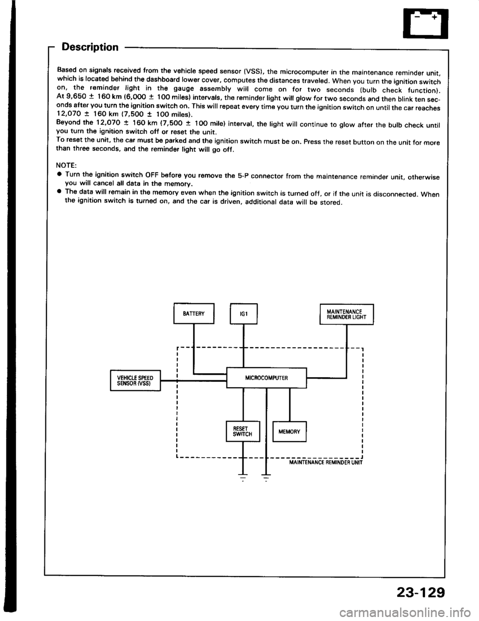
Description
Based on signals recaived trom the vehicle speed sensor (VSS), the microcomputer in the maintenance remande, unit,which is located behind the dashboard lower cover, computes the distances traveled. When you turn the ignition switchon, the reminder light in the gauge assembly will come on for two seconds (bulb check tunction).Ar 9,650 t 160 km (6,000 t lOo miles) intervals, the reminder light witl gtow for two seconds and then btank ten sec-onds att€r you turn the ignition switch on. This will repeat every time you turn the ignition switch on until the car reaches12,O7O ! 160 km (7,500 1 10O mites).Beyond the 12,O7O ! 160 km (7,500 t IOO mite) interval, the tight will continue ro gtow after the butb check untilyou turn the ignition switch off or reset the unit.To reset the unit, the car must be pa.ked and the ignition switch must be on. Press the reset button on the unit for mo.ethan three seconds, and the reminder tight will go otf.
NOTE:
a Turn the ignition switch OFF b€fore you r€move the 5-P connector from the maintenance reminder unit. otherwiseyou will cancel all data in the memorv.a The data will remain in the memory even when the ignition switch is turned ofJ, or if the unit is disconnected. Whenthe ignition switch is turned on, and the car is driven. additional data will be stored.
-----------------lMAINTENANCE REMINDEN UN|T
sEt{son tvss
23-129
Page 1240 of 1413
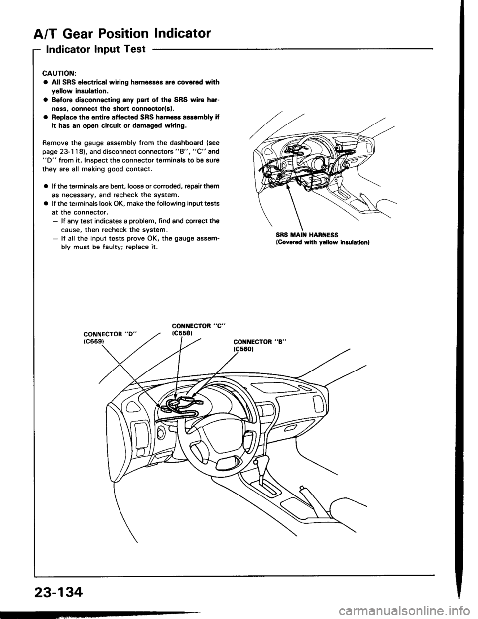
A/T Gear Position Indicator
Indicator Input Test
CAUTION:
a All SRS electrical widng harn6ssos ara cov6r6d whh
yellow insulation.
a Before disconnecting any part ot the SRS wiro hEr-
ness. connect the shon connoctolls).
a Replace the entire affectod SRS harnosr assombly il
it has an op€n circuit or damaged wiring.
Remove the gauge assembly from the dashboard (see
page 23- l 1 8), and disconnect connectors "8", "C" and"D" from it. lnsoect the connecto. terminals to be sure
they are all making good contact.
a lf the terminals are bent. loose or corroded, repair them
as necessary, and recheck the system.
a lf the terminals look OK, make the following input tests
at the connector.- lf any test indicates a problem, find and corect the
cause, then recheck the system.- lf all the input tests prove OK, the gauge assem-
bly must be taulty; replace it.
CONI{ECTOR "8"
SS
23-134
Page 1248 of 1413
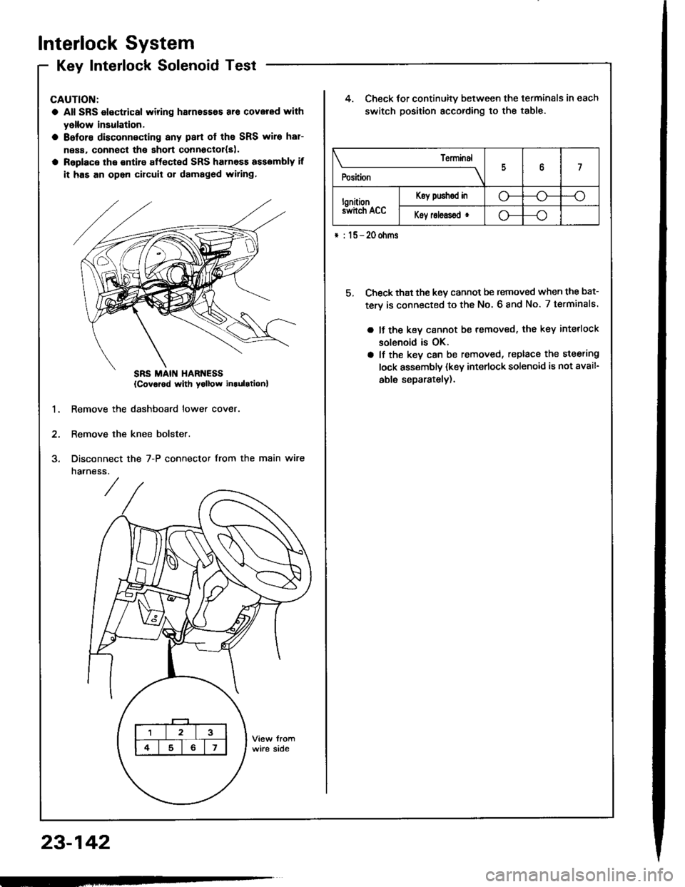
Interlock System
Kev Interlock SolenoidTestKey IntenocK Dorenoro I esr -
CAUTION:
a All SRS electrical wiring harnesses ar€ covered rYith
yollow insulation.
a 8eforc disconnecting any pan of the SRS wire har-
ness. connecl tha short connoclol{s|.
a Raplace the ontire affected SRS harness assembly if
it has an opon circuit or damaged wiring,
4. Check for continuitv between the terminals in each
switch position according to the table.
5, Check that the key cannot be removed when the bat-
tery is connected to the No. 6 8nd No. 7 terminals.
a It the kev cannot be removed, the key interlock
solenoid is OK.
a lf the key can be removed, replace the steering
lock assembly (key interlock solenoid is not avail-
able separately).
1.Remove the dashboard lower cover
Remove the knee bolster.
Disconnect
narness.
the 7-P connector from the main wire
\______________rry
Position7
lonitionS hch Acc
Koy push€d ino---o
Koy roleEsod r--o
* : l5-20ohms
{Covorod with yollow inlulrtionl
23-142
Page 1256 of 1413
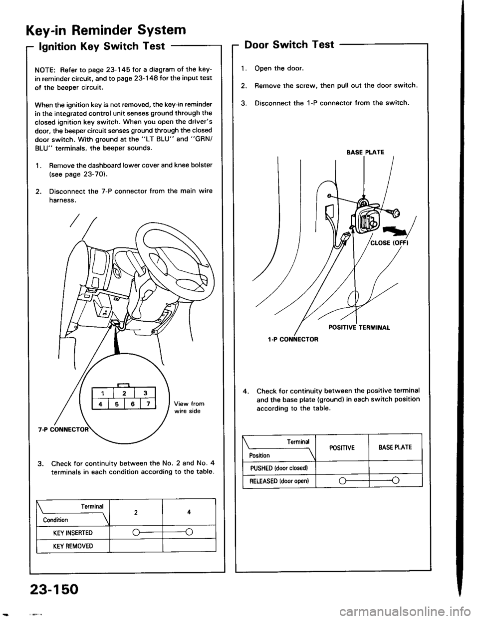
Key-in Reminder System
lgnition Key Switch Test
NOTE: Refer to page 23-145fot a diagram of the key-
in leminder circuit, and to page 23-148 Jor the input test
ol the beeper circuit.
When the ignition key is not removed, the key-in reminder
in the integrated control unit senses ground through the
closed ignition key switch. When you open the driver's
door, the beeper circuit senses ground through the closed
door switch, With ground at the "LT BLU" and "GRN/
BLU" terminals, the beeper sounds.
1 . Remove the dashboard lower cover and knee bolster
(see page 23-70).
2. Disconnect the 7-P connector from the main wire
harness.
Check for continuity between the No. 2 and No. 4
terminals in each condition acco.ding to the table.
l.
Door Switch Test
Open the door.
Remove the screw, then pull out the door switch.
Disconnect the 1-P connector from the switch.
4. Check lor continuity between the positive terminal
and the base plate (ground) in each switch position
according to the table.
BASE PLATE
Position
TerminalPOSITIVEBASE PLATE
PUSHED {door closedl
RELEASED ldoor o!en)oo
Terminal
Condition
4
KEY INSERTED--o
KEY REMOVED
23-150
Page 1257 of 1413
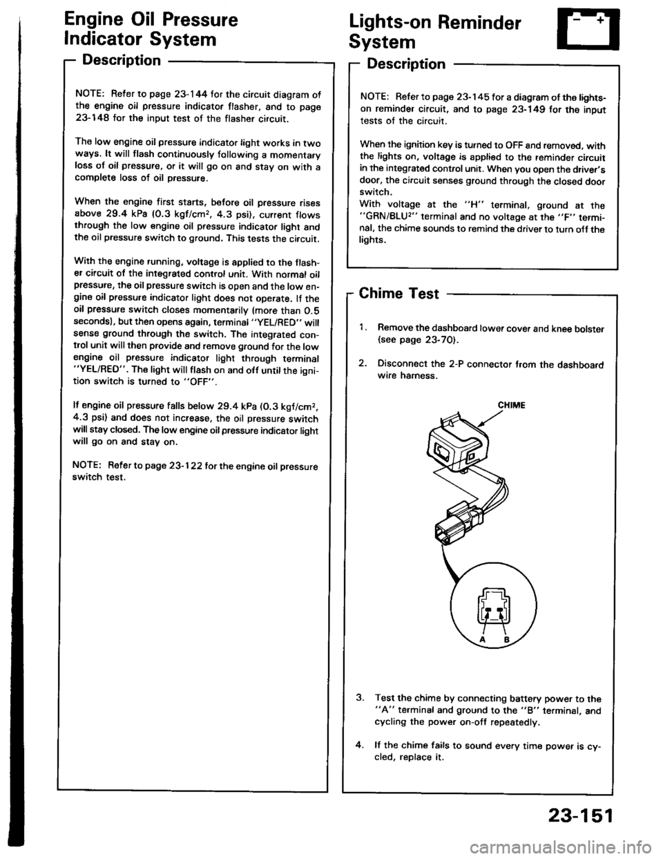
Engine Oil Pressure
Indicator System
Description
NOTE: Reter to page 23-144 tor the circuit diagram otthe engine oil pressure indicator flasher, snd to page
23-148 lor the input test of the flasher circuit.
The low engine oil pressure indicator tight works in twoways. lt will flash continuously following a momentaryloss of oil pressure, or it will go on and stay on with acomplete loss of oil pressure.
When the engine first starts, before oil Dressure risesabove 29.4 kP8 10.3 kgf/cmr, 4.3 psi), current flowsthrough the low engine oil pressure indicator light andthe oil pressure switch to ground. This tests the circuit.
Wilh the engine running, voltage is applied ro the ftash-er circuit of the integrated control unit. With normal oilpressure, the oil pressure switch is open and the low en-gine oil pressure indicator light does not operate. lf theoil pressure switch closes momentarily (more than O.5secondsl, but then opens again, terminal "yEL/RED,'will
sense ground through the switch. The integrated con-trol unit willthen provide and remove ground for th€ lowengine oil pressure indicator light through terminal"YEL/RED". The light will flash on and olf until the igni-tion switch is turned to "OFF".
lf engine oil pressure falls below 29.4 kPa (O.3 kgJ/cmr,4.3 psi) and does not increase, the oil pressure switchwillstsy closed. The low engine oilpressure indicator lightwill go on and stav on.
NOTE; Refer to page 23-122lot the engine oil pressure
switch test.
Lights-on Reminder
System
Description
Chime Test
Remove the dashboard lower cover and knee bolster
{see page 23-70).
Disconnect the 2-P connector t.om the dashboardwire hamess.
Test the chime by connecting battery power to the"A" te.minal and ground to the "B" terminal, andcycling the power on-off repestedly.
lf the chime fails to sound every time power is cy-cled, reDlace it.
NOTE: Refer to page 23-145 tor a diagram of the lights-
on reminder circuit, and to page 23-149 for the input
tests of the circuit.
When the ignition key is turned to OFF 8nd removed. withthe lights on, voltage is apptied to the reminder circuitin the integrat€d control unit. When you open the driver,sdoor, the circuit senses ground through the closed doorswitch.
With voltage at the "H" terminal, ground at the"GRN/BLU2" terminal and no voltage at the ,,F,' termi-nal, the chime sounds to remind the driver to turn oJf thelights.
CHIME
23-151
Page 1262 of 1413

Lighting System
Daytime Running Lights Control Unit Input Test (Canada)
CAUTION:
a All SRS eloc{dcal wi ng harn€sses are covelod with
yollow insulation.
a Boforo dbconnocting any psrt of the SRS wir€ h8r-
noss, connoct tho shon connector(s).
a Roplace the entire affected SRS harness assombly it
it has an opon Gilcuit or damagod wifng.
1 . Remove the dashboard lower cover and knee bolster.
2. Disconnect the connectors from the daytime running
lights control unit.
3. Insoect the connectof and socket terminals to be
sure they are all making good contact.
a ll the terminals are bent, loose or coroded, repair
them as necessary. and recheck the system,
a lf the terminals look OK, make the following in-
put tests at the connector,- lf any test indicates a problem, find and cor-
.ect the cause, then recheck the system.- ll allthe input tests prove OK, the control unit
must be taulty; replace if
4-P CONI{ECTOR
WHT/RED
YEL/ALK
8-P CONNECTOR
GRN/RED
WHTA'EL
23-156
View from wire sideVi6w from ware side
RED/GRI{