dashboard HONDA INTEGRA 1994 4.G Service Manual
[x] Cancel search | Manufacturer: HONDA, Model Year: 1994, Model line: INTEGRA, Model: HONDA INTEGRA 1994 4.GPages: 1413, PDF Size: 37.94 MB
Page 1264 of 1413
Lighting System
Combination Light/Turn Signal Switch Test
CAUTION:
a Atl SRS Oloctricsl wiring harnesses ar6 covered with
yellow insulation.
a Bslor€ disconnecting any pan ot the SRS wire har-
ness, connact the short connsctollsl.
a Replace the sntire aftectad SRS harne$ assembly if
it has an opon circuit or damagod wiring.
1. Remove the dashboard lower cover and steering
column covers (see page 23-71).
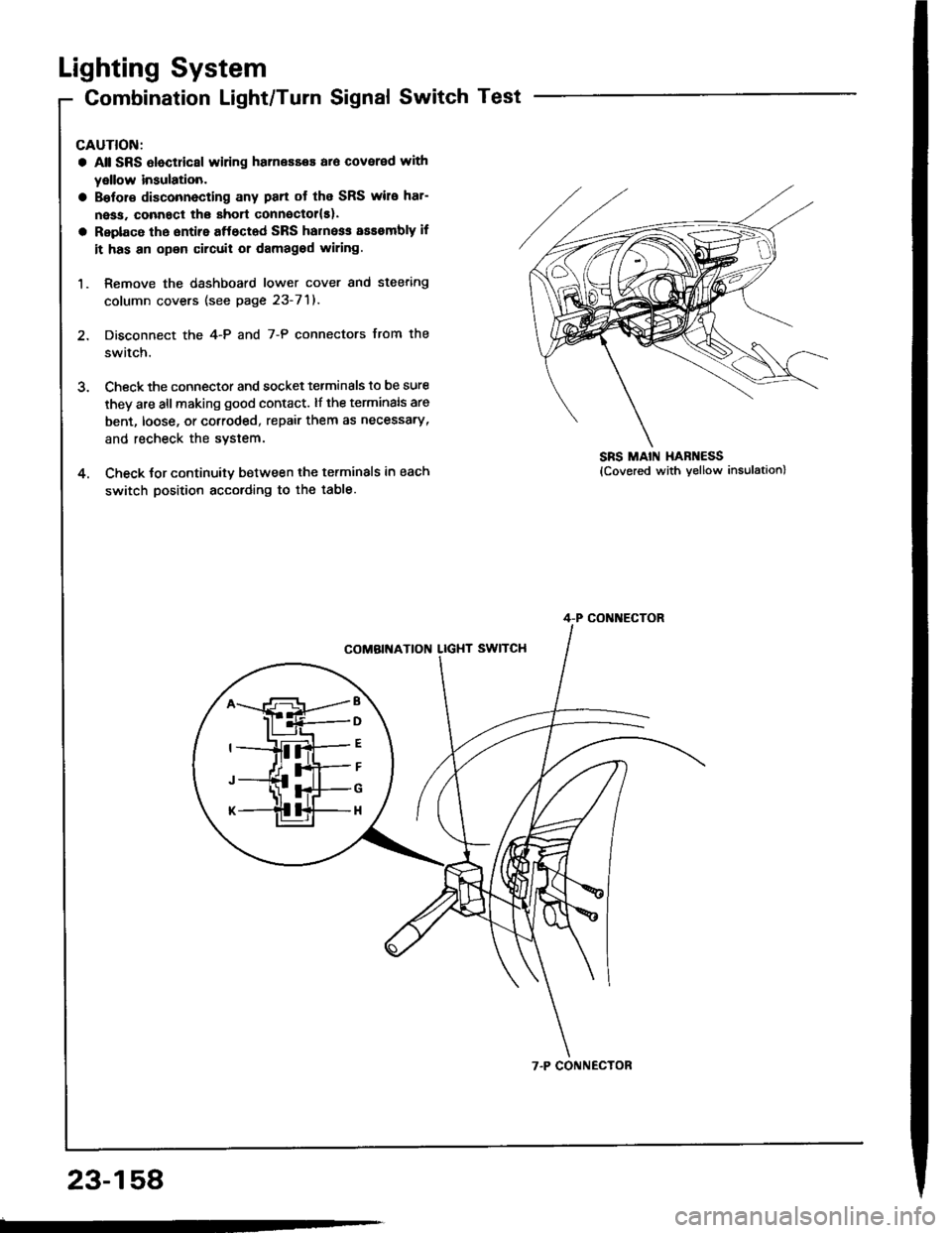
2. Disconnect the 4-P and 7-P connectors from the
switch.
3. Check the connector and socket tetminals to be sure
they are all making good contact. lf the terminals are
bent, loose, or cotroded, repair them as necessary,
and recheck the system.
4. Check tor continuitv between the terminals in each
switch position according to the table.
SRS MAIN HAR ESS
B
D
G
H
4-P CONI{ECTOR
7.P CONNECTOR
23-158
Page 1277 of 1413
Controller Input Test
NOTE: 8e careful not to damage the controller and the
instrument panal.
1. Remove the instrument panel lrom the dsshboard
{see page 23-1181.
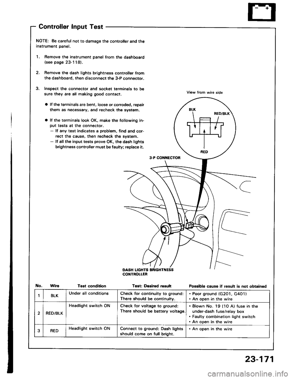
2. Remove the dash lights b.ightness controller {rom
the dashboard. then disconnect the 3-P connector.
Inspect the connector and socket terminals to be
sure they are all making good contact.
a lf the terminals are bent. loose o. corroded, repsir
them as necessary, and recheck the system.
a It the terminals look OK, make the tollowing in-
Dut tests at the connector.- lf any test indicates a problem, find and cor-
rect the cause, then recheck the system.- lf all the input tests prove OK, the dash lights
brightness controller must be faulty; replace it.
View from whe side
Possible causo it resull is not obtained
3-P CON[{ECTOR
OASH LIGHTSCOI{TROLIER
WireTost conditionTogt: Dasired resuh
1BLKUnder all conditionsCheck for continuity to ground:
There should be continuitv.
. Poor ground (G20 l , G4O1). An open in the wire
RED/BLK
Headlight switch ONCheck Jor voltage to ground:
There should be battery voltage.
Blown No. 19 (1O A) tuse in the
under-dash fuse/relay box
Faulty combination light switch
An open in the wire
aREDHeadlight switch ONConnect to ground: Dash lights
should come on full bright.
. An open in the wire
23-171
Page 1304 of 1413
Clock
Replacement
CAUTION:
a Pry th6 clock out at th€ left sido,
a Be carsful not to damage the clock and the dashboE d
whon prying the clock out.
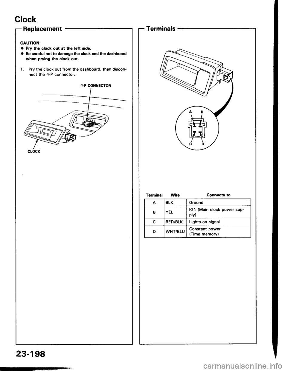
1. Pry the clock out from the dashboard, then discon-
nect the 4-P connector.
4-P COI{NECTOR
CLOCK
23-198
Terminals
Torminal WiroConnecta to
ABLKGround
YELplv){Main clock power sup-
RED/BLKLights-on signal
DWHT/BLUConstant power
(Time memory)
Page 1320 of 1413
Moonroof
Function Test
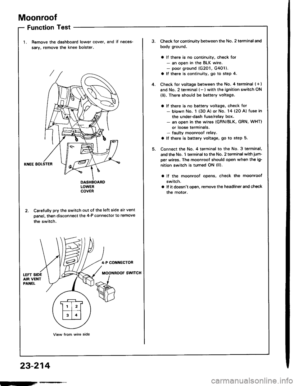
Remove the dashboard lower cover,
sarv, remove the knee bolste..
and if neces-
KNEE BOLSTER
DASHBOARDLOWERCOVER
2. Carefully pry the switch out of the left side air vent
panel, then disconnect the 4-P connector to remove
the switch.
4-P CONI{ECTOR
MOOi{ROOF SWITCH
View from wire side
.r--r
ll l2lf--T� --t
l314l
23-214
Check Jor continuity between the No. 2 terminal and
body ground.
a ll there is no continuity, check for- an ooen in the BLK wire.- poor ground (G201 , G4Ol ).
a lf there is continuity, go to step 4.
Check tor voltage between the No. 4 terminal ( + )
and No. 2 terminsl { - ) with the ignition switch ON
{ll). There should be battery voltage.
a lf there is no baftery voltage, check tot- blown No. 1 (3o Al or No. 14 {20 A) fuse in
the under-dash tuse/relay box.- an open in the wires (GRN/BLK, GRN, WHT)
or loose terminals.- faulty moonroof relay.
a lf there is battery voltage, go to step 5.
Connect the No. 4 terminal to the No. 3 terminal,
and the No. 1 terminal to the No, 2 terminal with jum-
per wires. The moonroot should open when the ig-
nition switch is turned ON (ll).
lf the moonroof ooens, check the moonroof
switch,
ll it doesn't open, remove the headlinet and check
the motor.
4.
Page 1321 of 1413
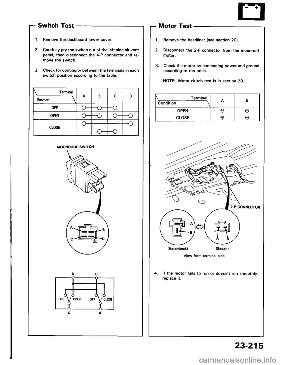
Switch Test
1, Remove the dashboard lower cover.
2. Carefully pry the switch out of the left side air vent
Danel, then disconnect the 4-P connector and re-
move the switch.
3. Check lor continuity between the terminals in each
switch position sccording to the table,
MOONROOF SWITCH
Motor Test
Remove the headliner (see section 20).
Disconnect the 2-P connector from the moonroot
moror.
Check the motor by connecting power and ground
according to the table.
NOTE: Motor clutch test is in section 20.
lHatchblckl (Scd!n)
View from terminal side
It the motor fails to run or doesn't run smoothly.
replace it.
4.
Torminal
P"ri i-
---__\AID
OFFG---o
OP€No---oG-
CLOSE
o---o
Te.minal
Condition -- ---------lAB
OPENo
CLOSE@
,l
rd\./ cLos€
Y
IOPEiIIOFF
23-215
Page 1352 of 1413
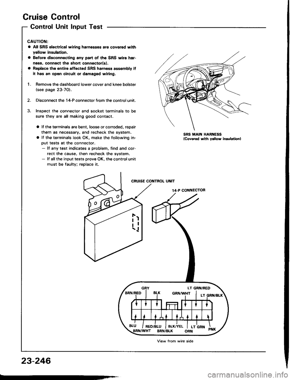
Cruise Control
Control Unit Input Test
CAUTION:
a All SRS olectrical wi ng harnessos are covored with
yellow insulation.
a Botore disconnecting any part of th6 SRS wire har-
neaa, connect the short connoctor(sl.
a Roplace the €ntir€ affectod SRS hamass assembly il
il has an opan circuit or damaged wifng.
1 , Remove the dashboard lower cover and knee bolster(see page 23-70).
2. Disconnect the 14-P connector trom the control unit.
Insoect the connector and socket terminals to be
sure they are all making good contact.
a lf the terminals are bent, loose or corroded, repair
them as necessary, and recheck the system.
a It the terminals look OK, make the following in-
Dut tests at the connector.- It any test indicates a problem, find and cor-
rect the cause. then recheck the svstem.- lf allthe input tesls prove OK, the control unit
must be faulty; replace it.
CRUISE CONTROL UNIT
14-P COI{NECTOR
SRS MAIN HARNESS
23-246
Viow from wire side
Page 1354 of 1413
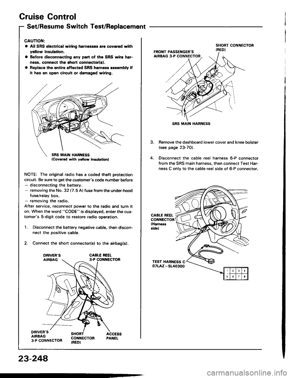
Cruise Gontrol
Set/Resume Switch Test/Replacement
CAUTION:
a All SRS ol6ct cal widng herne$a3 err covorod with
y6llow insulation.
a Bototo disconnecting any part ot tho SRS wiro h8r-
n6sa, connoct tho ghort connector(sl,
a Rsplaco the antire aftected SRS harness arsombly if
it has an op6n chcuit or damagod wiring.
NOTE: The original radio has a coded theft protection
circuit, Be sure to get the customer's code number befor€- disconnecting the battery.- removing the No. 32 (7.5 A) fuse from the under-hood
fuse/relay box.- removing the radio.
Afte, service, reconnect power to the radio and turn it
on. When the word "CODE" is displayed, enter the cus-
tomer's s-digit code to restore radio op€ration.
1 . Disconnect the battery negative cable, then discon-
nect the Dositive cable.
2. Connect the short connector(s) to the airbag(s).
DRIVER'SAIRBAG3-P CONNECTOR
SHORT ACCESSCON]TECTON PANEL(REDI
23-248
SRS MAIN HARNESS
3. Remove the dashboard lower cover and knee bolster(see page 23-70).
4. Oisconnect the cable reel harness 6-P connector
from the SRS main harness, then connect Test Har-
ness C onlv to the cable reel side of 6-P connector.
CABLE REELCONNECTORlHlrnoa!Eidol
Page 1356 of 1413
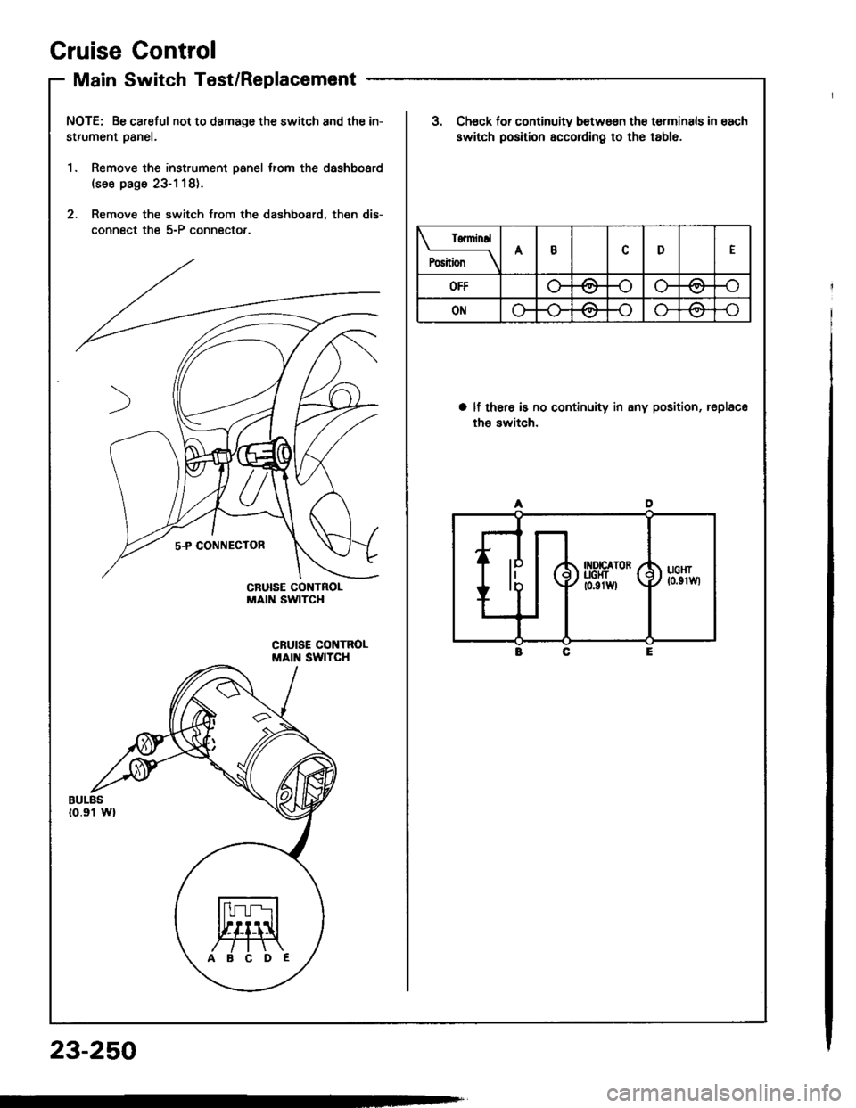
Cruise Gontrol
Main Switch Test/Replacement
NOTE: Be careful not to damage the switch and the in-
strument oanel.
1. Remove the instrument panel trom the dashboard(see page 23-1 18).
2. Remove the switch from the dashboard, then dis-
connect the 5-P connecto,.
ABCDE
23-250
Tenninrl
P".ii";--\ABD
OFF-oo-/a
ONAA-o\7
3. Ch6ck for continuity betwo€n the terminals in each
switch position according to the table.
a lf thera is no continuity in any position, replace
th€ switch.
A
rxorcaToR y'UCI{T [ (
to.grwl \) ucsr7 lo.grwl
E
Page 1375 of 1413
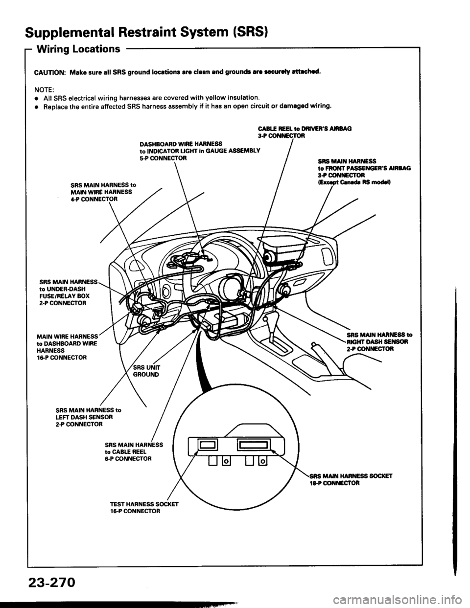
Supplemental Restraint System (SRSI
Wiring Locations
CAUnON: Make sure all SRS ground locrtion3 lrc clrln rnd ground3 tra |.curalv rltachad.
NOTE:
o Alt SRS electricsl wiring harnesses are covered with ysllow insulation.
. RsDlace the entire affected SRS harness assembly if it has an open circuit or damaged wiring.
CABIE REEL to DdrrEFS AnaAC3+ OOI{iECTOR
DASHBOARD WIRE HARNEi9to INDICATOB UGHT in GAUGE ASSEMBLY
5-P CONNECTOBaFs irA[t H^RiEssto FROiIT PASSEMIEFS Ana G3t coftf'Eclon
SRS MAIN HARNESS tO
MAIN WIRE HARNESS+P OONNECTOR
C. b Ra nod.ll
SnS Alt{ ll^ntc8s too sH SErson2+ OOt{tlEcT()R
SRS MAIN HARNESSto UNDER-DASHFUSE/RELAY BOX2"P @NNECTOR
MAIN WIRE HARNESSto DASHBOARD WIREHARNESSlGP CONNECTOR
SBS MAIN HARNESS toLEFT DASH SENSOR2.P CONNECTOA
23-270
Page 1383 of 1413
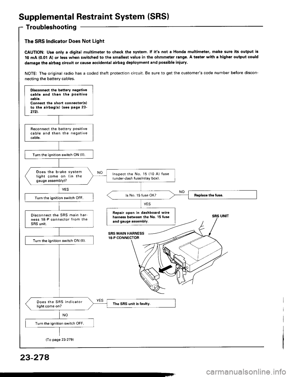
Supplemental Restraint System (SRS)
Troubleshooting
The SRS Indicator Does Not Light
CAUTION: Uss only a digital multimeter to check the system. lf it's not a Honda multimeter, make sure its output is
10 mA {0.01 Al or less when switched to the smallest value in the ohmmeter rang€. A tester with a highor ouiput could
damage the airbag circuit or cause accidental airbag deployment and possible iniury
NOTE: The original radio has a coded theft protection circuit. Be sure to get the customer's code number before discon-
necting the battery cables.
Dilconn6ct the battory negaiivecable rnd thon tho positive
cable.Connest the short connectorlslto tho airbaglsl (seo p6ge 23-272t.
R€connect the batterY Positivecable and then the negativecable.
Turn the ignition switch ON (ll).
Does the brake systemlight come on (in thegauge assembly)?
Inspect the No. l5 110 A) fuse(under-dash tuse/relay box).
ls No. 15 fuse OK?Turn the ignition switch OFF.
Repair open in dashboard wir6harness between the No. 15 tus€and gauge a3sombly.
Disconnect the SRS main har-ness l8-P connector from theSRS unit.
Turn the ignition switch ON (ll).
Does the SRS indicatorlight come on?The SRS unit is faully.
Turn the ignition switch OFF.
SRS UNIT
SRS MAIN HARNESS18.P CONNECTOR
Io page 23'2791
23-274