srs HONDA INTEGRA 1994 4.G Repair Manual
[x] Cancel search | Manufacturer: HONDA, Model Year: 1994, Model line: INTEGRA, Model: HONDA INTEGRA 1994 4.GPages: 1413, PDF Size: 37.94 MB
Page 1178 of 1413
lgnition Switch
Steering Lock Replacement
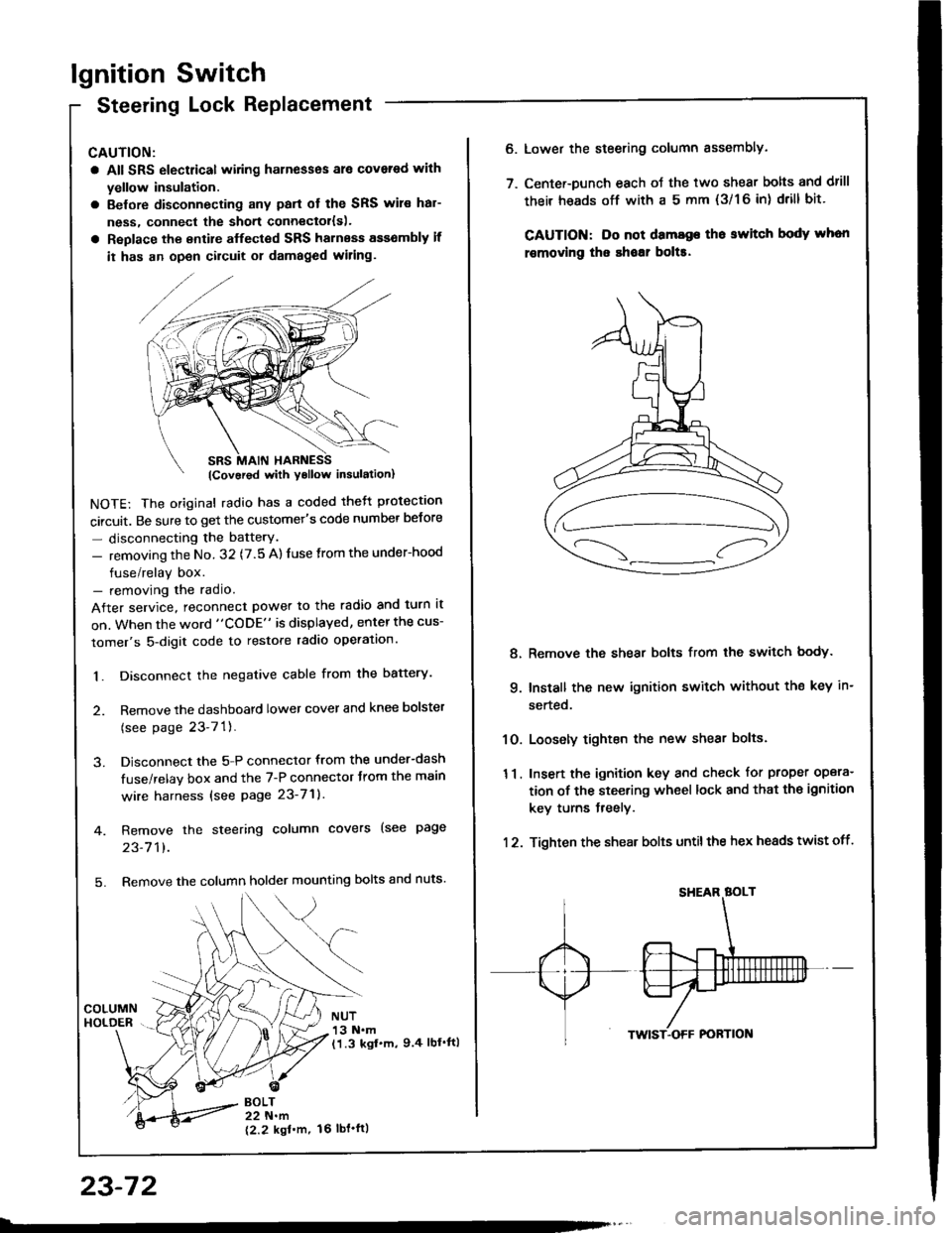
CAUTION:
a All SRS electrical wiring harnesses ale covsred with
yellow insulation.
a Belore disconnecting any parl ot the SRS wir€ hal-
ness, connecl the short connector{s).
a Replace the entire alfected SRS harness a$6mbly il
it has an open circuit or damaged wiring.
NOTE: The original radio has a coded thett protection
circuit. Be sure to get the customer's code number betore
- disconnecting the batterY.
- removing the No. 32 (7.5 A) fuse from the under-hood
fuse/relay box.- removing the radio.
After service, reconnect power to the radio and turn it
on. When the word "CODE" is displayed, enter the cus-
tomer's 5-digit code to restore radio operation.
1. Disconnect the negative cable from the battery.
2. Remove the dashboald lower cover and knee bolster
(see page 23-7'l ).
3. Disconnect the 5-P connector from the under-dash
fuse/relay box and the 7-P connector trom the main
wire harness {see page 23-71).
4. Remove the steering column covers (see page
23-711.
5. Remove the column holder mounting bolts and nuts'
BOLT22 N.m
12.2 kgl'm.
NUT13 N.m(1.3 kgf.m, 9.4 lbl'ftl
23-72
16 tbt.ftl
6. Lower the steering column sssembly.
7. Center-Dunch each oJ the two shear bolts and drill
their heads off with a 5 mm {3/1 6 in) drill bit'
CAUTION: Do not dama96 tho switch body whon
r€movlng the shoar bol$.
Remove the shear bolts from the switch body.
Install the new ignition switch without the key in-
serted.
Loosely tighten the new shear bolts.
Insert the ignition key and check for proper opera-
tion of the steering wheel lock and that th€ ignition
key turns freely.
Tighten the shear bolts untilthe hex heads twist off.
8.
q
10.
11.
12.
Page 1183 of 1413
5. Check lor 8n op€n in the BLKMHT wire circuit be-
tween the staner and ignition switch, and con-
nectors.
6. Check the ignition switch (see page 23-70).
7, On cars with automatic transmission, check the A/Tgear position switch (neutral position switchl and
connector. On cars with manualtransmission, check
the staner cut relay, clutch interlock switch, and
connectors.
NOTE: Check the No. 39 (5O A) fuse in the under-hood
fuse/relay box for the starter cut relay.
Check tor Woar and Damago:
The starter should crank the engine smoothly and stead-
ily. lf th€ startsr engages, but cranks the engine errati-
cally, remove it. Inspect the starter, drive gear, and
flywheel ring gesr for damage.
a Check the drive gear overunning clutch for binding
or slipping when the armature is rotated with the drivegear held. Replace the gesrs if damaged.
Check Cranking Voltago 8nd Current Draw:
Cranking voltage should be no less than 8.O volts.
Current draw should be no more than 360 amperes.
lf cranking voltag€ is too low, or current draw too high,
check for:
a Fully charged battery
a Open circuit in starter armature commutatot segments
a Starter armature dragging
a Shoned armature winding
a Excessive drag in engine
Chack Cranking rpm:
Engine spsod during cranking should be above 1O0 rpm.
lf spe6d is too low, ch€ck for:
a Loose battsry or starter teminals
a Excessively worn starter brushes
a Open circuit in commutator segments
a Dirty or damaged helical spline or drive gear
a Defective drive gear overrunning clutch
Chock StErtor Disongagomoni:
Press the clutch pedal allth€ way in (M/T), turn the ioni-
tion switch to "lll" and rolease to "11".
The starter drive gear should disengage from the tlywheel
ring gear. When you rolease the key.
lf the drive gear hangs up on th€ flywheel ring gear, check
for:
a Solenoid plunger and switch malfunction
a Dirty drive gear assembly or damaged overrunning
clutch
23-77
Page 1219 of 1413
Gauge Assembly
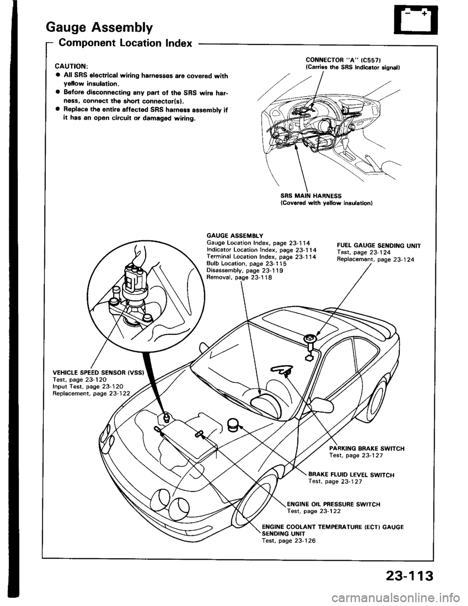
Component Location Index
CAUTION:
a All SRS electrical wiring harnosses are cov€rod withyellow insulation.
a Bofore disconnecting any prn ot th€ SRS wire har-ness, connect tho short connector(sl.a R€place th6 entirs affGcted SRS halne$ assembly ifit has an open circuit o? damaged wiring.
SRS MAIN HARNESS{Cov.r6d with yollow inrularionl
GAUGE ASSEMBLYGauge Location Index, page 23-114Indicator Location Index, page 23-1 14Terminal Location Index, page 23-114Bulb Location. page 23-'l 15Disassembly. page 23-1 19Removal, page 23-118
FUEL GAUGE SENDING UNtTTest, page 23'124Repfacemenr, page 23-124
VEHICLE SPEEO SENSOB IVSS}Test, page 23-120fnput Test. page 23-120Repfacement, page 23-122
PARKITTG BRAKE SWITCHTest, page 23-127
BRAKE FLUID LEVEL SWITCHTesr, page 23-127
EI{GINE OIL PBESSURE SWITCHTest, page 23-122
ENGINE COOLANT TEMPERATURE IECTI GAUGESENOING UNITTest, page 23-126
(C61'ios tho SBS indicator signal)
23-113
Page 1220 of 1413
Gauge Assembly
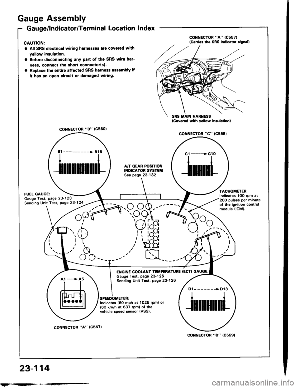
Gauge/lndicator/Terminal Location Index
CAUTIOI{:
a All SRS olectrical wiring harnessos aro covorod with
yellow insulation,
Belol€ disconnecting any part ot tho SRS wiro hat-
nesa. connoct the short connoctol(El.
Replaco th6 entire aff6cted SRS hamess sssombly lf
it has an open circuil or damagod widng.
co r{EcroR "c" (c558}
FUEL GAUGE:Gauge Test, page 23-123
Sending Unit Tost, page 23-124
23,-114
A/T GEAR POSIT|OIIDICATOR SYSTEISee pags 23-132
E GI[{E COOLAI{T TEIIPEFATURE IECTIc6uge TEst, p6g6 23-126Sending Unit Tsst, pago 23-126
TACHOMETER:Indicatos lOO rpm at20O puls€s per minul€of the ignition controlmodul€ llCM).
SPEEDOMETER:Indicates (60 mph 6i 1025 rpml or{60 km/h at 637 rem) of th€v€hicle spe6d sonsor lVSSl.
CoNNECTOR "8" (c5601
Bi ----------+ B16Cl ----+ClO
f',. /i)
)Y
-"b
\_./ \J \-___--
a1 -----> A5
Dl-------.>D13
col{]{ECTOR "D" (C5591
rtrF --
coNNECfOR "A" (C557)
Page 1221 of 1413
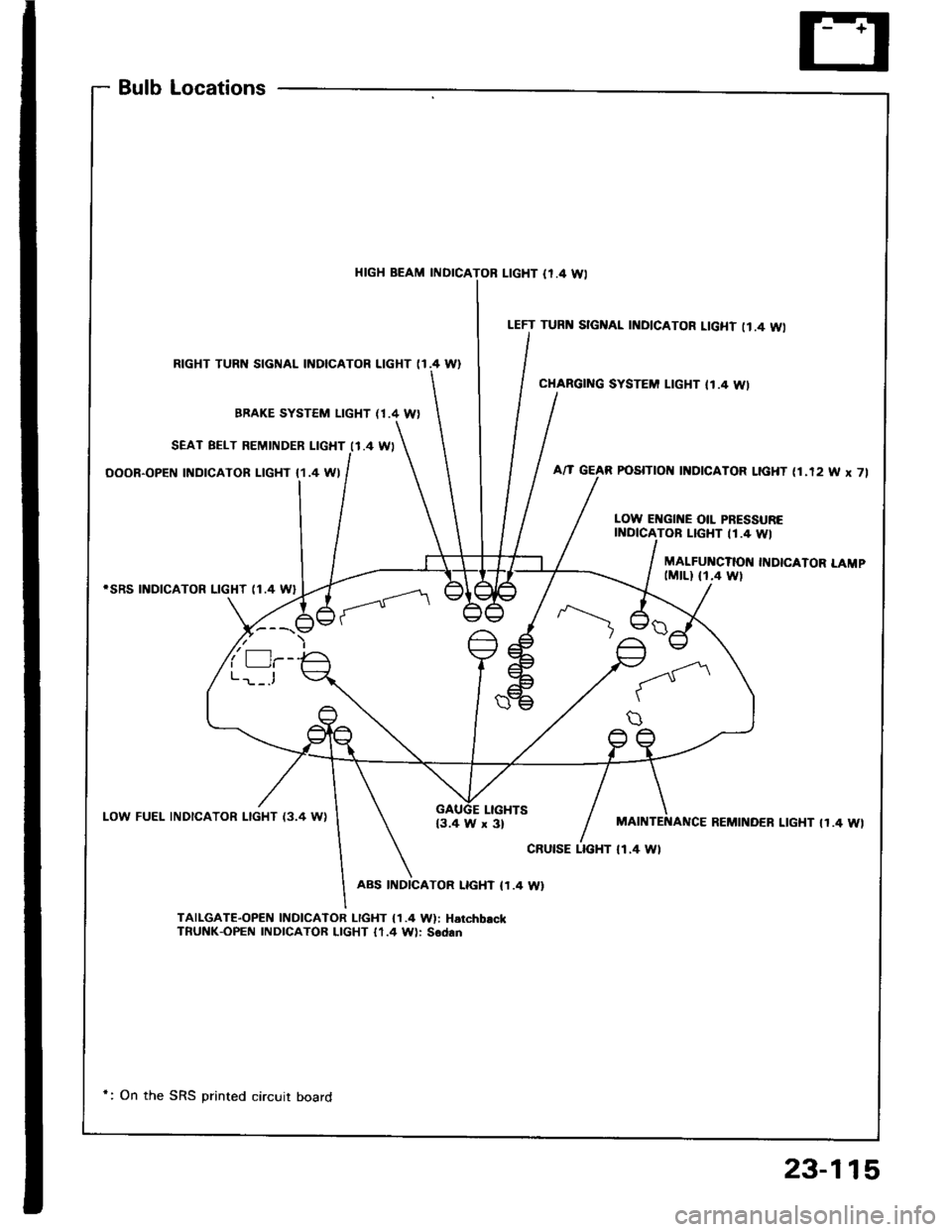
BulbLocations
HIGH BEAM INDICAL|GHT {r.4 Wl
RIGHT TURN SIGNAL INDICATOR LIGHT (I.4 W}
BBAKE SYSTEM LIGHT (1.4 W)
SEAT BELT REMINDER LIGHT I1.4 WI
OOOR-OPEN INDICATOR LIGHT {1.4 WI
iSRS INDICATOR LIGHT (1.4 W}
LOW FUEL INDICATOR LIGHT {3.4 WILIGHTS{3.4 W x 3}
ABS INDICATOR LIGHT (1.4 W}
TAILGAT€-OPEN INDICATOR I-IGHT {1.4 W): HarchbackTnUNK-OPEN INDICATOR LIGHT 11.4 W): Sodan
LEFT TURI{ SIGNAL INDICATOR LIGHT II.4 WI
CHARGING SYSTEM LIGHT II.4 WI
POSITIOII I]{DICATOR LIGHT (1.12 W x 7l
LOW EI{GII{E OIL PRESSURETOB LIGHT 11.4 WI
MALFUI{CTION INDICATOR LAMP(MrLl fi.4 wt
MAINTENANCE REMINOER LIGHT IT.4 WI
cRutsE LTGHT tl.4 Wl
*: On the SRS printed circuit board
23-115
Page 1224 of 1413
Gauge Assembly
Removal
CAUTION:
a All SRS electrical wiling harnesses ara cover6d with
yollow insulation.
a Eofore disconnecting any part ol the SRS wiro har-
n6ss, connoct lhe short connector(sl.
a Roplace tho entirs affocted SRS harneas assembly if
it has an open circuit 01 damaged wi.ing.
SBS MAIN HARI{ESS(Covor6d with Yollow in.ulationl
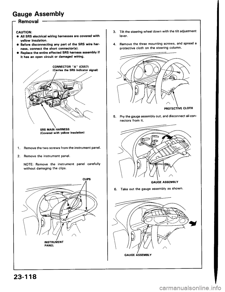
Remove the two screws lrom the instrument panel.
Remove the instrument panel.
NOTE: Remove the instrument panel careJully
without damaging the cliPs.
1.
2.
lcarrio. tho SRs indicolor 8ignal)
CLIPS
23-118
Tilt the steering wheel down with the tilt adjustment
tevet.
Remove the three mounting screws, and spread a
protective cloth on the steering column.
PROTECTIVE CLOTH
Pry the gauge assembly out, and disconnect allcon-
nectors from it.
GAUGE ASSEMBLY
Take out the gauge assembly as shown.o.
Page 1228 of 1413
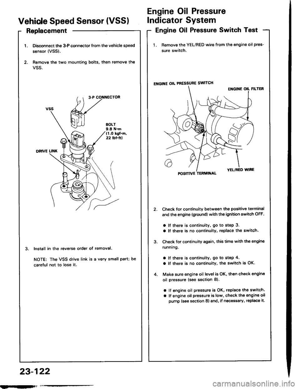
Replacement
Disconnect the 3-P connector trom the vehicle speed
sensor {VSS).
Remove ihe two mounting bolts, then remove the
VSS.
InstSll in the revsrse order of removal.
NOTE: The VSS drive link is a very small paru
caretul not to lose it.
Engine Oil Pressure
Vehide Speed Sensor (VSSIIndicator System
Engine Oil Pressure Switch Test
1. Remove the YEL/RED wile from the engine oil pres-
sure switch.
ENGI'{E OIL PRESSURE SWITCH
Check tor continuitv between the positive torminal
and the engine {gtound) with the ignhion swhch OFF.
a lf there is continuity, go to step 3.
a lf there is no continuity, replace the switch.
Check for continuity again, this time with th€ engine
runnrng.
a lf there is continuity, go to step 4,
a lf there is no continuity, the switch is OK.
Make sure engine oil level is OK, then check engin€
oil pressure (s€e section 8).
a lf engine oil pressure is OK, replace the switch'
a lf engine oil pressure is low, check the sngine oil
pump (see section 8) and, if necessary, replac€ it.
POSITIVE TERMII{AL
23-122
nlmlliitl
Page 1234 of 1413
Maintenance ReminderSystem
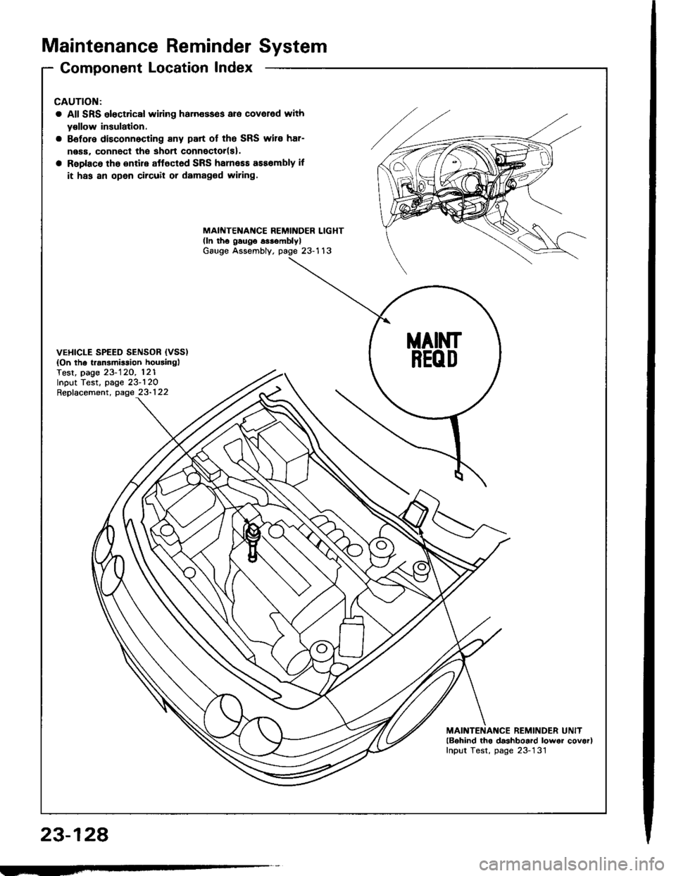
Gomponent Location Index
23-128
CAUTION:
a All SRS eloctrical wiring haln€sses are coveled with
y€llow insulation.
a Bsfore disconnocting any part of the SRS wire har-
ne6a, connect tho shon connoctor(s).
a Replace the entire affoctod SRS hsrness ass6mbly if
it has an open circuil or damag€d wiring.
MAINTENAf{CE REMINDER LIGHT(ln th6 gaugo 63.smblylGauge Assembly. page 23-113
VEHICLE SPEED SENSOR {VSS){On the t.ansmirsion houainglTest, page 23-120, 121Input Test, page 23-120Repfacement, page 23-122
MAINTENANCE REMINDER UNITlBohind tho dashboard lowor covor)Input Test, page 23-131
MAINT
REOD
Page 1238 of 1413
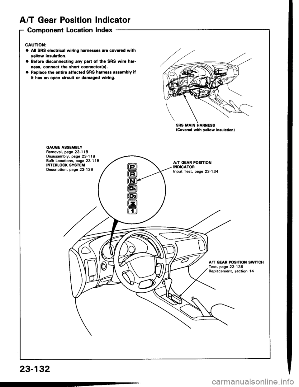
A/T Gear PositionIndicator
Component Locationlndex
23-132
cAUTtOt{:
a All SRS olectdcal wiring harnossos a16 covarod with
yellow insulation.
Boforo disconnocting any part ot the SRS wlr. har-
noaa, conngct the short conn6ctor(sl.
Roplaco tho entire aff6ct6d SRS harn$s assombly il
it has an op6n cilcuit or damagod wiling,
SRS MAIN HARI{ESS(Cov.rod whh ygllow io.ul.tlonl
GAUGE ASSEMBLYBemoval, page 23-1 18Disassombly, pag€ 23'1 19Bulb Locations, pago 23-1 15IiIIERLOCK SYSTEMDGscription. page 23-139
A/T GEAR POSITIONIlTDICATORInput Test, pago 23-134
A/T GEAR P('SITIOI{ SWITCHTest, page 23-136ReDlacement, 6ection 14
Page 1240 of 1413
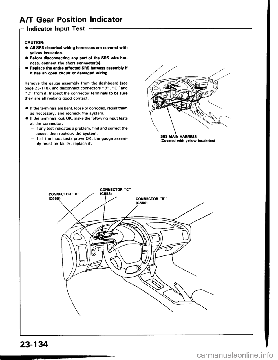
A/T Gear Position Indicator
Indicator Input Test
CAUTION:
a All SRS electrical widng harn6ssos ara cov6r6d whh
yellow insulation.
a Before disconnecting any part ot the SRS wiro hEr-
ness. connect the shon connoctolls).
a Replace the entire affectod SRS harnosr assombly il
it has an op€n circuit or damaged wiring.
Remove the gauge assembly from the dashboard (see
page 23- l 1 8), and disconnect connectors "8", "C" and"D" from it. lnsoect the connecto. terminals to be sure
they are all making good contact.
a lf the terminals are bent. loose or corroded, repair them
as necessary, and recheck the system.
a lf the terminals look OK, make the following input tests
at the connector.- lf any test indicates a problem, find and corect the
cause, then recheck the system.- lf all the input tests prove OK, the gauge assem-
bly must be taulty; replace it.
CONI{ECTOR "8"
SS
23-134