harness HONDA INTEGRA 1994 4.G Manual Online
[x] Cancel search | Manufacturer: HONDA, Model Year: 1994, Model line: INTEGRA, Model: HONDA INTEGRA 1994 4.GPages: 1413, PDF Size: 37.94 MB
Page 1000 of 1413
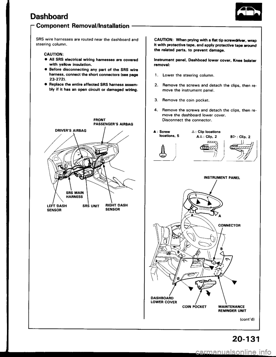
Dashboard
Component Removal/lnstallation
SRS wire harnesses are routed near the dashboard andsteering column.
CAUTION:
a All SRS olectrical wiring harnesses ar6 covolodwith yallow insulation.
a Betoro disconnecting any paft ot th6 SRS wiro
harn€ss, connoct th€ shoi connectots (s66 page
23-2721.
a Replaco th€ entire Itlocted SRS hsrness asaem-
bly il h has an open circuh or damagod wiring.
CAUTION: Whan prying with a flat tip scrowdiv... wrapit with protoctiv€ tape, and apply protectivo tapo a.oundth€ felatsd parts. to provent damag€.
Instiumont p8n6l, Dashboad lower covor. Knec bobtcframoval:
l. Lower the steering column.
2. Remove the screws and detach the cliDs, then re-
move the instrument panel.
3. Remove the coin oocket.
4. Remove the screws and detach the clips, then re-
move the dashboard lower cover.
Disconnect the connector.
: Scrawlocation3, 5
AIF|]A\g)
A i Clip locationg
AA: Cllp, 2 B> : Clip, 2
I l-l L'l| ,-__-, )
itrvi
) 4Z)
_:n,,4<-ft
INSTRUMENT PAI{EL
(cont'd)
COIN POCKET
20-131
Page 1002 of 1413
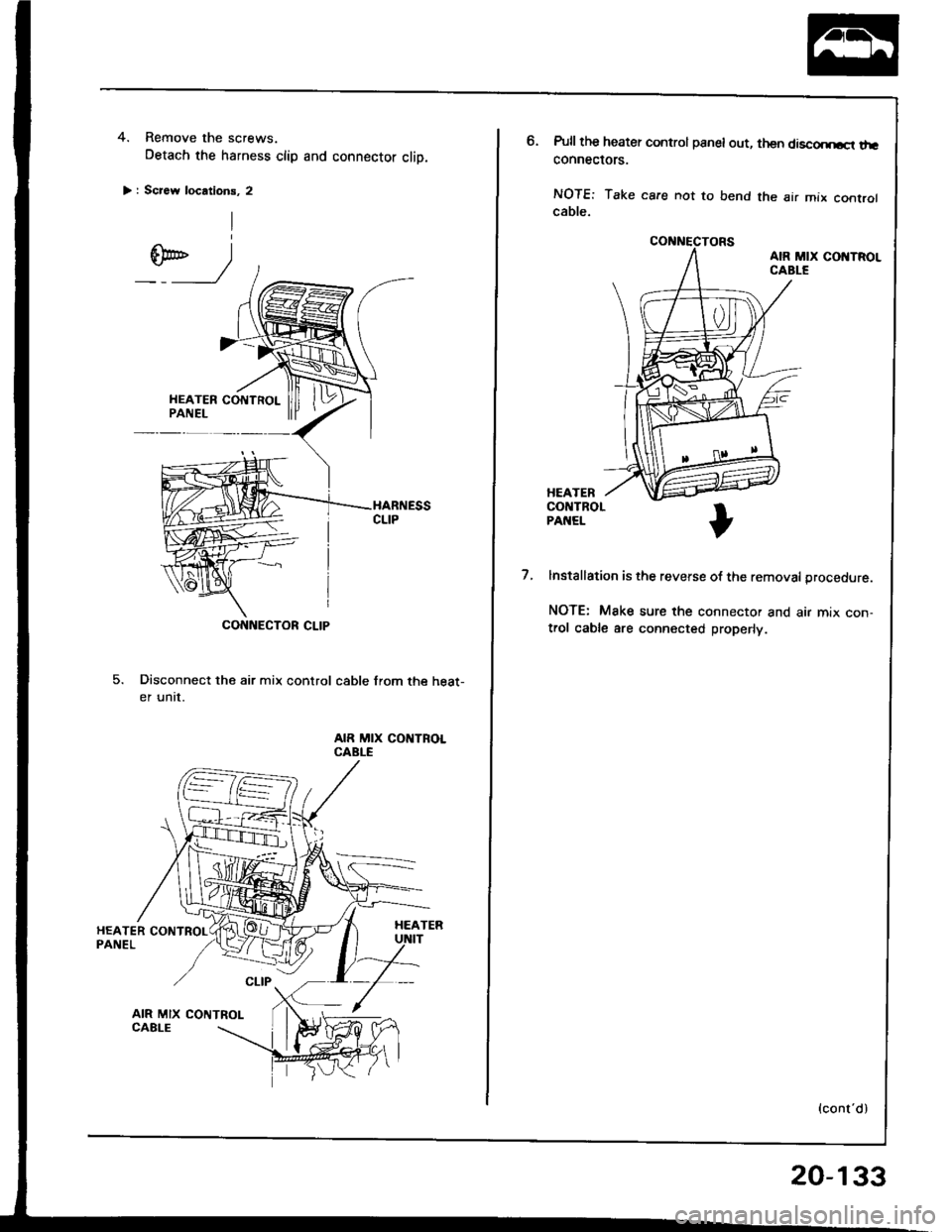
4. Remove the screws.
Detach the harness clip and connector clip.
> : Screw locations, 2
Disconnect the air mix control cable from the heat-
er unrt.
AIR MIX CONTROLCABLE
AIR MIX CONTROL
CONNECTOR CLIP
HEATER CONTROL
CABLE
20-133
Pull the heater control panel out, then disco.rEt rhGconneclors.
NOTE: Take care not to bend the atr mtx controlcable.
AIR MIX COI{TROLCABLE
HEATERCONTROIPANEL
7, lnstallation is the reverse o{ the removal procedure.
NOTE: Make sure the connector and air mix con-trol cable are connected properly.
(cont'd)
Page 1005 of 1413
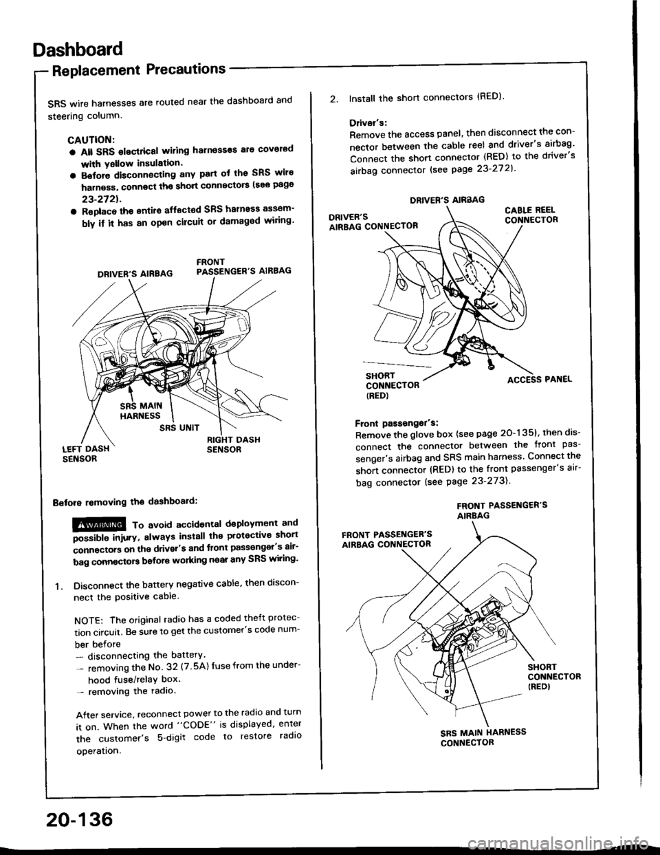
Dashboard
Replacement Precautions
SRS wife harnesses are routed near the dashboard and
steering column.
CAUTION:
a Alt SRS olectrical wiling harness€s ale covorad
with Yollow insulation.
a Botore disconnecting any part ot the SRS wiro
harness, connect ths short connscto6 (see page
23-2721.
a Roplac6 ih€ entiro aflectod SRS halnoss assem-
bly il it has an opon cilcuit or damagod wiling'
LEFT DASHSENSOR
Bstora lomoving the dashboaid:
!@@ To avord accioenlal dsployment and
""iUU inir.v, always install the plotoctive short
;onnectors on the driver's and tlont pass€ngel's air-
bag connectors bolors working near any SRS wiring'
1. Disconnect the battery negative cable, then discon-
necl the positive cable.
NOTE: The original radio has a coded theft protec
tion circuit. Be sure to get the customer's code num-
ber before- disconnecting the battery.
- removing the No 32 (7.5A) Iuse from the under-
hood fuse/relaY box'- removing the radio.
After service, reconnect power to the radio and turn
it on. When the word "CODE" is displayed, enter
the customer's 5 digit code to restore radlo
ooeration.
DRIVER'S AIREAG
SRS UNIT
20-136
DRIVER'S AIRBAG
2.lnstall the short connectors (RED)
Ddvar's:
Remove the access panel, then disconnect the con-
nector between the cable reel and driver's airbag'
Connect the short connector (RED) to the driver's
airbag connector lsee page 23-27 2l'
DRIVER'SAIRBAG CONNECTOB
CABLE REELCONNECTOR
SHORTCONNECTOR(RED)
Front passongor's:
Remove the glove box {see page 20-135}, then dis-
connect the connector between the tront pas'
senger's airbag and SRS main harness Connect the
short connector (RED) to the front passenger's air-
bag connector (see Page 23-273).
FROf{T PASSENGER'SAIRBAG
ACCESS PAI{EL
FRONT PASSET{GER'SAIRBAG CONNECTON
SHORTCONNECTOR(REDI
SBS MAIN HARNESS
CONNECTOR
Page 1006 of 1413
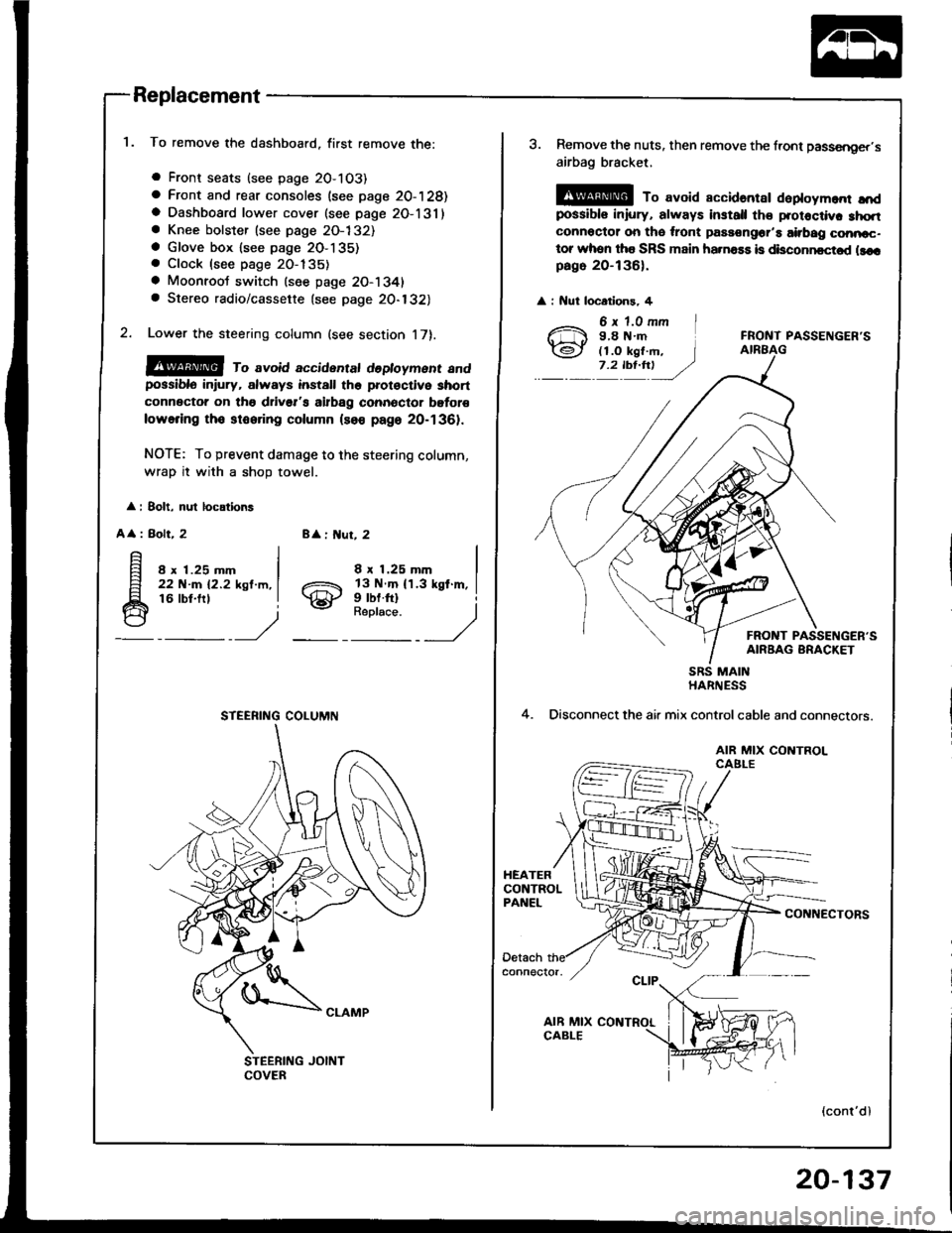
Replacement
To remove the dashboard, first remove the:
a Front seats (see page 2O-103)
a Front and rear consoles (see page 20-128)a Dashboard lower cover (see page 2O-131)a Knee bolster (see page 2O-132)a Glove box lsee page 2O-135). Clock (see page 20-135)
a Moonroot switch (see page 20-1341a Stereo radio/cassette {see page 20-132)
Lower the steering column (see section 17).
@@ ro avoid accidentat dedoyment andpossiblo in ury, always install the prot€ctive short
connector on tho drivsr's airbag connector bgtor€
lowering tho stooring column (so€ page 20-1361.
NOTE: To prevent damage to the steering column,
wrap it with a shoD towel.
: 8olt, nul locations
A
: Bolt, 28 : ut, 2
8 x 1.25 mm22 N-m 12.2 ksl.m,16 lbt.frl
8 x 1.25 mm
gill$"'l
STEERING COLUMN
3. Remove the nuts, then remove the front passsnger,s
airbag bracket,
@ To avoid accidantar daploym.nr ",'dpossibls iniury, always install th€ protoctiv. 3hqtconnoctor on tho ,ront passongor'a airbag conncc-tor whon tha SRS main ha.na$ is disconncctod llcrpago 20-136).
: Nut locatlons, 4
FRONT PASSENGER'S
FRONT PASSENGER'SAIRBAG BRACKET
4.
SRS MAINHARNESS
Disconnect the air mix controlcable and connectors.
AIR MIX CONTROLCAELE
CONNECTORS
(cont'dl
20-137
Page 1007 of 1413
Dashboard
Replacement (cont'd)
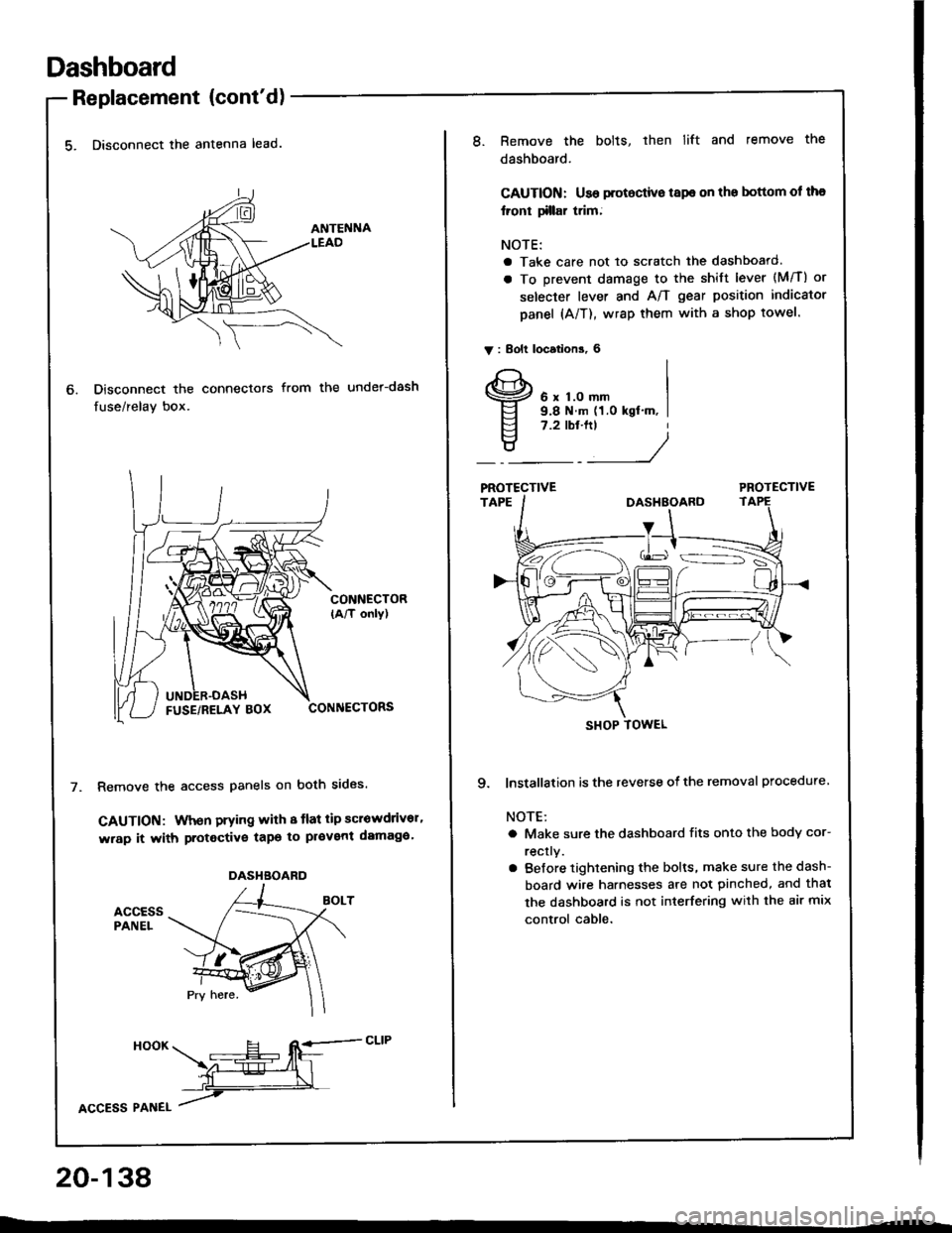
5. Disconnect the antenna lead.
Disconnect the connectors
fuse/relay box.
from the under-dash
CONNECTOR(A/T only)
CONNECTORS
Remove the access panels on both sides.
GAUTION: When prying with 8 tlat tip scrowdrivor'
wrap it with protective tapo to pl€vent damaga'
accEssPANEL
6.
DASHBOARD
HooK ___E-- RE=-cLrP
ffiL
lcCesS Plnel /
20-138
8.Remove the bolts, then lift and remove the
dashboard.
CAUTION: Use protoctive tspe on the bottom ol tha
lront tillar trim;
NOTE:
a Take care not to scratch the dashboard.
a To prevent damage to the shift lever (M/T) or
selecter lever and A/T gear position indicator
panel (A/T), wrap them with a shop towel.
V : Bolt locations, 6
6 x 1.0 mm9.8 N.m (1.0 kgt'm, I7.2 tbt.ftt
____/
PROTECTIVE
9. lnstallation is the reverse of the removal procedure
NOTE:
a Make sure the dashboard fits onto the body cor-
rectly.
a Before tightening the bolts, make sure the dash-
board wire harnesses are not pinched, and thal
the dashboard is not interfering with the air mix
control cable.
SHOP TOWEL
Page 1010 of 1413
Rear Bumper Replacement
NOTE:
a An assjstant is helpful when femoving the rear bum-per and rear bumper beam.
a Take care not to scratch the rear bumper.
Hatchback
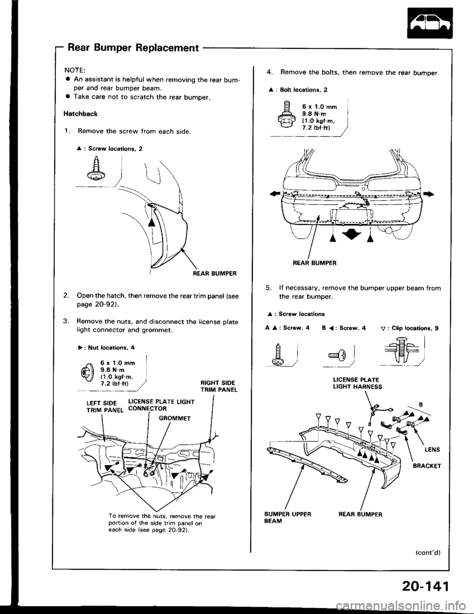
1. Remove the screw from each side.
REAR BUMPER
Open the hatch, then remove the rear trim panel (see
page 20-921-
Remove the nuts, and disconnect the license plate
light connector and grommet.
Scrow I
A
A\
:
J.
> : Nut locotions, 4
/ 6x1.Omm I
Q) i;L'i$-. l
_':'y:) ,/BIGHT SIDETRIM PANEL
To remove the nuts, remove the rearportion of the side trim panel oneach slde {see page 20-921.
LEFT S|DE L|CENSE PLATE LtcHT
4. Remove the bolts, then remove the rear bumper.
: Bolt locations, 2
5. lf necessary, remove the bumper upper beam from
the rear bumper.
: Screw locotions
A : Scr€w, 4 B <: Sc.ow, 4 V: Clip locations, I
REAR BUMPER
--E- I
.--r-Fl^ |--lEr-
_\"., J
^i
@sl
_'/
LICENSE PI-ATELIGHT HARNESS
(cont'd)
REAR BUMPER
20-141
Page 1012 of 1413
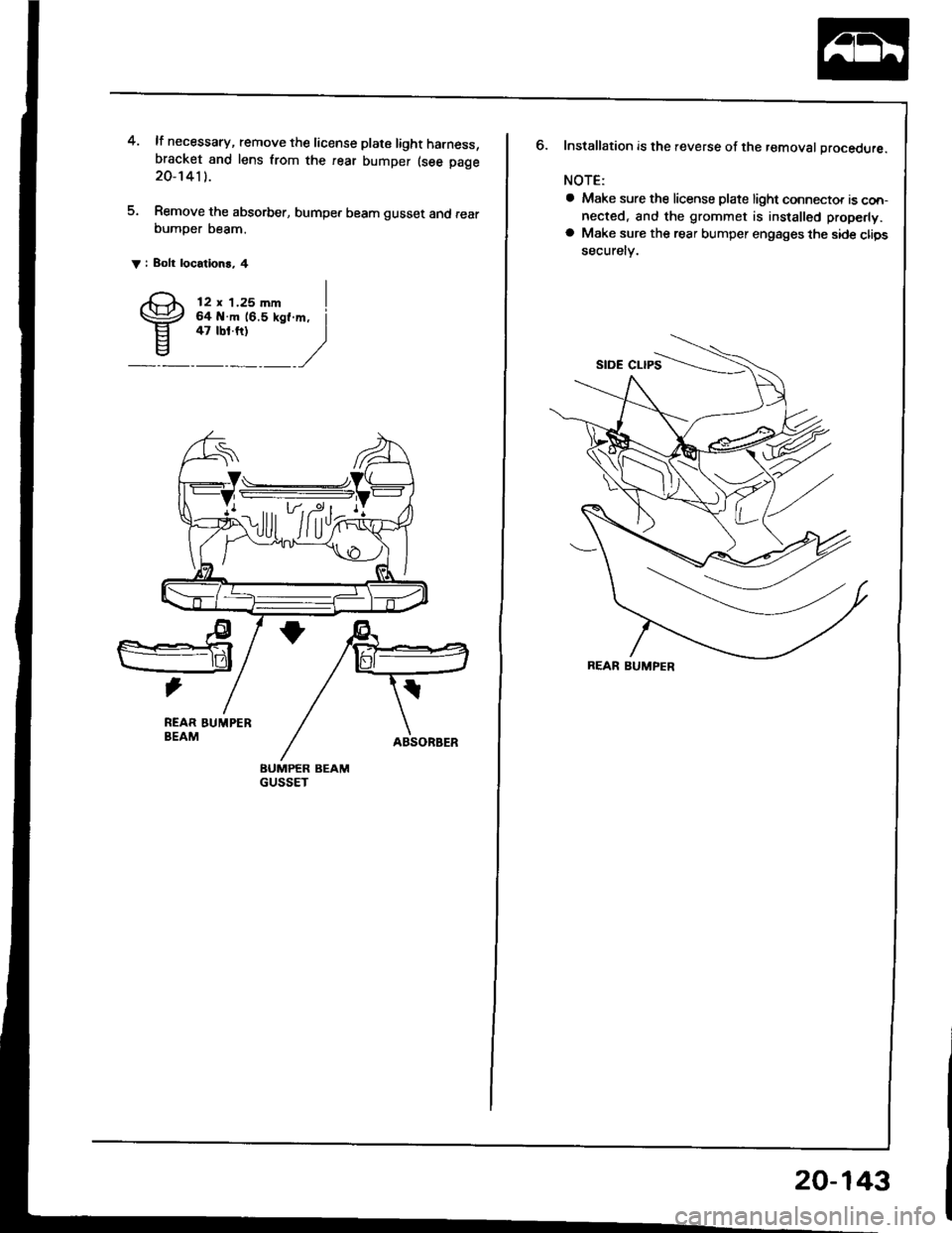
4. lf necessary, remove the license plate light harness,bracket and lens from the rear bumper (see page20-1411.
5. Remove the absorb€r, bumper beam gusset and fearbumper beam.
V i Bolt locatlons, 4
REAR BUMPERBEAM
BUMPER BEAMGUSSET
12 x 1.25 mm64 .m (6.5 kgf47 tbt.ftl
I.m, j
)
6. Installation is the .everse of the removal procedure.
NOTE:
a Make sure the license plate light connector is con-
nected, and the grommet is installed properly.
a Make sure the rear bumper engages the side clips
securelv.
REAR BUMPER
20-143
Page 1015 of 1413
Hatch
Replacement
NOTE:
a An assistant is helpful when removing the hatch.
a Take care not to damage the hatch and body.
a Take care not to scratch the hatch side trims and hatch
tnm paner.
a Open the hatch.
a Remove the high mount brake light {see section 23).
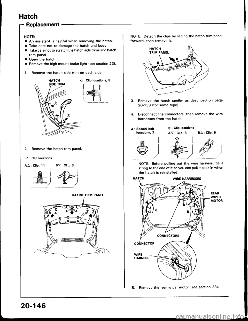
1. Remove the hatch side trim on each side.
HATCH< : Clip locations, 8
2. Remove the hatch trim panel.
A : Clip localions
AA : Clip, 11 BV : Clip, 3
W', dtri
::::/ _:_/
HATCH TRIM PANEL
NOTE: Detach the clips by sliding the hatch trim panel
forward, then remove it.
3. Remove the hatch spoiler as described on page
20-159 (for some type).
4. Disconnect the connectors, then remove the wire
harnesses from the hatch.
: Speclal boltlocetlons,2
V : Clip locations
Av : Clip, 3 BA: CliP, 6
4
t+Ltfrl
l'R@t
,/ L,/
A
@
l
)
NOTE: Before pulling out the wire harness, tre a
strinq to the end of it so you can pull it back in when
the hatch is reinstalled.
HATCI{WIRE I{ARNESSES
CONNECTORS
CONNECTOR
WIREHARNESS
20-146
5. Remove the rear wiper motor (see section 23).
Page 1018 of 1413
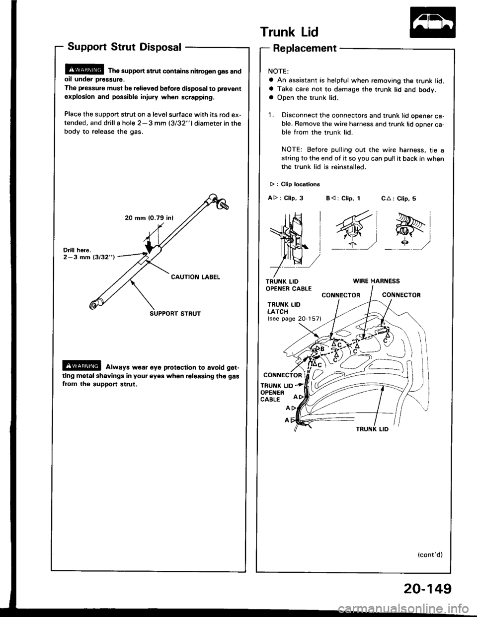
20 mm (O.79 inl
SUPPORT STRUT
Support Strut Disposal
@ Tha support strut contains nitrog.n gas andoil unde. pr€ssul€.
The pressure must be relieved bsfo.e disposal to prevant
explosion and possible injury wh€n sc.apping.
Place the support strut on a level surface with its rod ex-
tended, and drilla hole 2-3 mm (3/32"1diameter in the
body to release the gas.
@ always w€ar €ye prot6ction to avoid get-
ting motal shavings in your eyea when roloasing th€ gas
fiom the support st.ut.
Trunk Lid
TRUNK LIDOPEN€R CABLE
TRUNK LIDLATCH{see page 20-157}
TRUNK LIOOPENERCABLE
CA : Clip, 5
e-i
_rP ,/
Replacement
NOTE:
a An assistant is helpful when removing the trunk lid.a Take care not to damage the t.unk lid and body.a Open the trunk lid.
1. Disconnect the connectors and trunk lid opener ca-ble. Remove the wire harness and t.unk lid opner ca-ble from the trunk lid.
NOTE: Before pulling out the wire harness, tie astring to the end ot it so you can pull it back in when
the trunk lid is reinstalled.
> : Clip locationg
AD : Clip, 3 B< : Clip, 1
WIRE HARNESS
CONNECTORCONIIECTOR
A
A
(cont'd)
20-149
Page 1039 of 1413
lllustrated Index
CAUTION:
a All SRS electrical wiling harnesses are covered with
y€llow insulation.
a Bafore disconnecting any pan of the SRS wile har-
ness. connect the sholt connectorlsl.
a Replace the sntire aflected SRS halness assembly if
it has an open circuit or damaged wiring.
NOTE: The original radio has a coded thelt protection
circuit. Be sure to get the customer's code number before- disconnecting the battery.- removing the No. 32 (7.5 Al fuse lrom the under-
hood fuse/relav box.- removing the radio.
After service, reconnect power to the radio and turn it
on. when the word "CODE" is displayed, enter the cus-
tomer's 5-digit code to restore radio operation.
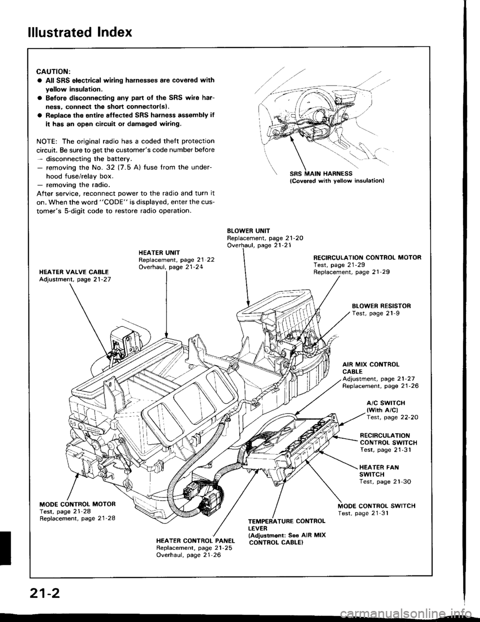
BLOWER UNITReplacement, page 21-2OOverhaul, page 21-21HEATER UNITRepfacement, page 2l 22Overhaul, page 21-24
RECIRCULATION CONTROL MOTORTest, page 21-29Replacement, page 21 29I{EATER VAIVE CABLEAdjustment, page 21-27
BLOWEN RESISTORTest, page 21-9
AIR MIX CONTROLCABLEAd,ustment, page 21-27Replacement. page 21-26
a/c swrTcH(wirh A/clTest, page 22-20
RECIRCULATIONCONTROL SWITCHTest, page 21-31
HEATER FANswtTcHTest, page 2'l-3O
MODE CONTROL MOTORTest, page 21-28Repfacement, page 21'28
MODE CONTROL SWITCHTest, page 21'31
HEATER CONTROL PANELRepf acement, page 21 -25
Overhaul, page 21-26
TEMPERATURE CONTROLLEVER(Adjustmonl: See AIR MIXCONTROL CABLE}
SRS MAIN HARNESS
W,
21-2
I