relay HONDA INTEGRA 1994 4.G Manual Online
[x] Cancel search | Manufacturer: HONDA, Model Year: 1994, Model line: INTEGRA, Model: HONDA INTEGRA 1994 4.GPages: 1413, PDF Size: 37.94 MB
Page 1161 of 1413
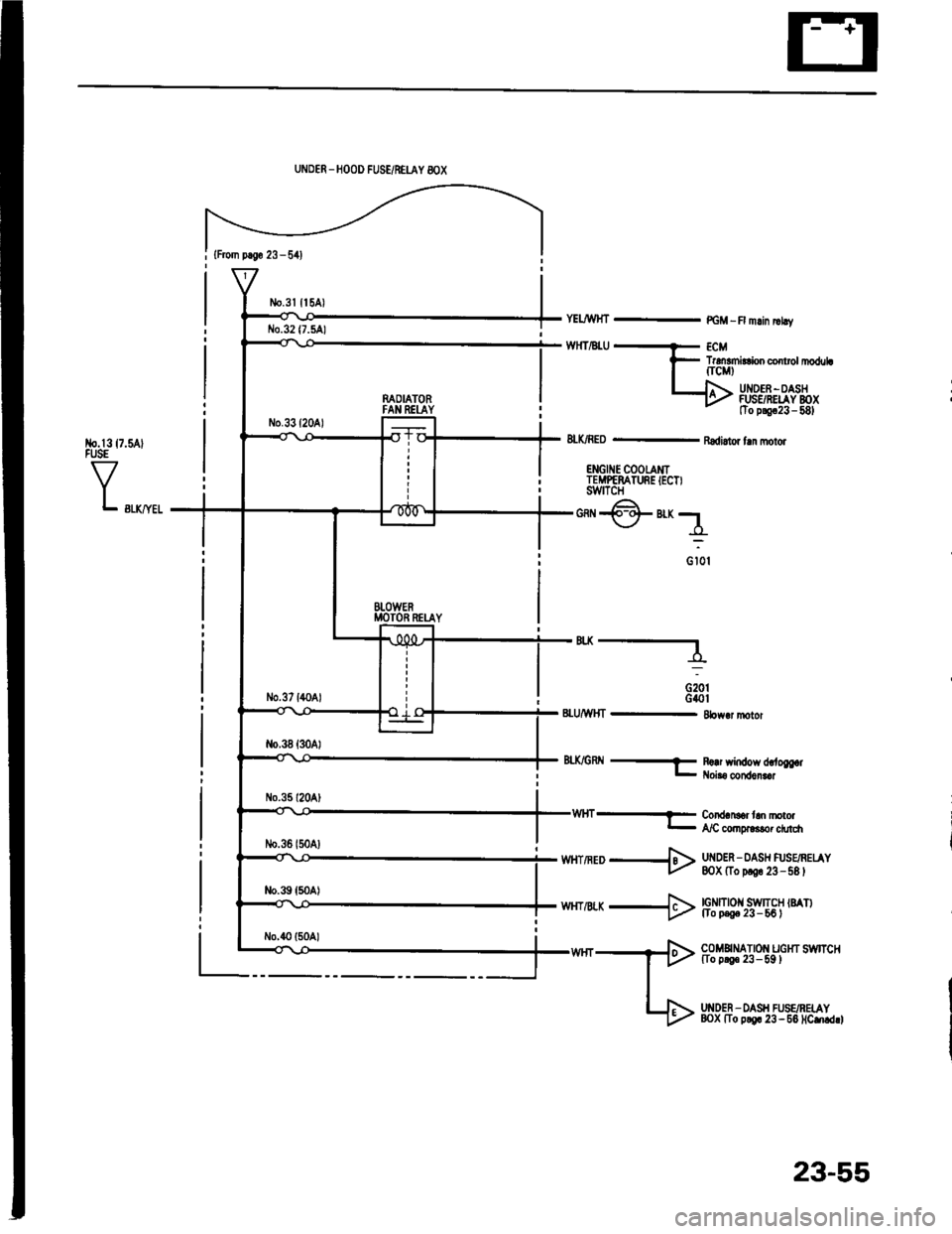
{From p.So 23 - 541
No.l317.5AlFUSE
VL swyel
UNDER _HOOD FUSE/NEUY 8OX
n^OIATORFAN REI-AY
BTOWERMOTOR RETAY
YELJWHT - PGM -R mlin |rhv
TrdEmirConco rolrl|oduLfrcMt
UI{DEF -OASHFUSSRELAY BOXtTo p!9c23 - 581
8LK/RED - Radi.tor fln molor
ENGII{E COOTAMITEMPEMTURE IECT)swtTcH
*@"r;1
o iot
'"----
G20tG40t8LU/WHT - 8bw.r motor
8tX/GRtl -f R!!r window d,.to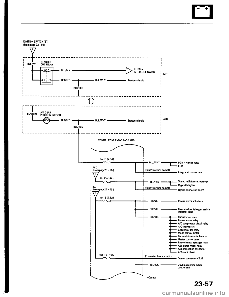
IGNITION SWTCH ISTIlFrom p.!€ 23 - 561
f7
I.---F-------lI-lSTARTFPi Bffi,!'HT 6u?'ili,iY i| -' r r l clurcr It-11iPt ;rui8rr H inl-rhicicxswrcr 1,,,,,,Itill-+{ .'.i o-F BIK/RED --.5 BLX/!\,HT - st.der sotenoid il-l I r
BLK/REO
fr
r---
uxrivn Sr$!gfr*,r.,
L€-eumoBLKMHT - Starlsr solenoki
-------J
UNDER -DASH FUSEiRELAY BOX
No.l817.5A)ELUMHT --?- PGM _ Ft msin rctay- ECM
lnt€gretod control unit
St6r6o radio/c$r€tt6 playot
Cig€rone lightor
Option connoctor: C927
Pow6r minor *tuetols
noar wandow dologgor switchindicrtor light
R6dietor fan robyElowor motor rclayfuC compr$sor clutch rsl6yA/C lhomGtstCond6ns& tan ml6yMod6 control motorRocicubtion control motorH6at€r control panolRear window deloggor relayABS pomp motor tolayABS insp€ction connoctorABS contrcl unit
Option connoctor:C925
Daytime running lightscontrolunit
(From pag623-56 )
No.23ll5AlYEURED --E
lG2lFrom p.!623- 56 ){Fus€/relay box sockotl
+ l,lo,16 {7.5A1
23-57
Page 1165 of 1413
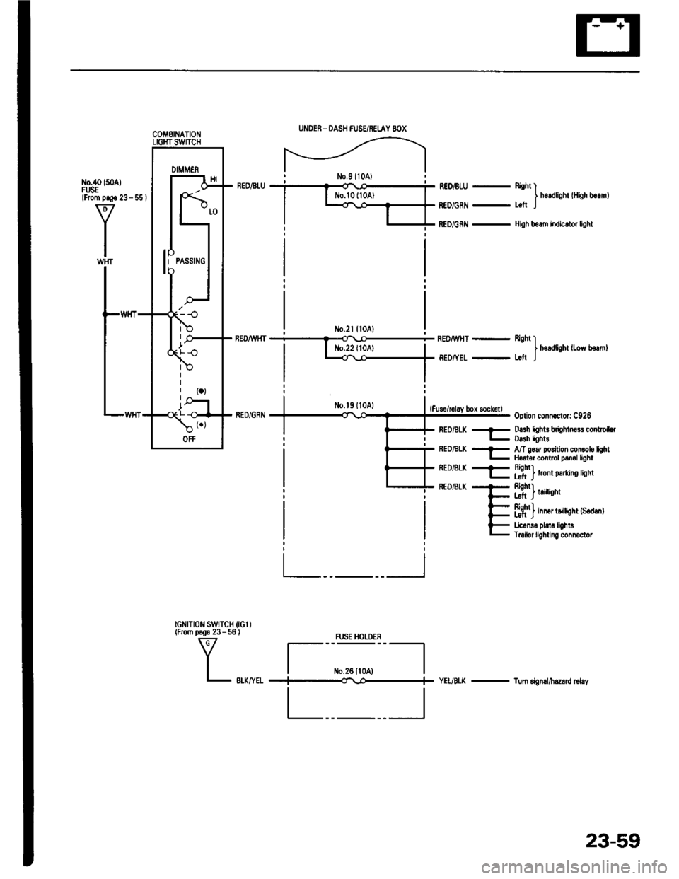
UNOER - DASH FUSE/RELAY 8OX
DIMMENNo.9l10A)neontu i ? o *c--i- REo/BLU - ftght l| | No.lolloAl I I hordlishr lHish b.rml
|
--E:::::l-
l"JnJ"",,**".,,,*
No.2l ll0A)REDiU,HT+REo^wHT _ Rgh, II I No.22 ll0Al | | h.rdlioht lLow b€rml
| -TiED,TEL-L.trr
tl
option condsclor: C926
RED/BLK * o.sh hhts briohtners co .oll€rL Dlsh lght!REDALK ..- A/T gorr pGition conloh hht- Horler control Drnel liohtREDEL( + Rishn .l_tft Iro parung rgnr
tGNtTloN swtTcH ltcl)lFrom p3€6 23 - 56 )
V
Il- BLK,ryELYEUBTK - Tum dgnd/hazrrd r6i.y
fff')t.'..,nt
f#t) inner tillisht {s€danl
Lic.n!€ pbt€ li0htsTruilor liglfi ng connoclor
FUS€ HOLDER
tlI m.ze rroo I
#
tltlI____-l
23-59
Page 1172 of 1413
Battery
a Battory tluid (6lectrolyt€l contains sulturic acid. lt may cauaa aevere burns iI it gots on your skin or in youl oyos.
Woar protoctivo clothing and I fac€ shield,- ll aloctrolyt6 gots on youl skin or clothos, rimo it off with wator immediately,- lf eloclrolyto g6ts in your oyos, tlush it out by splashing wat6r in youl eyes for at least 15 minutes; call a physiclan
immediately,
a A battery gives off hydrogon gas, lf ignit6d. tha hydrogsn will orploda and could crack tho baflory cas6 and splattor
acid on you. Koep spa*s. flames, and cigarottos away from the baftery.
a Overcharging will raiso ths tempelature ot th€ electrolyte. This may force electrolyte to splay out of the battery venta.
Follow lhe chargor manutacturer's instluctions and chargo tho battory at a prop61 rate.
NOTE: The original radio has a coded theft protection circuit. lt service to the car requires any of the lollowing, be sure
to get the customer's code number before- disconnecting the battery.- removing No. 32 (7.5 Al fuse from the under-hood fuse/relay box- removing the radio,
After service, reconnect power to the radio and turn it on. When the word "CODE" is displayed, enter the customer's
s-digir code to restore radio operation,
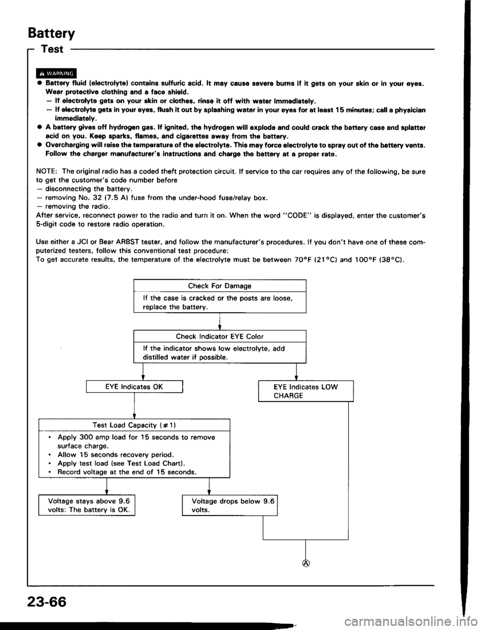
Use either a JCI or Bear ARBST tester, and follow the manufacturer's procedures. It you don'r have one of these com-puterized testers, follow this conventional test procedure:
To get accurate results, the temperature ot the electrolyte must be between TOoF l21ool and IOOoF {38oCl.
lf the case is cracked or the posts are loose,
replace the battery.
lf the indicator shows low electrolvte, add
distilled water it oossible.
Test Load Cspacity (# 1)
. Apply 3OO amp losd fo. 15 seconds to remove
surJace charge.. Allow 15 seconds recovery period.. Apply test load (see Test Load Chartl.. Record voltage at the end of 15 seconds.
Voltage stays above 9.6
volts: The batterv is OK.
23-66
Page 1174 of 1413
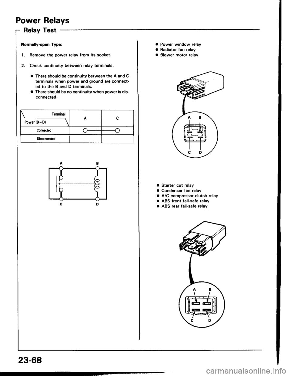
Power Relays
Relay Test
t{ormally-op€n Type:
1. Remove the power relay from its sockat.
2. Check continuity between relay terminals.
a There should be continuity between the A and C
terminals when power and ground ar€ connect-
ed to the B and D t€rminals
a There should be no continuitv wh€n power is dis-
connected.
T6rminal
PowEr (B- D)A
Connactod
Di!c!nnact6d
IP
I
I
tb
23-68
a Power window relay
a Radiator fan relay
a glower motor relav
a Staner cut relay
a Condenser fan .elay
a A/C compressor clutch relay
a ABS t.ont {ail-safe relay
a ABS lear fail-sate relav
.AB
\/
tffit
t[fT4r
\C D,
Page 1177 of 1413
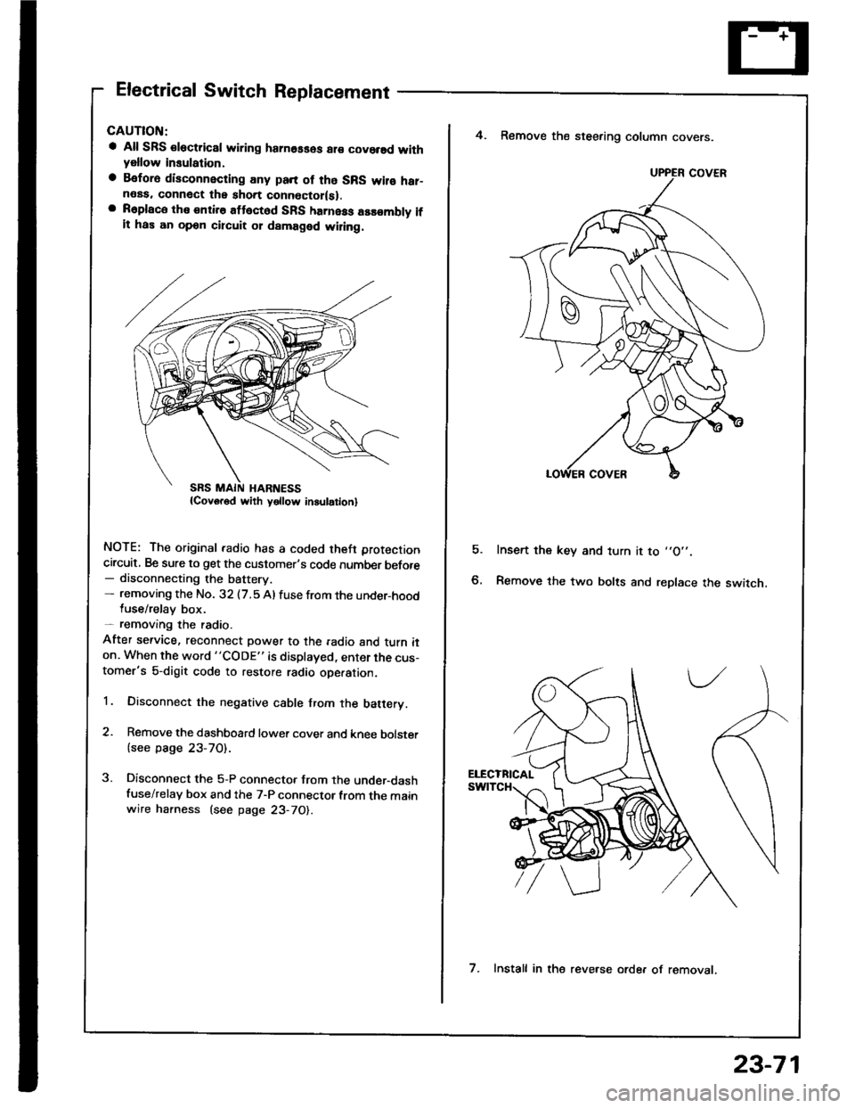
Electrical Switch Replacement
a All SRS €lectric8l wiring hamosses ar€ covorsd withyellow insulation,
a Befora disconnecting any pan of tho SRS wilo har-neas. connect the short connoctor(sl.a R6place the entire attect6d SFS harness assombly ifit has an opon circuit 01 damaged wiling.
NOTE: The original radio has a coded theft protection
circuit, Be sure to get the customer's code number before- disconnecting the battery.- removing the No. 32 (7.5 Al fuse from the under-hoodluse/relay box.- removang the radio.
After service, reconnect power to the radio and turn iton. When the word "CODE" is displayed, enter the cus-tomer's 5-digit code to restore radio ope.ation.
1. Disconnect the negative cable from the batery.
2. Remove the dashboard lower cover and knee bolster
{see page 23-70).
3. Disconnect the 5-P connector from the under-dashfuse/relay box and the 7-P connector from the mainwire harness (see page 23-70).
E
4. Remove the steering column covers.
Insert the key and turn it to ,,O',.
Remove the two bolts and replace the switch.
UPPER COVER
7. Install in the reve.se orde. of removat.
23-71
Page 1178 of 1413
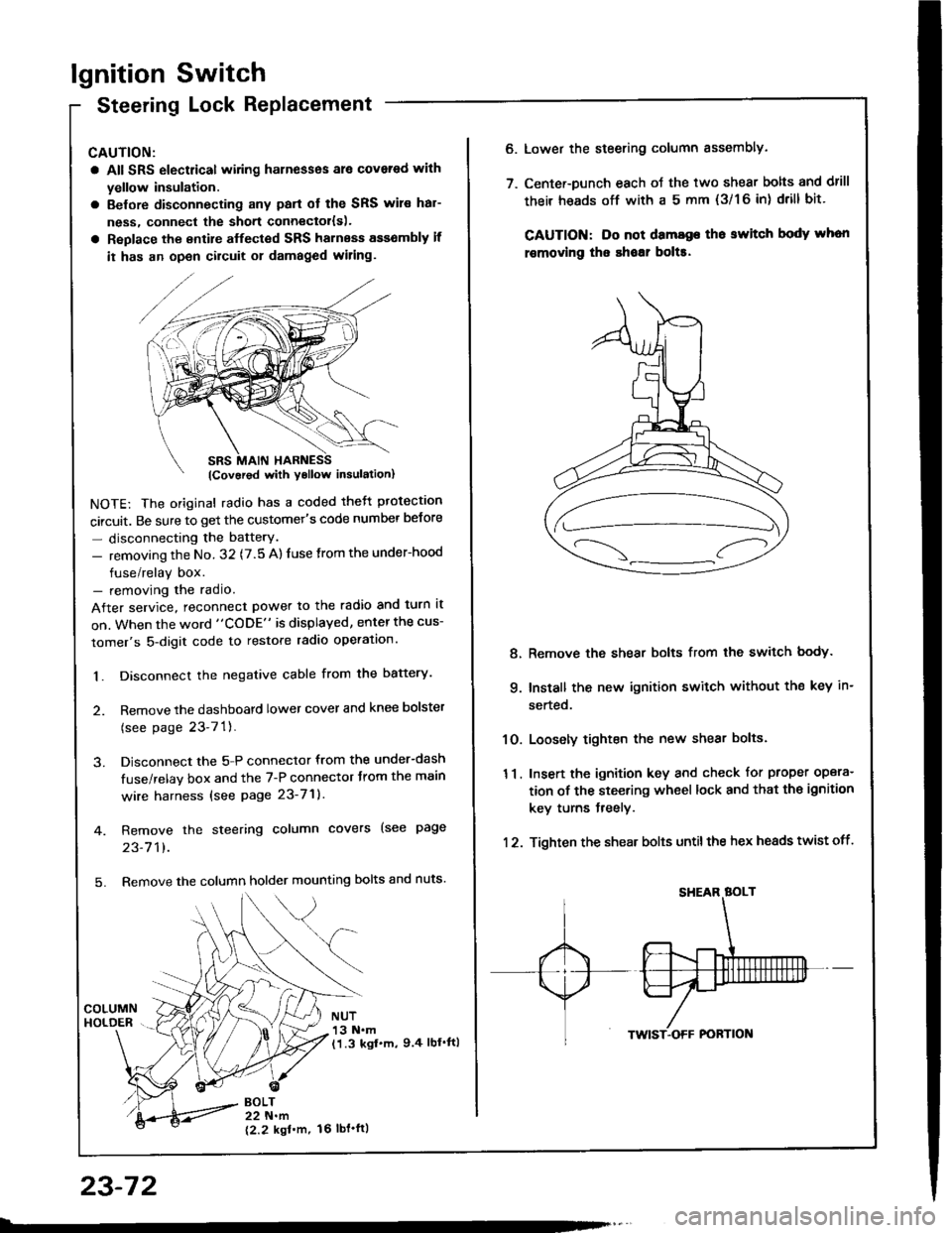
lgnition Switch
Steering Lock Replacement
CAUTION:
a All SRS electrical wiring harnesses ale covsred with
yellow insulation.
a Belore disconnecting any parl ot the SRS wir€ hal-
ness, connecl the short connector{s).
a Replace the entire alfected SRS harness a$6mbly il
it has an open circuit or damaged wiring.
NOTE: The original radio has a coded thett protection
circuit. Be sure to get the customer's code number betore
- disconnecting the batterY.
- removing the No. 32 (7.5 A) fuse from the under-hood
fuse/relay box.- removing the radio.
After service, reconnect power to the radio and turn it
on. When the word "CODE" is displayed, enter the cus-
tomer's 5-digit code to restore radio operation.
1. Disconnect the negative cable from the battery.
2. Remove the dashboald lower cover and knee bolster
(see page 23-7'l ).
3. Disconnect the 5-P connector from the under-dash
fuse/relay box and the 7-P connector trom the main
wire harness {see page 23-71).
4. Remove the steering column covers (see page
23-711.
5. Remove the column holder mounting bolts and nuts'
BOLT22 N.m
12.2 kgl'm.
NUT13 N.m(1.3 kgf.m, 9.4 lbl'ftl
23-72
16 tbt.ftl
6. Lower the steering column sssembly.
7. Center-Dunch each oJ the two shear bolts and drill
their heads off with a 5 mm {3/1 6 in) drill bit'
CAUTION: Do not dama96 tho switch body whon
r€movlng the shoar bol$.
Remove the shear bolts from the switch body.
Install the new ignition switch without the key in-
serted.
Loosely tighten the new shear bolts.
Insert the ignition key and check for proper opera-
tion of the steering wheel lock and that th€ ignition
key turns freely.
Tighten the shear bolts untilthe hex heads twist off.
8.
q
10.
11.
12.
Page 1179 of 1413
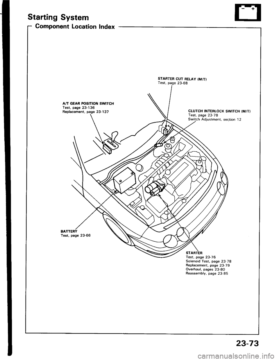
Starting System
Gomponent Location Index
A/T GEAR POSITION SWITCHTest, page 23-136Replacement, page 23-137
BATest, page 23-66
STARTER CUT RELAY {M/T}Test, page 23,68
CLUTCH INTERLOCK SWITCH (M/T}Test, page 23-78Switch Adiustment. section 12
Test, page 23-76Solenoid Test, page 23 78Repfacement, page 23 79Overhaul, pages 23-8OReassembly, page 23,85
23-73
Page 1183 of 1413
5. Check lor 8n op€n in the BLKMHT wire circuit be-
tween the staner and ignition switch, and con-
nectors.
6. Check the ignition switch (see page 23-70).
7, On cars with automatic transmission, check the A/Tgear position switch (neutral position switchl and
connector. On cars with manualtransmission, check
the staner cut relay, clutch interlock switch, and
connectors.
NOTE: Check the No. 39 (5O A) fuse in the under-hood
fuse/relay box for the starter cut relay.
Check tor Woar and Damago:
The starter should crank the engine smoothly and stead-
ily. lf th€ startsr engages, but cranks the engine errati-
cally, remove it. Inspect the starter, drive gear, and
flywheel ring gesr for damage.
a Check the drive gear overunning clutch for binding
or slipping when the armature is rotated with the drivegear held. Replace the gesrs if damaged.
Check Cranking Voltago 8nd Current Draw:
Cranking voltage should be no less than 8.O volts.
Current draw should be no more than 360 amperes.
lf cranking voltag€ is too low, or current draw too high,
check for:
a Fully charged battery
a Open circuit in starter armature commutatot segments
a Starter armature dragging
a Shoned armature winding
a Excessive drag in engine
Chack Cranking rpm:
Engine spsod during cranking should be above 1O0 rpm.
lf spe6d is too low, ch€ck for:
a Loose battsry or starter teminals
a Excessively worn starter brushes
a Open circuit in commutator segments
a Dirty or damaged helical spline or drive gear
a Defective drive gear overrunning clutch
Chock StErtor Disongagomoni:
Press the clutch pedal allth€ way in (M/T), turn the ioni-
tion switch to "lll" and rolease to "11".
The starter drive gear should disengage from the tlywheel
ring gear. When you rolease the key.
lf the drive gear hangs up on th€ flywheel ring gear, check
for:
a Solenoid plunger and switch malfunction
a Dirty drive gear assembly or damaged overrunning
clutch
23-77
Page 1186 of 1413
![HONDA INTEGRA 1994 4.G Manual Online Starting
Startel
System
Overhaul
from clutch side.
-s@]
MOLYBDENUMDISULFIDE
CAUTION: Disconnecl th€ battery n€gative cable befole
lomoving the startet.
NOTE: The original radio has a coded theft p HONDA INTEGRA 1994 4.G Manual Online Starting
Startel
System
Overhaul
from clutch side.
-s@]
MOLYBDENUMDISULFIDE
CAUTION: Disconnecl th€ battery n€gative cable befole
lomoving the startet.
NOTE: The original radio has a coded theft p](/img/13/6067/w960_6067-1185.png)
Starting
Startel
System
Overhaul
from clutch side.
-s@]
MOLYBDENUMDISULFIDE
CAUTION: Disconnecl th€ battery n€gative cable befole
lomoving the startet.
NOTE: The original radio has a coded theft protection
citcuit. Be sure to get the customer's code number before
- disconnecting the batterY.- removing the No.3 2 (7.5 A) fuse from the under-hood
fuse/relay box.- removing the tadio.
Atter service, reconnect power to the radio and turn at
on. When the word "CODE" is displayed, enter the cus-
tomer's 5-digit code to restore radio operation.
tr./.' BRUSH HOLDERTest, page 23-8'l
ERUSH
COVER
I
6
OVERRUNNING CLUTCH ASSEMBLYInspection, page 23_84
SOLENOIDPLUNGERInspection, page 23-85
BRUSH HOLOER
ARMATURE
STARTERSOLENOIDTest, page 23-78
PINION GEAR IDLER GEAR
Inspection, page 23-11
IDLER GEAR
I
@*
SOLENOID HOUSING
HARNESS BRACKET
STEEL BALL
install steel ball
lnspection and Test,page 23-82
ROLLER BEARINGSand CAGEPrevenl rollers trom being scattered and lost.
MOLYBDENUM DISULFIDE
_R1
MOLYADENUMDISULFIDE
23-80
ENO COVER
ARMATURE
GEAR HOUSING