ignition HONDA INTEGRA 1994 4.G Workshop Manual
[x] Cancel search | Manufacturer: HONDA, Model Year: 1994, Model line: INTEGRA, Model: HONDA INTEGRA 1994 4.GPages: 1413, PDF Size: 37.94 MB
Page 97 of 1413
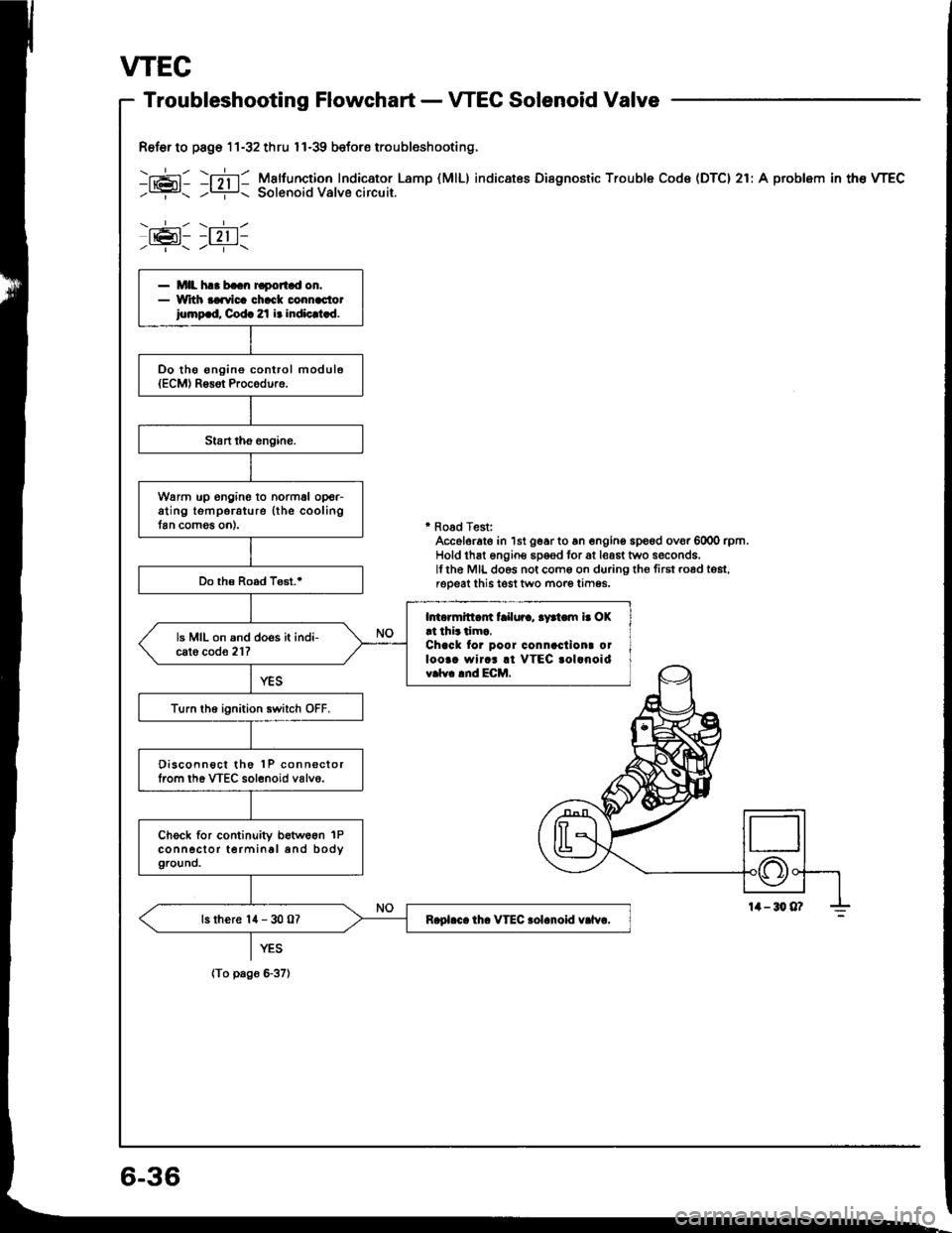
VTEC
Ref€r to page 11-32 thru I l-39 beforo troubleshooting.
-g: -mi !5*3ij'i:,*o:",,XTl.Lamp
(MlL) indicates Disenostic rrouble code (Drc) 2r:A problem in the wEc
\,__-:-/ \.---l-l
Iel- -l 2,1 l-
MIL h.. b..n Fport d on.Wrth aaavica chack connac,tot
iomp.d, Codc 2l i. indic.t.d.
Oo tho ongino control module(ECM) Rg3ot Procgduro.
w6rrn up engine to normal op€r-ating tsmporature (the coolingfan comog on).
Do th€ Road Test.'
lmormitt.m t ilur., .yrtom i. OK!t thi.tim..Chacl tor poor connactiont otloo.. wircr !l VTEC .ol.noidv.lv. lnd ECM.
ls MIL on and does it indi-cato cod€ 21?
Turn tho ignition switch OFF.
Oisconnect tho 1P connsctorlrom the VTEC solenoid valvo.
Chock for continuity betw66n 1Pconn6clor terminal and body
9rcUnO.
ls there '14 - 30 07R.pl.c. th. VTEC rolonoid v.lvr,
' Road Test:Accelerate in 1st gear to 6n engino spood ovor 6000 rpm.Hold thst engine sp€ed tor at least two seconds.lflhe MIL do6s not coms on during th€ first road tost,reoeat this test two more tim95.
YES
(To pago G37l
6-36
Page 99 of 1413
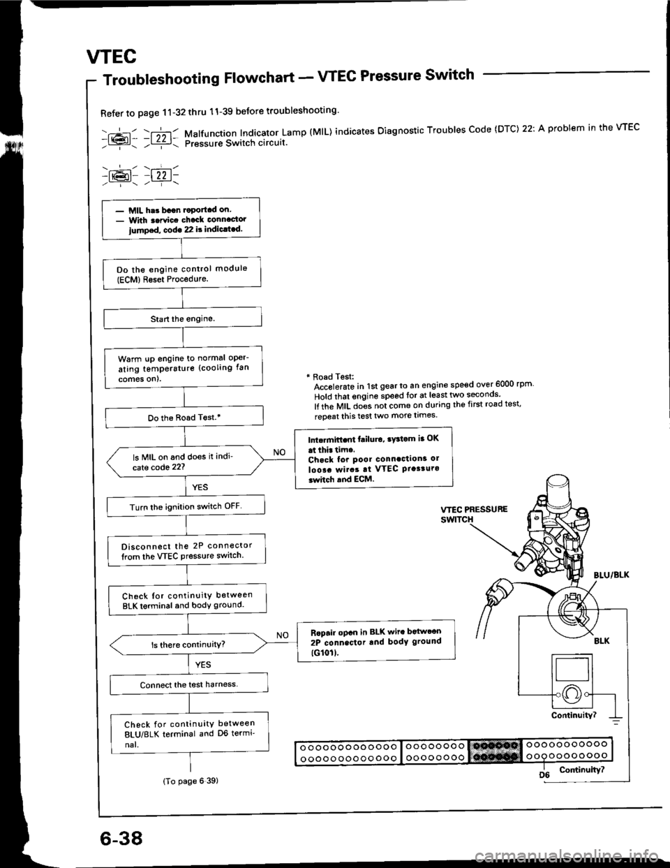
wEc
6-38
Troubleshooting Flowchart - VTEC Pressure Switch
Refer to page 11-32thru 11-39 beJore troubleshooting'
-.+- -r";-r- Malfunction Indicator Lamp (MlL) indicates Oiagnostic Troubles Code (DTC) 22: A problem in the VTEC- l{{?l- ;l ziz r: pressur€ Switch circuit.
-lr@l- |22 1-
* Road Test:Accolerato in lst gear to an engine speed over 6000 rpm
Hold that engine speed for at least two seconos'
lf the MIL does not come on during the first road test'
reoeat this test two more limes.
- MIL har bagn.oportcd on.- With t.rvic. chack connactor
iump.d, cod€ 22 it indic.t.d.
Do the engine control module(ECM)Reset Procedure.
Warm !p engine to normal oper-
ating temperstur€ (cooling fan
comes on).
Do the Boad T€st.'
Intc.mift.nt failu.o, ry3tom ia OK
at thi. tim..Chack for pool connaction3 ol
loo!. rvirat at VTEC Ptasturo3whch and ECM.
ls MIL on and does it indi'
cate code 22?
Turn lhe ignition switch OFF
Disconnect the 2P connector
lrom the VTEC Pressure switch.
Check Ior continuity between
BLK terminal and body ground.
Rcpair opcn in BLK wit. botwcon
2P connector rnd body ground
tG101l.
Check for continuity between
8LU/8LK terminal and D6 termi'
nal.
(To page 6 39)
Page 103 of 1413
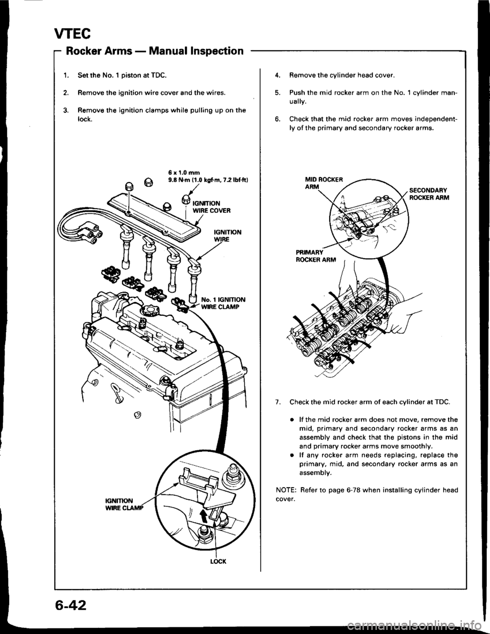
VTEC
Rocker Armsnlrungf rtrrrri' - rYrorrtrcr rrrDPEUtrl,rl
1. Set rh6 No. I Diston at TDC.
2. Remove the ignition wire cover and the wires.
3. Remove the ignition clamps while pulling up on the
lock.
4.Remove the cylinder head cover.
Push the mid rocker arm on the No. 1 cylinder man-
ually.
Check that the mid rocker arm moves independent-
ly of the primary and secondary rocker arms.
6 x 1.0.nm9.8 N.m 11.0 lgfm, 7.2 lbf.ftl
SECONDARYROCKER ARM
7. Check the mid rocker arm of each cvlinder at TDC.
. lf the mid rocker arm does not move, remove the
mid, primary and secondary rocker arms as an
assembly and check that the pistons in the mid
and primary rocker arms move smoothly.
. lf any rocker arm needs replacing, replace the
primary, mid, and secondary rocker arms as an
assemblv.
NOTE: Refer to page 6-78 when installing cylinder head
cover.
w
Page 196 of 1413
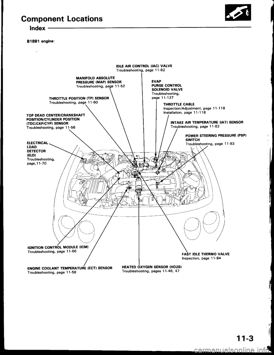
Component Locations
lndex
81881 sngin6:
IOLE AIR CONTROL OACI VALVEpage '11-82T
MANIFOLD ABSOLUTEPRESSURE {MAP} SENSOREVAP
THROTTLE POSITIOIII {TP) SENSORTroubleshooting, page 1 1-60
Troubleshooting,
(ECTI SENSOR HEATEO
PURGE CONTROLSOLENOID VALVETroubleshooting,11-137
THROTTLE CABLEInspection/Adiustment, page 1 1-1 18
Installation, page 11- 1 18
SENSOR lHO2S}
TOP DEAD CENTER/CRATIIKSHAFTPOSITIOf{/CYLINDER POSITION(TDC/CKP/CYP} SENSORTroubleshooting, page 1 1-56
INTAKE AIR TEMP€RATURE IIAT) SEI{SORTroubl€shooting, page 1 1 -62
POWER STEERING PRESSURE (PSP)
swtTcHTroubleshooting. page 11-93
sq
IDLE THERMO VALVEInspection, page 11-94
ELECTRICALLOADOETECTORIELD}Troubleshooting.page,l l-70
IGNITIONMODULE {ICMI
Troubleshooting, page 1 1-66
ENGINE COOLANT TEMPERATroubleshooting, page I 1-58Troubleshooting. pages 11-46, 47
11-3
Page 197 of 1413
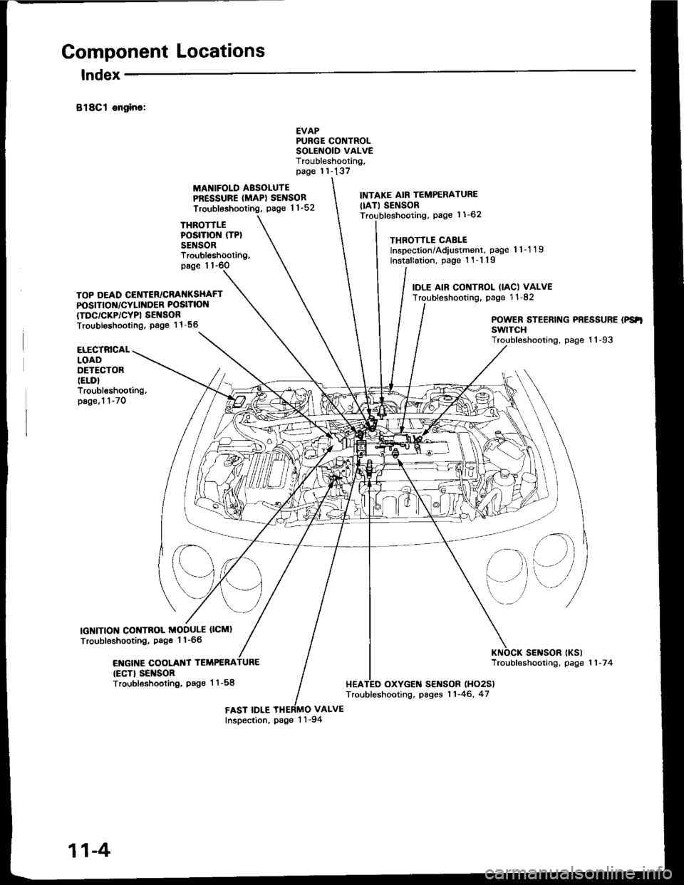
Component Locations
lndex
B18Cl ongino:
THROTTLEPOSITION (TP}
SENSOR
MANIFOLD AESOLUTEPRESSURE (MAPI SENSOR
Troubleshooting, page 1 1-52
EVAPPURGE CONTROLSOLEiIOID VALVETroubleshooting,page 11-137
VALVE
INTAKE AIR TEMPERATURE
IIAT) SENSORpage 11-62
THROTTLE CABLEInspection/Adiustment, page 'l 1-1 19
lnstallation, page 1 1-1 19
IOLE AIF CONTROL (IACI VALVETroubleshooting. page 1 1 -82
Troubleshooting,page 1 1-6O
TOP DEAD CENTER/CRANKSHAFTPOSITION/CYLINDER POSITION
{TDC/CKP/CYPI SEI{SORTroubl€shooting. Page 1 1 -56POWER STEERING PRESSURE (PS'I
swtTcHTroubleshooting, page 1 1-93ELECTRICALLOADDETECTORIELD}Troubleshooting,page.1 1-70
IGNITION CONTNOL MODULE OCMI
Troubleshooting, Psge 1'l-66
ENGIT{E COOLANT TEMPERA
{ECT} SEI{SORTroubleshooting, Pag€ 1 1-58
sElrlsoR tKslTroubfeshooting, page 1 1 -7 4
HEATED OXYGEN SENSOR (HO2S}
Troubleshooting, pages 11-46, 47
FAST IDLEInspection, page 1 'l -94
11-4
Page 224 of 1413
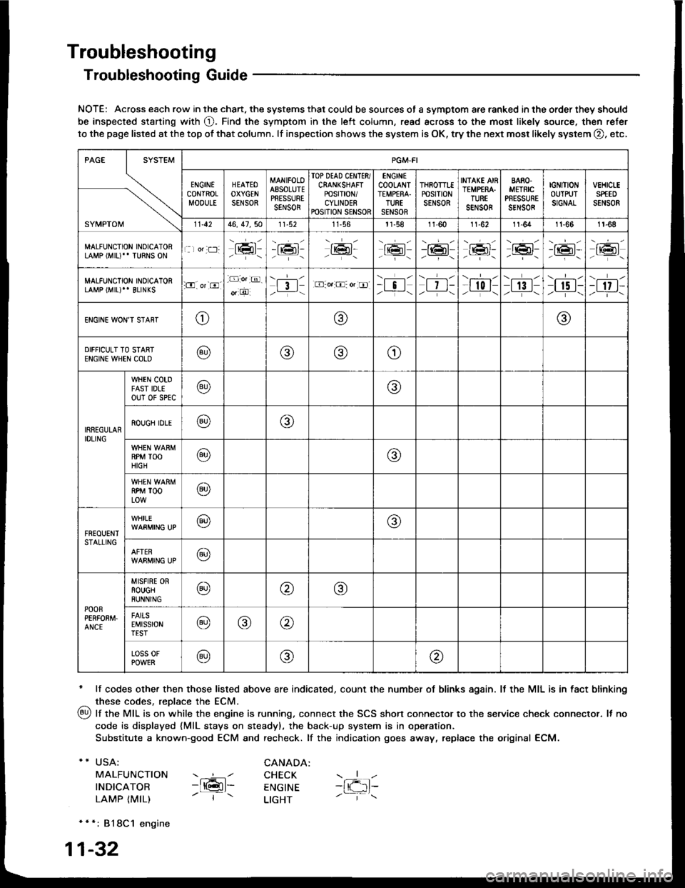
Troubleshooting
Troubleshooting Guide
NOTE: Across each row in the chart. the systems that could be sources of a symptom are ranked in the order they should
be inspected staning with O. Find the symptom in the left column, read across to the most likely source. then refer
to the page listed at the top of that column. lf inspection shows the system is OK, try the next mosr likely system O, etc,
* lf codes other then those listed above are indicated, count the number of blinks again. It the MIL is in fact blinking
^ these codes, replace the ECM.
qy, lf the MIL is on while the engine is running. connect the SCS shon connector to the service check connector. It no
code is displayed {MlL stays on steady), the back-up system is in operation.
Substitute a known-good ECM and recheck. lf the indication goes away, replace the original ECM.
USA:
MALFUNCTION
INDICATOR
LAMP {MIL)
CANADA: ----l CHECK-ltGl- ENGTNE- | - LTGHT
- { -1t-
* * *: 818C1 engine
1-32
SYMPTOM
PGM.FI
ENGINECONTROLMOOULE
HEATEOOXYGENSENSOR
MANIFOLOAESOLUTEPRESSURESENSOR
TOP DEAD CINTTR/CRANKSHAFTPOSTT|ON/CYLINDERPOSITION SENSOR
ENGINECOOLANTTEMPfRA.TURTSENSOR
THROTTTEPOStTtONSENSOR
INfAKE AIRTEMP€RA.TUREsar,rs0R
BARO.METRICPRESSURESENSOR
IGNITIONOUTPUTSIGNAL
vEHtct-ESPfEDSENSOR
11.4246, 47,5011-56l1-581l-6011-6211-641t-661r-68
MALFUNCTION INOICATORLAMP (MIU" TURNS ON1 lor:t:]:lrmr:- i;:i'-tK3t-16l-16l'-\-16l/-----\
-r:+r-
-{"Pr:-o_-16l-.z-\r6t/_-\
MALFUNCTION INOICATORLAMP (MIL)'' BLINKS:O. or-8.-D:o.:@.
o, O'l3l/__-\.E-o.:O: or tr]--i !l/ -i-\| 7 t-/__-\
--l-l-l r0 I/----\| 13 |z_---\
\.--r--l
I r5 t-/.---\-t 17 t-/-]-\
ENGINE WON'T STAffTo@@
DIFFICULT TO STARTENGIN€ WHEN COLO@@(9)o
IRREGULARIDLING
WHEN COTDFAST IDLEouT 0f sPtc@@
ROUGH IDLE@o
RPM TOOHIGH@@
RPM TOOLOW@
FREOUENTSTALLING
WHILE@@
AFTER@
POOnPERFOEM.ANCE
MISFIRE ORROUGHRUNNING@@@
FAITSEMISSIONTEST@@@
Loss 0FPOWER@@@
Page 226 of 1413
Troubleshooting
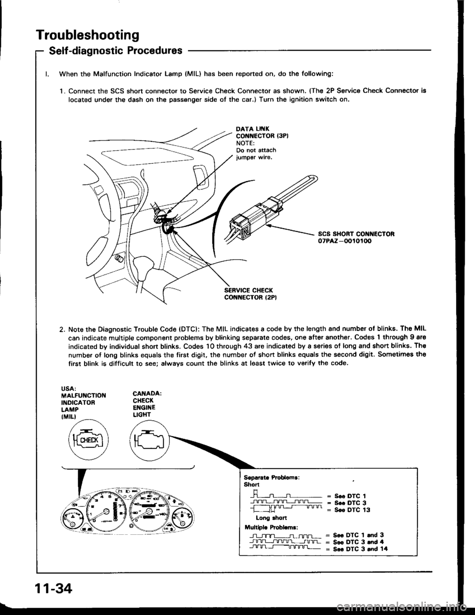
Self-diagnostic Procedures
When the Malfunction Indicator Lamp {MlL) has been reported on, do the following:
'1. Connect the SCS short connecto. to Service Check Connector as shown. (The 2P Service Check Connector is
located under the dash on the passenger side of the car.) Turn the ignition switch on.
DATA LII{KCONNECTOR (3PI
NOTE:Do not attachjumper wire.
2. Note the Diagnostic Trouble Code (DTC): The MIL indicates I code by the length 8nd numbsr ot blinks. The MIL
can indicate multiple component problems by blinking separate codes, one after another. Codes 1 through Igre
indicated by individual shon blinks. Codes 1O through 43 are indicated by a series of long and shon blinks. Th€
number of long blinks equals the first digit, the number ot short blinks equals the second digit. Sometimes the
firsr blink is difficult to see; always count the blinks at least twice to verify the code.
MALFUNCTIOI{INDICATORLAMP
CANADA:CHECKENGINELIGHTIMIL}
Sgprrate Prcbaomr:shT
-n-----n- =n- = s.o DTc 1
+!+1].TL;I!!=- = s.. Drc 3-L ,JU '" " " = Sce DTC 13
Long .hon
Multiplr Probl.ln.:
J-l_tx-TL-n-ffu-r- = S€. DTC 1 lnd 3-J.rrU-L-r]tltlr'l- __-tnrua = Sce DTC 3 and 4Jll-lrl-t-----Tt/'tnj]_ = S.. DTC 3 lnd 14
11-34
Page 227 of 1413
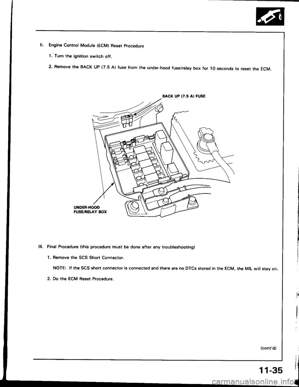
Engine Control Modute {ECM) Reset procedure
1 . Turn the ignition switch otJ.
2' Remove th€ BACK UP (7.5 A) fuse trom the unde.-hood fuse/relay box for lo seconds to reset the EcM.
BACK UP I7.5 AI FUSE
UNDER-HOOOFUSE/RELAY BOX
Final Procedure lthis procedure must be done after any troubleshooting)
1. Remove the SCS Short Connector.
NOTE: lf the SCS short connector is connected and there are no DTCS sto.ed in the ECM, the MIL will stav on.
2. Do the ECM Reset Procedure.
11-35
Page 228 of 1413
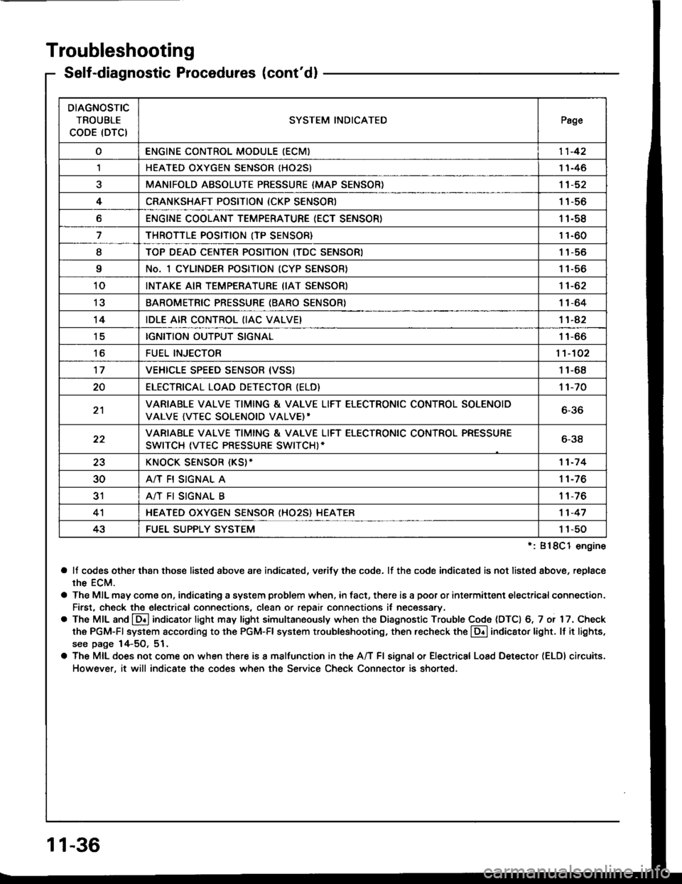
Troubleshooting
Self-diagnostic Procedures (cont'dl
':818C1 engine
a lf codes other than those listed above are indicated, verifv the code. lf the code indicated is not listed above, replace
rhe ECM.
a The MIL may come on, indicating a system problem when, in fact, there is a poor or intermittent electricalconnection.
First, check the electrical connections, clean or repair connections it necessary.
o The MIL and @ indicator light may light simultaneously when the Diagnostic Trouble Code (DTC) 6, 7 or 17. Check
the PGM-Fl system according to the PGM-Fl system troubleshooting, then recheck the l!! indicator light. ll it lights,
see page 14-5O, 51.
a The MIL does not come on when there is a malfunction in the A/T Fl signal or Electrical Load Detector (ELDI circuits.
However, it will indicate the codes when the Service Check Connector is shorted.
DIAGNOSTIC
TROUBLE
CODE (DTCISYSTEM INDICATEDPsge
oENGINE CONTROL MODULE IECM)11-42
,lHEATED OXYGEN SENSOR IHO25)1 1-46
aMANIFOLD ABSOLUTE PRESSURE {MAP SENSOR)11-52
4CRANKSHAFT POSITION (CKP SENSOR)1 1-56
oENGINE COOLANT TEMPERATURE (ECT SENSOR)11-58
THROTTLE POSITION (TP SENSOR}11-60
ITOP DEAD CENTER POSITION (TDC SENSORI1 1-56
9No. 1 CYLINDER POSITION (CYP SENSOR)1 1-56
10INTAKE AIR TEMPERATURE (IAT SENSOR)11-62
13BAROMETRIC PRESSURE (BARO SENSOR}1|-64
14IDLE AIR CONTROL (IAC VALVE}11-42
tcIGNITION OUTPUT SIGNAL11-66
toFUEL INJECTOR1't-102
17VEHICLE SPEED SENSOR {VSSI11-68
20ELECTRICAT LOAD DETECTOR (ELD)'t 1-70
21VARIABLE VALVE TIMING & VALVE LIFT ELECTRONIC CONTROL SOLENOID
VALVE {VTEC SOLENOID VALVE)'6-36
22VARIABLE VALVE TIMING & VALVE LIFT ELECTRONIC CONTROL PRESSURE
SWITCH (VTEC PRESSURE SWITCHI-6-38
23KNOCK SENSOR {KS}-11-7 4
30A/T FI SIGNAL A11-76
3'rA/T FI SIGNAL B1 1-76
4'lHEATED OXYGEN SENSOR (HO25} HEATER11-47
43FUEL SUPPLY SYSTEM1 1-50
11-36
Page 229 of 1413
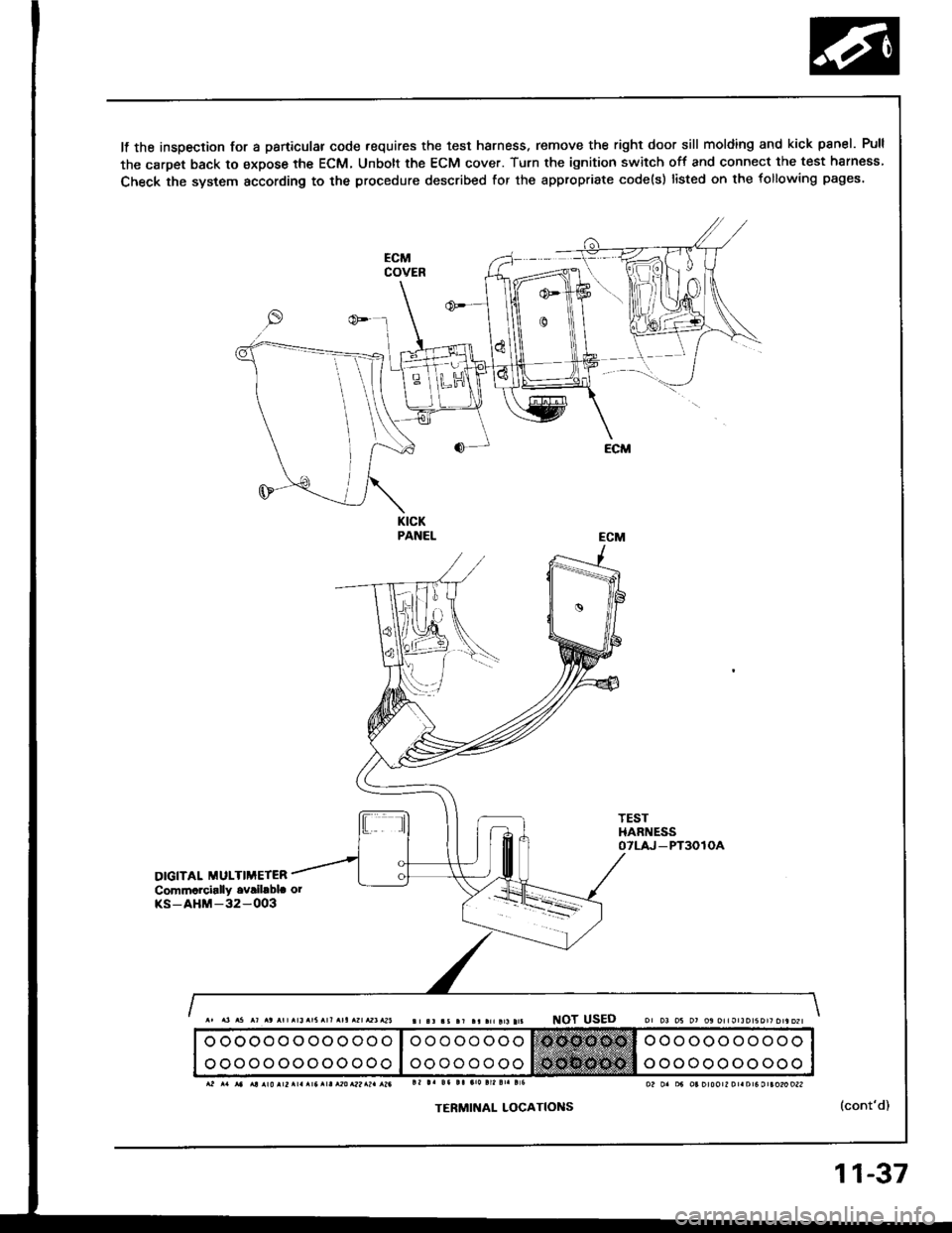
It the inspection for a particular code requires the test harness. remove the right door sill molding and kick panel. Pull
the carpet back to expose the ECM, Unbott the ECM cover. Turn the ignition switch off and connect the test harness
Check the system according to the procedure described for the appropriate code(s) listed on the following pages.
KICKPANEL
TESTHARNESSOTLAJ _PT3OlOA
DIGITAL MULTIMETERCommarcially ovribbla orKS-AHM-32-OO3
NOT USED
TERMINAL LOCATIONS(cont'd)
o oooooooooooo
ooooooooooooo
oo o oo ooo
oooooooo
ooooooooooo
ooooooooooo
11-37