Fast idle HONDA INTEGRA 1994 4.G Workshop Manual
[x] Cancel search | Manufacturer: HONDA, Model Year: 1994, Model line: INTEGRA, Model: HONDA INTEGRA 1994 4.GPages: 1413, PDF Size: 37.94 MB
Page 24 of 1413
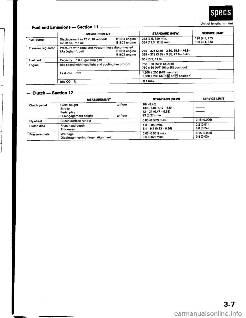
Fuel and EmissionsSection 11
ClutchSection 12
Unit ot length: mm {in)
MEASUREMENTsTAt{ItAno (NewlSERVICE UMIT
.u.l pumpDisolacoment in l2 V, 10 seconds 81881 engine
m, (fl oz, lmp oz) 818C1 engins222 17 .5,7 -81 min. | 12011.1' 1'21
364 (12.3, 12.8) min. I too (:.1, g.st
F aa3uro rggulatorPressure with regulator vacuum hose disconnected
kPa (kgflcm', psi) Bl8Bl engineBl8Cl engin€275 - 32a 12.8 -3.9,39.6 - 46.9)329 - 378 (3.35 - 3.85, 47.6- 5.47)
tualt6nkCaprcity, {US gal, lmp gal)50 (13.2, 11.01
En9in6ldle sDeed with headlight and cooling fan ofi rpm7501 50 (M/T: neut..ll750I 50 {A/T: E or E position}
Fast idle rpm1,600 i 2(x' lM/T: nsurr6l)l,eoo I 200 (A/T: E or E po6itioo)
ldl6 CO %0.1 max.
MEASUREMENTSTAM'Ad' IiEWISERVICE UMIT
clutch padslP6d6l height to lloor
SirokePedal play
Disengagement height to floor
164 (6.46)
130 - 140 (5.12 - 5.51)12 - 21 (0.47 - 0.83)83 (3.27) min.
Clutch sudace runout0.05 10.002) max,0.'15 (0.006t
clutch discRiv€t h€ad depthThickness
1.3 (0.05) min.8.4- 9.1 (0.3 - 0.36)0.2 (0.011
6.0 (0.24)
Pr6sur6 plat€WarpageOiaphragm spring linger alignment0.03 (0.001) mrx.0-6 (0.02) ma*0.15 (0.006)
0.8 (0.03)
{n+
3-7
Page 187 of 1413

ENGINE COMPARTMENT HOSE CONNECTIONS:
Bl88l engine:FAST IDLETHERMOVALVE
THERMOSTATHOUSIITGIDLE AIR CONTROLIIAC} VALVE
O'RINGReplace.
BREATHER PIPE
O-RINGReplace.
HEATER HOSES
818C1 engine:
ENGINE OILCOOLER
IAC VALVE
HEATER BYPASSPIPE
FAST IDLETHERMOVALVE
THERMOSTATHOUSING
BREATHER PIPE
HEATEB HOSES
10-3
Page 197 of 1413
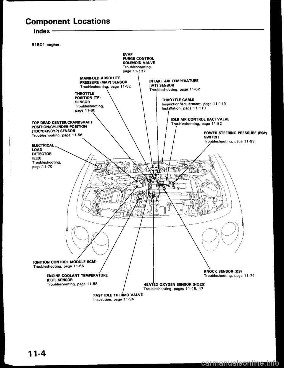
Component Locations
lndex
B18Cl ongino:
THROTTLEPOSITION (TP}
SENSOR
MANIFOLD AESOLUTEPRESSURE (MAPI SENSOR
Troubleshooting, page 1 1-52
EVAPPURGE CONTROLSOLEiIOID VALVETroubleshooting,page 11-137
VALVE
INTAKE AIR TEMPERATURE
IIAT) SENSORpage 11-62
THROTTLE CABLEInspection/Adiustment, page 'l 1-1 19
lnstallation, page 1 1-1 19
IOLE AIF CONTROL (IACI VALVETroubleshooting. page 1 1 -82
Troubleshooting,page 1 1-6O
TOP DEAD CENTER/CRANKSHAFTPOSITION/CYLINDER POSITION
{TDC/CKP/CYPI SEI{SORTroubl€shooting. Page 1 1 -56POWER STEERING PRESSURE (PS'I
swtTcHTroubleshooting, page 1 1-93ELECTRICALLOADDETECTORIELD}Troubleshooting,page.1 1-70
IGNITION CONTNOL MODULE OCMI
Troubleshooting, Psge 1'l-66
ENGIT{E COOLANT TEMPERA
{ECT} SEI{SORTroubleshooting, Pag€ 1 1-58
sElrlsoR tKslTroubfeshooting, page 1 1 -7 4
HEATED OXYGEN SENSOR (HO2S}
Troubleshooting, pages 11-46, 47
FAST IDLEInspection, page 1 'l -94
11-4
Page 201 of 1413
ENGINECOOLANT
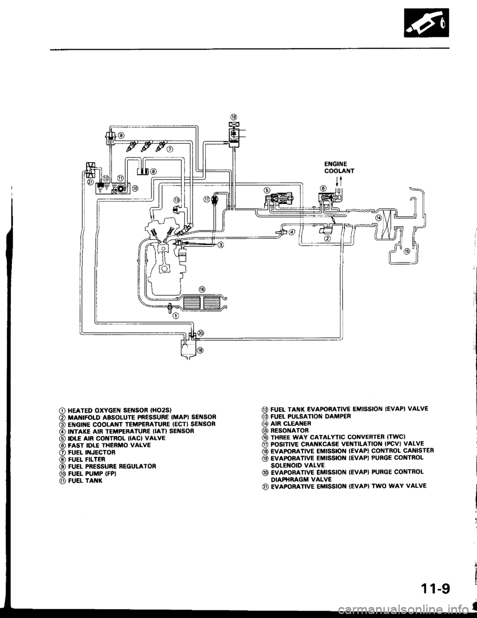
@ FUEL TAI{K EVAPORATIVE EMISSION (EVAP} VALVE
G) FUEL PULSATION DAMPER
@ AIR CLEANER
@) RESONATOR
@ THREE WAY CATALYTIC CONVEnTER (TWC)
o POS|TIVE CRANKCASE VEITITILAT|ON IPCV) VALVE
@ EVAPOBATIVE EMISSION IEVAP) COI{TROL CANISIER
@ EvApoRATrvE EMrssroN IEVAP) PURGE coNTRoL
SOLENOID VALVE
@ EVAPORATTVE EMISSION (EVAP) PURGE CONTROL
DIAPHRAGM VALVE(iD EVAPORATIVE EMISSION (EVAPI TWO WAY VALVE
|l
U]
HEATED OXYGEI{ SEI{SOF (HO2S}
MANIFOI.D ABSOLUTE PRESSURE (MAP) SEI{SONENGINE COOLANT TEMPERATURE IECT} SENSORINTAKE AIR TEMPERATURE IIAT} SEI'ISORIDLE AIR CONTROL IIAC) VALVEFAST IDLE THERMO VALVEFUEL II{JECTORFUEL FILTERFUEL PRESSURE REGULATONFUEL PUMP IFP)FUEL TAI{K
11-9
Page 203 of 1413
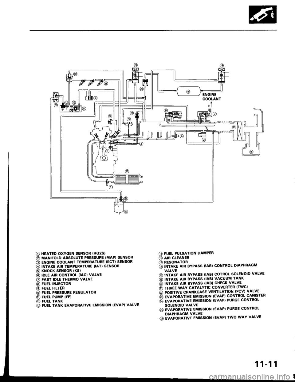
G) FUEL PUI-SATION DAMPER
@ AIR CLEANER(D RESONATOR6 imrlre arR Bypass (tAB) coNTRoL DIAPHRAGM
VALVE(D) IITITP IIN BYPASS {IAB) COTROL SOLENOID VALVE
ds) INTIXT AIR EYPASS TIABI VACUUM TANK
rio'l rnrarg ltn BYPASS (lABl cHEcK vALvE
6 rsnee wav cATALYTtc coNvERTER lrwc)
6 posrnve cRAf{KcAsE vENTILATIoN {Pcv) vALVE
6 evlponlrtve EMtsstot{ tEvAPl coNTBoL cANlsrER
6 evlponltvE EMtssloN {EvAP} PURGE coNTRoL
SOLENOID VALVE6i EVAPORATIV€ EMISSION (EVAPI PURGE CONTROL
DIAPHRAGM VALVE
6o ivlpoalrtve Eutsstof{ IEVAPI rwo wAY vALvE
c) HEATED OXYGEN SENSOR lHO2Sl
€) MANIFOLD ABSOLUTE PRESSURE IMAPI SENSOB
O EI{GINE COOLANT TEMPERATURE {ECT} SENSOR
€) INTAKE AIR TEMPERATURE {IAT) SENSOR
@ KNOCK SENSOR tKSl
@ IDLE alR coNTRoL llAcl vALvE
O FAST IDLE THERMO VALVE
@ FUEL INJECTOR
@ FUEL FILTER
@ FUEL PRESSURE REGULATOR
O) FUEL PUMP (FPI
@) FUEL TANK
@ FUEL TANK EVAPORATIVE EMISSION IEVAPI VALVE
11-11
Page 224 of 1413
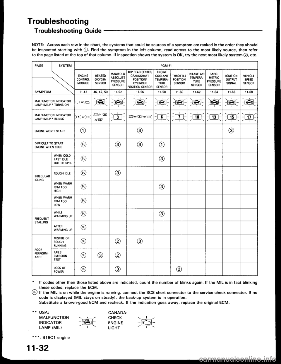
Troubleshooting
Troubleshooting Guide
NOTE: Across each row in the chart. the systems that could be sources of a symptom are ranked in the order they should
be inspected staning with O. Find the symptom in the left column, read across to the most likely source. then refer
to the page listed at the top of that column. lf inspection shows the system is OK, try the next mosr likely system O, etc,
* lf codes other then those listed above are indicated, count the number of blinks again. It the MIL is in fact blinking
^ these codes, replace the ECM.
qy, lf the MIL is on while the engine is running. connect the SCS shon connector to the service check connector. It no
code is displayed {MlL stays on steady), the back-up system is in operation.
Substitute a known-good ECM and recheck. lf the indication goes away, replace the original ECM.
USA:
MALFUNCTION
INDICATOR
LAMP {MIL)
CANADA: ----l CHECK-ltGl- ENGTNE- | - LTGHT
- { -1t-
* * *: 818C1 engine
1-32
SYMPTOM
PGM.FI
ENGINECONTROLMOOULE
HEATEOOXYGENSENSOR
MANIFOLOAESOLUTEPRESSURESENSOR
TOP DEAD CINTTR/CRANKSHAFTPOSTT|ON/CYLINDERPOSITION SENSOR
ENGINECOOLANTTEMPfRA.TURTSENSOR
THROTTTEPOStTtONSENSOR
INfAKE AIRTEMP€RA.TUREsar,rs0R
BARO.METRICPRESSURESENSOR
IGNITIONOUTPUTSIGNAL
vEHtct-ESPfEDSENSOR
11.4246, 47,5011-56l1-581l-6011-6211-641t-661r-68
MALFUNCTION INOICATORLAMP (MIU" TURNS ON1 lor:t:]:lrmr:- i;:i'-tK3t-16l-16l'-\-16l/-----\
-r:+r-
-{"Pr:-o_-16l-.z-\r6t/_-\
MALFUNCTION INOICATORLAMP (MIL)'' BLINKS:O. or-8.-D:o.:@.
o, O'l3l/__-\.E-o.:O: or tr]--i !l/ -i-\| 7 t-/__-\
--l-l-l r0 I/----\| 13 |z_---\
\.--r--l
I r5 t-/.---\-t 17 t-/-]-\
ENGINE WON'T STAffTo@@
DIFFICULT TO STARTENGIN€ WHEN COLO@@(9)o
IRREGULARIDLING
WHEN COTDFAST IDLEouT 0f sPtc@@
ROUGH IDLE@o
RPM TOOHIGH@@
RPM TOOLOW@
FREOUENTSTALLING
WHILE@@
AFTER@
POOnPERFOEM.ANCE
MISFIRE ORROUGHRUNNING@@@
FAITSEMISSIONTEST@@@
Loss 0FPOWER@@@
Page 267 of 1413
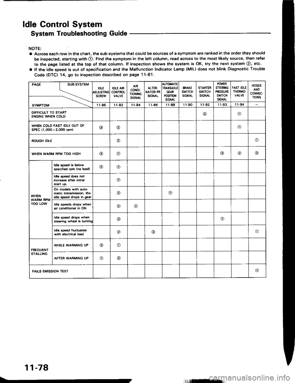
ldle Gontrol System
System Troubleshooting Guide
NOTE:
a Acrosa each row in the chan, the sub-systems that could be sources of a symptom are ranked in the order they should
be inspected, starting with O. Find the symptom in the left column, read across to the most likely source, then reler
to the page listsd at ths top ot that column. It inspection showa the system is OK, try the next system @, etc.
a lf the idle speed is out of sp€cification and th€ Malfunction Indicator Lamp {MlL) does not blink Diagnostic Trouble
Code (DTC) 14, 9o to inspection describ€d on pags 1 1-81.
PAGE
SYMPTOM
IDTIOJUSTIiSCREW
IDLE AIRc0NTROt-
AIRcoN0fTtoNtitcSIGNAL
ALTER.NAION FNSIGNAL
AUTOMATICIRAI{SA(LEGtARP0sm0 stGIAt
ERAK€swrTcHSIGNAL
STARTERswtTcHSIGNAT
POWERSTEERII'IGPffESSUREswncHSIGNAL
FAST IOLETHERMO
HOSESANOCONNEC.TIONS
11-9511-4211-841 1-8611-8811-9011-92I 1-9311-94
DIFFICULT TO STARTENGINE WHEN COLD@o
WHEN COLD FAST IDLE OUT OFSPEC l1,0OO- 2,0OO rpm|o@o
ROUGH IDLEo
WHEN WARM RPM TOO HIGHooo
WHEN
TOO LOW
ldl6 3p6od b b€lowspecitisd rpm (no loadl@o
ldla 5p66d doos nolincraas€ alter initialo
On mod6l3 with auto-matic transmBsion, thsidlo sp€ed drops in 963ro
ldl6 sp€eds drops when8ir condilioner in ONoo
ldls spo6d drops when6ts6iing wh66l i6 turninC@o
ldla spoed lluctust63with alactrical loado
FREOUENTSTALLING
WHILE WARMING UP@o
AFTER WARMING UPo@
FAILS EMISSION TESTo
11-78
.,Hilffirl|,
Page 268 of 1413
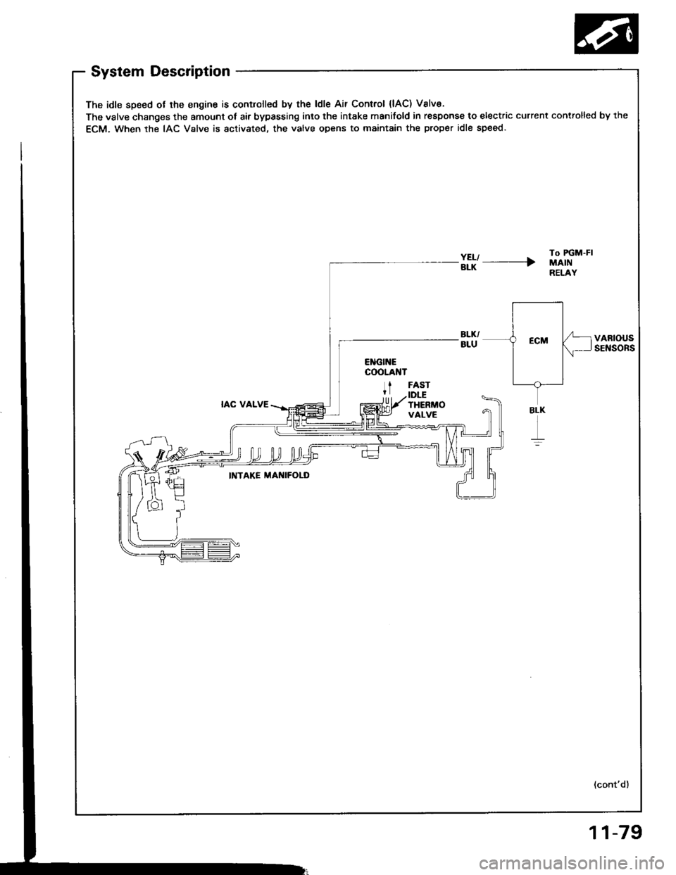
System Description
The idle speed ot lhe engine is controlled by the ldle Air Control {lAC) Valve.
The valve changes the amount ot air bypassing into the intake manifold in response to electric current controlled by the
ECM. When the IAC Valve is activated, the valve opens to maintain the proper idle speed.
#l' ----rTo FGM-FIMAINRELAY
VARIOUSSENSORS
IAC VALVE
FASTIDLETHERMOVALVE
INTAKE MAI{IFOLD
(cont'd)
BLK
r
11-79
Page 269 of 1413
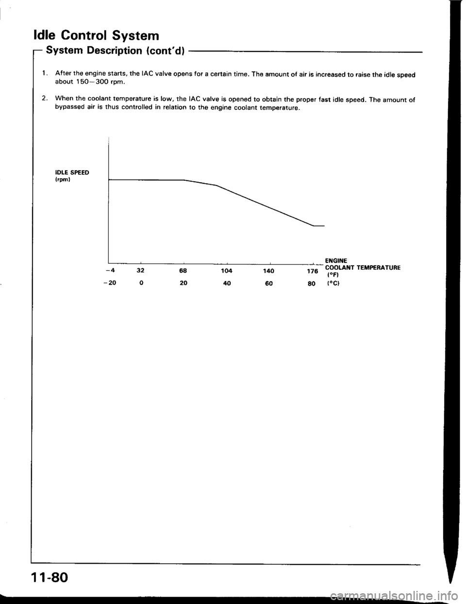
ldle Control System
System Description (cont'd)
1 . Atter the engine slarts. the IAC valve opens for a censin time, The amount ot air is increased to raise the idle soeedabout 15O-3OO rom.
2. When the coolant temperature is low, the IAC valve is opened to obtain the proper fast idle speed. The amount ofbypassed air is thus controlled in relation to the engine coolant temperature.
IDI-E SPEEDlrpm)
176
80
ENGINECOOLANT TEMPERATURE
t"Fl(oct
11-80
Page 270 of 1413
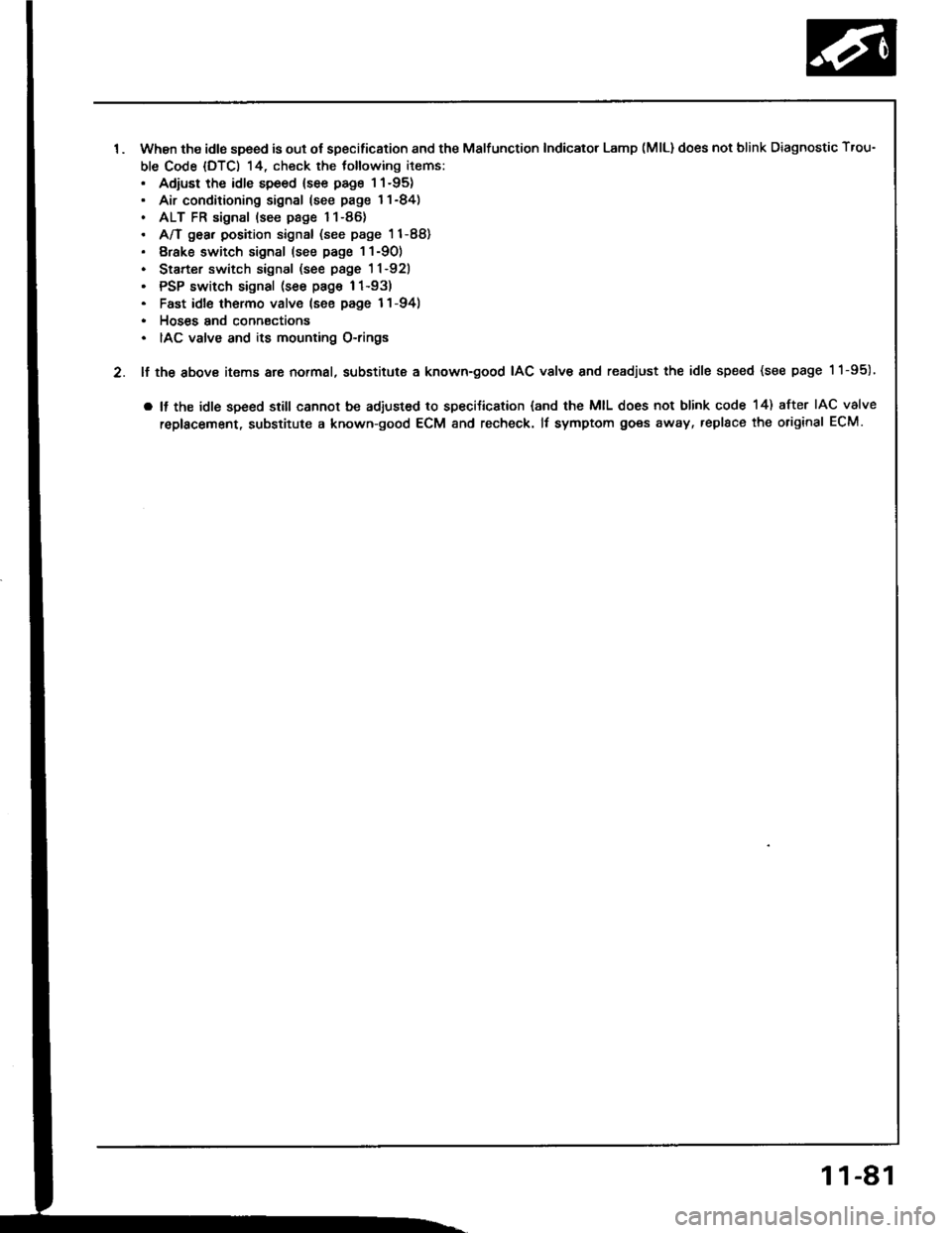
1. when the idls speed is out of specification and the Malfunction Indicator Lamp (MlLldoes not blink Diagnostic Trou-
ble Code (DTC) 14, check the tollowing items:. Adiust the idle speed {see page I1-95). Air conditioning signal (see page l1-84). ALT FR signal (see page '11-86)
A/T gea, position signal (see page 11-88)
Erake switch signal (see page 1 1-90)
Starter switch signal (see page 1l-921
PSP switch signal (see page 1 1-93)
Fast idl6 thormo valve (see page l1-94)
Hoses and connsctions
IAC valve and its mounting O-rings
2. lf the above items are normal, substitute a known-good IAC vslv€ and readjust the idle speed (see page 11-95)'
. It the idle speed srill cannot be adjusted to speciJication (and the MIL does not blink code 14) after IAC valve
roplacement, substitute a known-good ECM and recheck. It symptom goes away, replsce the original ECM.
1 1-81