bolt pattern HONDA INTEGRA 1994 4.G Workshop Manual
[x] Cancel search | Manufacturer: HONDA, Model Year: 1994, Model line: INTEGRA, Model: HONDA INTEGRA 1994 4.GPages: 1413, PDF Size: 37.94 MB
Page 83 of 1413
!
1.
2.
Camshafts
Inspection
Loosen the adjusting screws.
Remove the camshaft holders and the rocker arms
NOTE: Mark the rocker arms before removing
them.
Reinstall the camshaft and holders. Tighten the
camshaft holder bolts in a crisscross pattern, begin-
ning with the inner bolts.
9.8 N.m (1.0 kgf.m,7.2 lbf.ft)
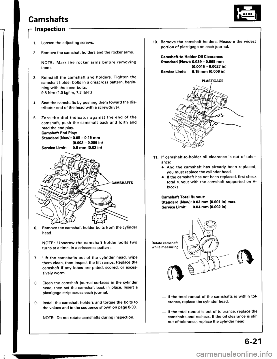
Seat the camshafts by pushing them toward the dis-
tributor end of the head with a screwdriver.
Zero the dial indicator against the end of the
camshaft. push the camshaft back and forth and
read the end play.
Camshalt End Play:
St.ndard lNow): 0.05 - 0.15 mm
(0.002 - 0.006 inl
Seivice Limit: 0.5 mm {0,02 in)
Remove the camshaft holder bolts from the cylinder
head.
NOTE: Unscrew the camshaft holder bolts two
turns at a time, in a crisscross pattern.
Lift the camshafts out ot the cylinder head. wipe
them clean, then inspect the lift ramps. Replace the
camshaft if any lobes are pitted, scored, or exces-
srvely worm
Clean the camshaft journal surfaces in the cylinder
head, then set the camshaft back in place. Insert a
plastigage strip across each iournal.
Install the camshaft holders and torque the bolts to
the values and in the sequence shown on page 6-30.
NOTE: Do not rotate camshafts during inspection.
-
6-21
10.Remove the camshaft holders. Measure the widest
ponion of plastigage on each journa..
Camshaft-to Holder Oil Clearance:
Standard lNewl: 0.039 - 0.069 mm(0.0015 - 0.0027 in)
Sarvico Limit 0.15 mm {0.006 inl
11. lf camshaft-to-holder oil clearance is out of toler
ance:
. And the camshaft has already been replaced,
vou must replace the cylinder head.
. lf the camshaft has not been replaced, first check
total runout with the camshaft supported on V-
blocks.
Clmshaft Total Runout:
StEndard {New): 0.03 mm (0.001 inl max'
Servico Limit: o.Oil mm {0.002 inl
- lf the total runout of the camshafts is within tol-
erance, replace the cylinder head.
- lf the total runout is out of tolerance, replace the
camshafts and recheck. lf the oil clearance is still
out of tolerance. replace the cylinder head.
PLASTIGAGE
Page 91 of 1413
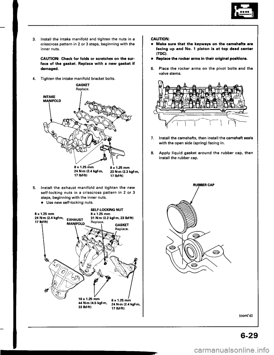
Install the intake manifold and tighten the nuls in a
c.isscross pattern in 2 or 3 steps, beginning with the
inner nuts.
CAUTION: Check to. fold3 or 3cratchc! on ihc aur-
taco ol tho ga3kot. Roplscs with a nlw gaeket if
damagod.
Tighten the intake manifold bracket bolts.
GASXETReplace.
E x 1.25 mm 8 x 1,25 mm2ir N.m l2.it kg{.m, 23 N.m 12.3 kgf.m.17 tbf.ftl 17 tbl.frt
Install the exhaust manifold and tighten the new
self-locking nuts in a crisscross pattern in 2 or 3
steps, beginning with the inner nuts.
. Use new self-lockiflg nuts.
4.
5.
8 x 1.25 mm24 N.m (2,a kgf.m,
SELF.LOCKING NUT8 x 1.25 mm31 N.m (3.2 kgt m,23lbfftlEXHAUST11Replace.
l0 x 1.25 mma,t N.m 14.5 kgf.m,33 tbt.ft)
GASKEIReplace.
8 x 1.25 mm2il N.m 12.4 kg{.m,17 rbtftl
m
CAUTION:
. Mlka 3uro thrt thc k.ywlyr on tho c.mthlttr lrc
facing up .nd No. I pi3ton i3 8t top d.rd clnt.r(TDCt.
. Rcphct th! rocksr armr in thsir o.iginal potltlom.
6, Place the rocker arms on the oivot bolts and ths
valve stems.
lnstallths camshafts, then installth€ camshaft sosls
with ths open side (spring) facing in.
Apply liquid gasket around the rubber cap, then
installthe rubber cao.
7.
8.
(cont'd)
6-29
Page 126 of 1413
Camshafts
Inspection
4,
5.
9.
1.
Remove the bolts, then remove the camshaft hold-
ers from the cvlinder head.
NOTE: Unscrew the camshaft holder bolts two
turns at a time, in a crisscross pattern.
Lift camshaft out of cylinder head. wipe clean, then
inspect lift ramps. Replace camshaft if lobes are pit-
ted, scored, or excessively worn.
Clean the camshaft bearing surfaces in the cylinder
head. then set camshaft back in place.
Place a plastigage strip across each journal.
Install the camshaft holders, and then tighten the
bolts to the specified torque as shown in the left
column on this page.
NOTE: Do not rotate camshafts during inspection.
Remove the camshaft holders. Measure widest Dor-
tion of plastigage strip on each journal.
Camshaft-to-Holder Oil Clearance:
Standard {New): 0.050 - 0.089 mm
{0.002 - o.Ooil in)
Sswice Limit: 0.15 mm (0.006 in)
(cont'dl
NOTE:
. Do not rotate the camshaft during inspection.
. Remove the rocker arms and rocker shafts.
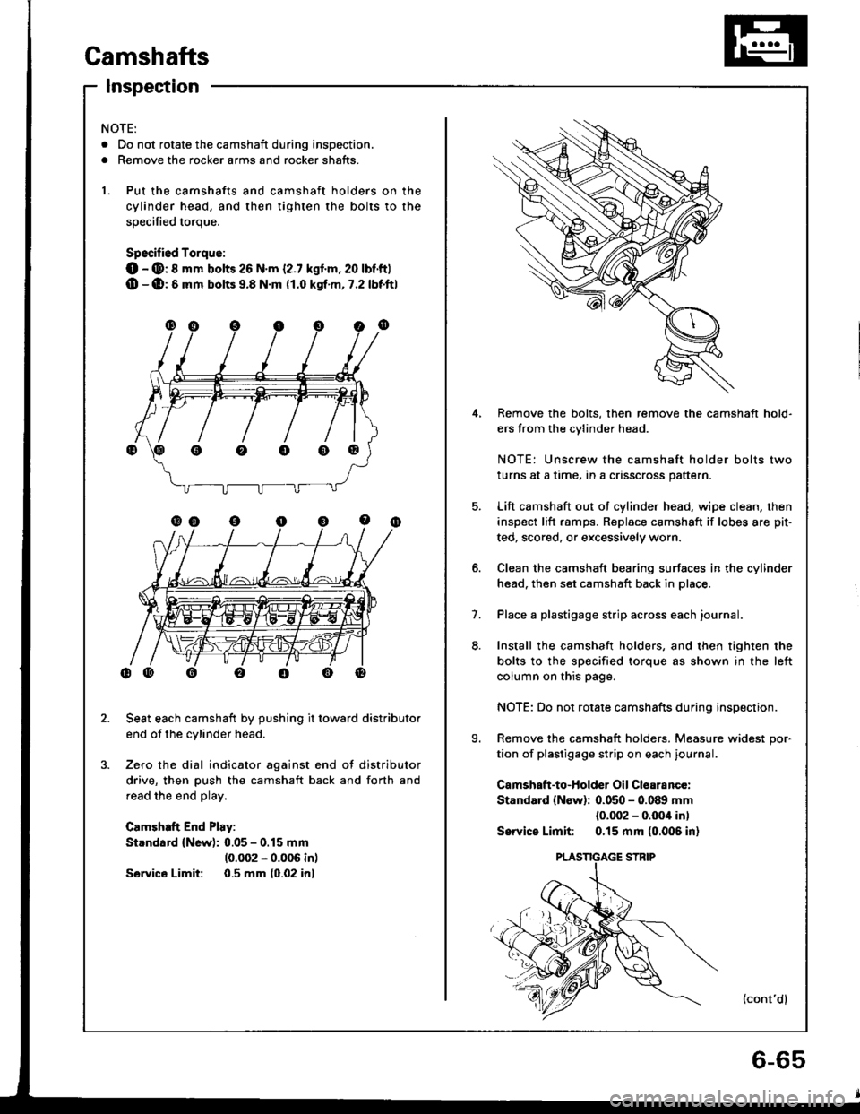
1. Put the camshafts and camshaft holders on the
cylinder head, and then tighten the bolts to the
soecified torque.
Specified Torque:
O - @: 8 mm bolts 26 N.m {2.7 kgl.m,20 lbt'ftl(D -(D:6 mm bolts 9.8 N.m {1.0 kgt.m, 7.2 lbf'ftl
Seat each camshaft by pushing it toward distributor
end of the cylinder head.
Zero the dial indicator against end of distributor
drive, then push the camshaft back and forth and
read the end play.
Camshaft End Play:
Standard (New): 0.05 - 0.15 mm
10.002 - 0.006 inl
Sawics Limit: 0.5 mm (0.02 inl
oooo@
Page 136 of 1413
lnstallation
Installthe cylinder head in the reverse order of removal:
NOTE:
. Always use a new head and manifold gasket.
. The cylinder head gasket is a metal gasket Take care
not to bend it.
. Rotate the crankshaft, set the No. 1 piston at TDC
(page 6-51).
. Do not use the middle cover and lower cover for
storing items disassembled.
. Clean the middle cover and lower cover before instal-
lation.
a Replace the washer when damaged or deteriorated
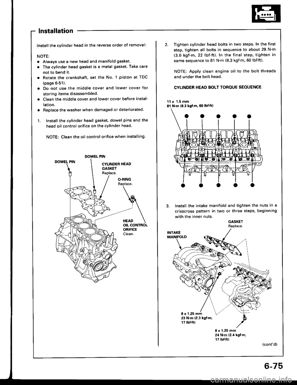
1. tnstall the cylinder head gasket. dowel pins and the
head oil control orifice on the cylinder head
NOTE: Clean the oil control orifice when installing.
O.RINGReplace.
HEADOIL CONTROLORIFICECloan.
2. Tighten cylinder head bolts in two steps. In the first
step, tighten all bolts in sequence to about 29 N'm
(3.0 kgf.m.22 lbf'ft). In the final step, tighten in
same sequence to 81 N.m (8.3 kgnm.60 lbf'ft).
NOTE: Apply clean engine oil to the bolt threads
and under the bolt head.
CYLINDER HEAD BOLT TOROUE SEOUENCE
11 x 1.5 mm81 N.m {8.3 kgf.m,60 lbf ft)
Install the intake manifold and tighten the nuts in a
crisscross pattern in two or three steps, beginning
with the inner nuts.
GASKETRePlace
8 x 1.25 mm23 N.m 12.3 kgl.m.17 tbf.ftt
8 x 1.25 mm24 N,m 12.,4 kgf m,17 tbf.ft)(cont'd)
6-75
Page 165 of 1413
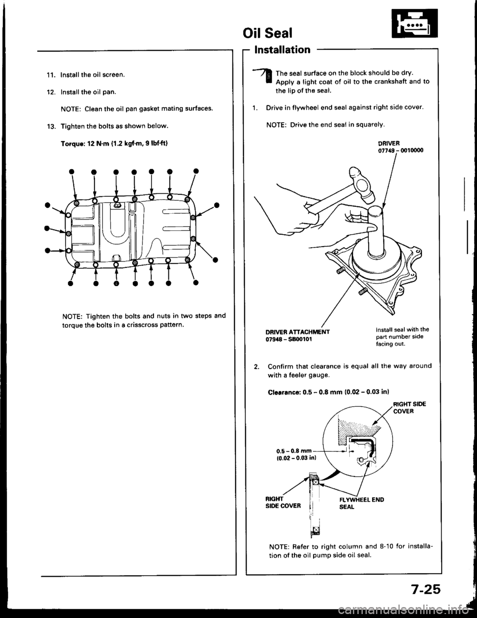
11.lnstallthe oil screen.
Installthe oil pan.
NOTE: Clean the oil pan gasket mating surfaces.
Tighten the bolts as shown below.
Torque: 12 N.m {1.2 kgf.m, 9 lbf'ft)
NOTE: Tighten the bolts and nuts in two steps and
toroue the bolts in a crisscross pattern
1'�I
Oil Seal
lnstallation
The seal surface on the block should be dry.
Apply a light cost of oil to the crankshaft and to
the liD of the seal.
Drive in flywheel end seal against right side cover.
NOTE: Drive the end seal in squarely.
DRIVER07t,49 - (xll(xtoo
2. Confirm that clearance is equal all the way around
with a fe€ler gauge.
Cler.6nce: 0.5 - 0.8 mm (0.02 - 0.03 inl
RIGHT SIDECOVER
NOTE: Reter to right column and 8-10 lor installa-
tion of the oil pump side oil seal.
lnstall sealwith thepart number sidetacing out.
7-25
Page 337 of 1413
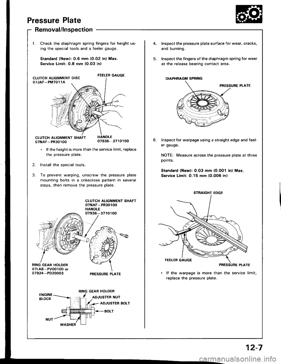
Pressure Plate
RING GEAR HOLDER07LAB-PVOOl OO or07924-PD20003
Removal/lnspection
Check the diaphragm spring fingers for height us-
ing the special tools and a feeler gauge.
Standard lNew): 0.6 mm (0.02 inl Max.
Service Limit: O.8 mm {O.O3 in}
FEELER GAUGE
07NAF-PR3010007936-3710100
. lf the height is more than the service limit, replace
the pressure plate.
2. Install the special tools.
3. To prevent warping, unscrew the pressure plate
mounting bolts in a crisscross pattern in several
steps, then remove the pressure plate.
CLUTCH ALIGNMENT SHAFT07NAF-PR30100HANDLE07936-3710'l OO
PRESSURE PLATE
CLUTCH ALIGNMENT OISCOTJAF_PM7011A
4.Inspect the pressure plate surface
and burning.
Inspect the fingers of the diaphrag
at the release bearing contact ar
DIAPHRAGM SPRING
Inspect for warpage using a stru
er gauge.
NOTE: Measure across the prer
pornls.
Standard (Newl: 0.03 mm (0.0
Sorvice Limit:0.15 mm (0.0O6
STRAIGHT EOGE
FEELER GAUGE
PI
lf the warpage is more than
replace the pressure plate.
6.
I surface for wear, cracks,
diaphragm spring for wear
nracr area.
PRESSURE PLAT€
straight edge and feef
pressure plate at three
0.001 in) Max.
)O6 inl
12-7
Page 339 of 1413
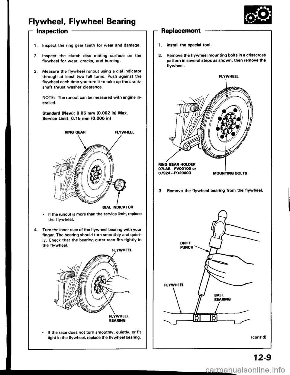
InspectionReplacement
Flywheel, Flywheel Bearing
Inspect the ring gear teeth for wear and damage.
Inspect the clutch disc mating surface on the
flywheel fo. wear, cracks, and burning.
Measure the flywheel runout using a dial indicator
through at least two full tu.ns. Push against the
Ilywheel each time you turn it to take up the crank-
shaft thrust washe. clearance.
NOTE; The runout can be measu.ed with engine in-
stalled.
Standard (ttlervl: O.O5 mm (O.002 inl Max.
Service Limit: 0.15 mm 10.006 inl
RING GEABFLYWHEEL
DIAL II{DICATOR
It the runout is more than the service limit, leplace
the flvwheel.
Turn the inner race of the flywheel bearing with your
finger. The bearing should turn smoothly and quiet-
ly, Check that the bearing outer race fits tightly in
the flvwheel.
FLYWHEELBEARING
It the race does not turn smoothly, quietly, or fit
tight in the flywheel, replace the flywheel bearing.
Install the special tool.
Remov€ the flywhe€l mounting bolts in a criascross
pattern in several steps 8s shown, then remove the
tlywheel.
MOUI{TII{G BOLTS
3. Remov€ the flywheel bsaring from th€ tlywheel.
(cont'd)
FLYWHEEL
12-9
Page 340 of 1413
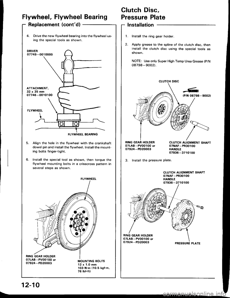
Clutch Disc,
l.
t
Flywheel, Flywheel BearingPressure Plate
Replacement (cont'd)Installation
Install the ring gear holder.
Apply grease to the spline of the clutch disc, theninstall the clutch disc using the special tools assnown.
NOTE: Use only Super High Temp Urea Grease (P/N
08798-9OO2).
CLUTCH DISC
RING GEAR HOLDEROTLAB-PVOOI O0 ot07924-PD20003
3. Instali the pressure
CLUTCH ALIGNMENT SHAFT07NAF-PR30100HANDLE07936-3710100
plate.
CLUTCH ALIGNMENT SHAFToTNAF-PR30100HANDLE
PRESSURE PLATE
12-10
4. Drive the new flywheel bearing into the flywheel us-
ing rhe special tools as shown.
DRIVER07749-O010000
ATTACHMENT.32x35mm07746-OOlO100
o.
5.
FLYWHEEL
Align the hole in the flywheel with the crankshaft
dowel pin and installthe flywheel. Installthe mount-
ing bolts finger-tight.
Install the special tool as shown, then torque the
flywheel mounting bolts in a crisscross pattern in
several steDs as shown.
MOUNTING BOLTS12 x 1.0 mm103 N.m 110.5 kgf.m,76 tbf.fr)
FLYWHEEL BEARING
FLYWHEEL
07936-3710100
t\_
Page 341 of 1413
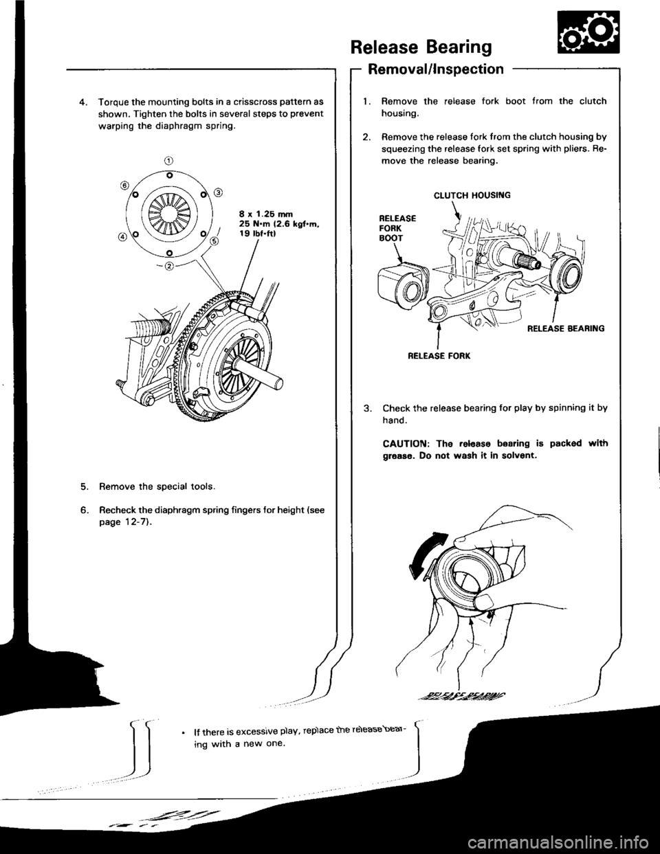
spection
release fork boot trom the clutch4. Torque the mounting bolts in a crisscross pattern as
shown. Tighten the bolts in several steps to prevent
warping the diaphragm spring.
8 x 1.25 mm25 N.m 12.6 kgt'm,19 tbt.ftl
2. Remove the release tork trom the clutch housing by
squeezing the release fork set spring with pliers. Re-
move the release bearing.
Check the release bearing for play by spinning it by
hand.
CAUTION: The release boaring i6 packed with
grease. Do not wash it in solvent.
Remove the special tools.
Recheck the diaphragm spring fingers tor height (see
page 12-7]..
Release Bearing
Removal/ln
1. Remove the
housing.
CLUTCH HOUSING
RELEASE FORK
-24/--2,t'.2424?'
IJ
l{ there is excessive plaY, rep)ace the rdease\Ear-
ing with a new one.
,F=:=
Page 352 of 1413
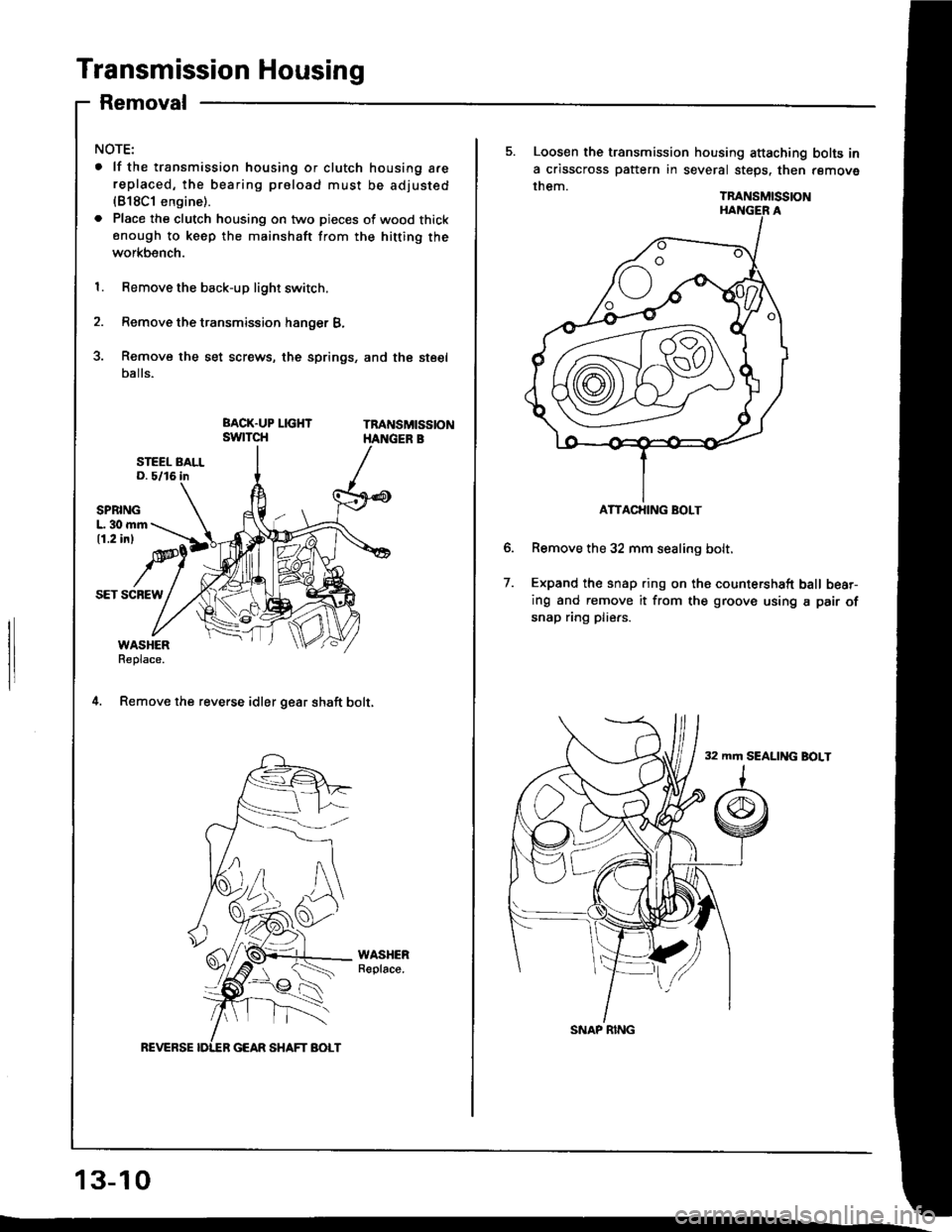
Transmission Housing
Removal
NOTE:
. lf the transmission housing or clutch housing a.ereplaced, the bearing proload must be adjusted(818C1 engine).
. Place the clutch housing on two pieces of wood thickenough to keep the mainshaft from the hitting the
workbench.
1. Remove the back-up light switch.
2. Remove the transmission hanger B,
3. Remove the set screws, the springs, and the steel
balls.
Tna sMtsstoN
SPBINGL. 30 mm11.2 inl
SET SCBEW
WASHERReplace.
4. Remov€ the reverse idler gear shaft bolt,
WASHERReplace.
REVERSE
L
13-10
ATTACHING BOLT
5. Loosen the transmission housing attaching bolts in
a crisscross pattern in several steps. then remove
them.TRANSMISSION
Remove the 32 mm sealing bolt.
Expand the snap ring on ths countershaft ball bear-
ing and remove it from the groove using a pair of
snap ring pliers.
32 mm SEALING BOLT
7.
SNAP RING