7.Remove the transmission jack.
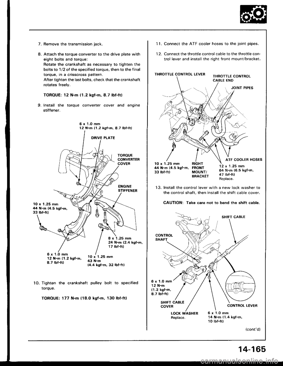
Attach the torque converter to the drive plate with
eight bolts and torque:
Rotate the crankshatt as necessary to tighten the
bolts to 1/2 of the specilied torque, then to the final
toaque, rn a cnsscross pattern.
After tighten the last bolts, check that the crankshaft
rotates freely.
TOROUE: 12 N.m {1.2 kgl.m.8.7 lbf.ft}
Install the torque converte. cove. and engine
stiffener.
L
9.
6 r 1.O mm12 N.m 11.2 kgt.m, 8.7 lbl.ltl
10.
12 N.m 11.2 kgf.m,8.7 rbt.ft)
Tighten the crankshaft pulley bolt to specified
rorque.
TOROUE: 177 N.m {18.O kgt.m, 130 lbf'ft}
10 x 1.25 mm44 N'm {4.5 kgf.m.33 rbt'frl
8 x '1.25 mm24 N.m (2.4 kgl.m,17 tbf.trl
lO x '1.25 mm43 N.m14.4 kgf.m, 32 lbf.ltl
11. Connect the ATF cooler hoses to the joint pipes.
12. Connect the throttle control cable to the throttle con-
trol lever and install the right front mount/bracket.
THROTTLE CONTROL LEVERTHROTTLE CONTROLCABLE END
JOINT PIPES
12 x 1 .25 mm64 N.m {6.5 kgf.m,47 tbf.ftlReplace.
ATF COOLER HOSES10 x 1.25 mm RIGHT44 N.m (4.5 kgf'm, FRONT33 rbl.ftl MoUNT/BRACK€T
t5.Install the control lever with a new lock washer to
the control shalt. then install the shift cable cover.
CAUTION: Take care not to bend the shift cable.
CONTROLSHAFT
SHIFT CABLE
CONTROL LEVER
6 x 1.0 mm12 N.m{1.2 kgf.m,8.7 lbl.rr)
SHIFT CABLECOVER
LOCK6 x 1.0 mm14 N.m 11.4 kgl.m,10 lbf.fr)
(cont'dl
Replace.ASHER
14-165
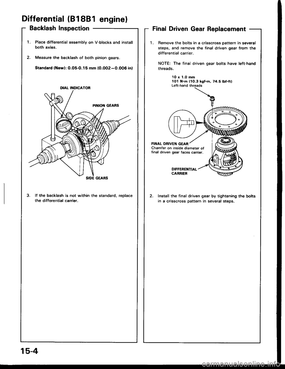
'1.Place difterential assembly on V-blocks and install
both axles.
M€asure the backlash of both pinion gears.
Standard (New):0.05-O.15 mm (0.OO2-0.006 inl
3. It the bscklssh is not within the standard, reDlace
the differential carrier.
DIAL II{OICATOR
Differential (818B1 enginel
Backlash InspectionFinal Driven Gear Replacement
1.Remove the bolts in a crisscross Datt€rn in several
steps, and remove the final driven gear from the
differential carrier.
NOTE: The final driven gear bolts have left-hand
threads.
10 x 1.0 mm101 N.m llO.3 kgl.m, 74.5 lbf.ftlLelt-hand threads
FINAL DRIVEIII GEARChamfer on inside diameter otlinal driven gear taces carrier.
DIFFEREI{TIALCARBIER
Install the final driven gear by tightening the bolts
in a c.isscross pattern in several steps.
15-4
Differential (818C1 enginel
Backlash Inspection
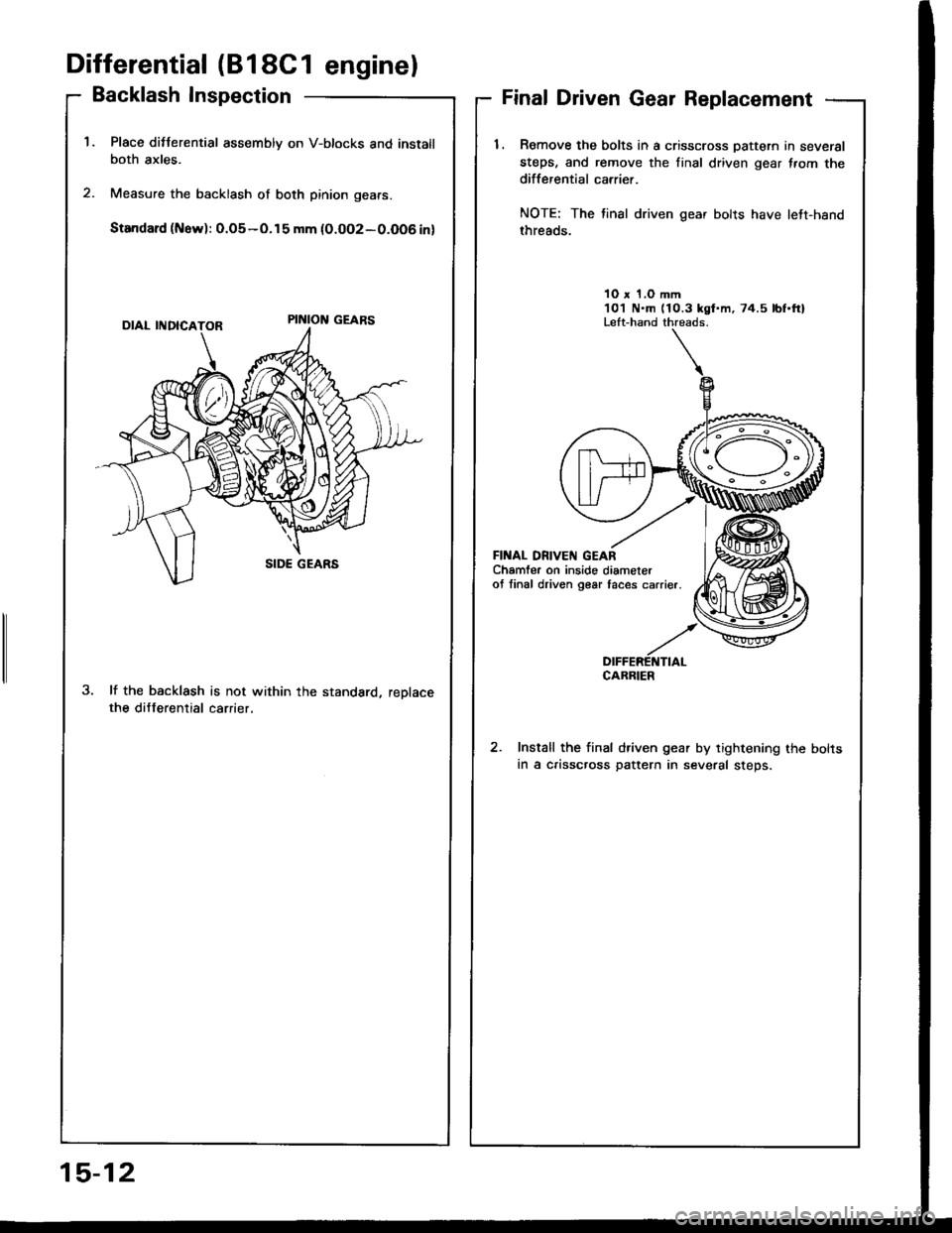
Place ditterential assembly on V-btocks and instatlboth axles.
Measure the backlash of both pinion gears.
Standard (Now): 0.o5-o.15 mm {0.oo2-0.O06 in)
lf the backlash is not within the standard, reDlacethe differential carrier,
Final Driven Gear Replacement
1. Romove the bolts in a crisscross Dattern in several
steps, and remove the tinal driven gear f.om thedifferential carrier.
NOTE: The tinal driven gear bolts have lett-hand
threads.
10 x 1.O mm101 N.m (10.3 kgt.m, 74.5 lbf.ftlLeft-hand threads.
FII{AL DN|VEN GEARChamfer on inside diameterof linal driven g€ar taces carrier.
DIFFERETTTIALCABRIER
Install the final driven gear by tightening the bolts
in a crisscross pattern in several steps.
15-12


