brace HONDA INTEGRA 1994 4.G Workshop Manual
[x] Cancel search | Manufacturer: HONDA, Model Year: 1994, Model line: INTEGRA, Model: HONDA INTEGRA 1994 4.GPages: 1413, PDF Size: 37.94 MB
Page 48 of 1413

Engine Removal/lnstallation
@a Make sure jacks and safety stands aro placed ploper-
ly and hoisl brackots arg attachod to the correct po-
sitions on tho engine (se€ ssction 1).
a Mak€ sure tho car willnot roll off stands and tallwhile
you are wotking under it'
CAUTION:
a Use fendet covals to avoid damaging painted
sudaces.
r Unspecified itsms alo common
a Unplug tho widng connectots carefully while holding
the couplor and tha connector portion to avoid
oamage.
a Mark all wiring and hoses to avoid misconnection.
Also, be sulo that thsy do not contact other wiring
or hoses, or interfere with oth€l parts.
NOTE: Anti-theft radios have a coded theft ptotection
circuit. Be sure to get the customer's code number beJore
- Disconnecting the batterY.
- Removing the No. 32 (7.5 A) fuse from the under-
hood tuse/relay box.- Removing the radio
Atter service, reconnect power to the radio and turn it
on. When the word "CODE" is displayed, enter the cus-
tomer's 5-digit code to restore radio operataon.
1. Remove the hood (see section 2O).
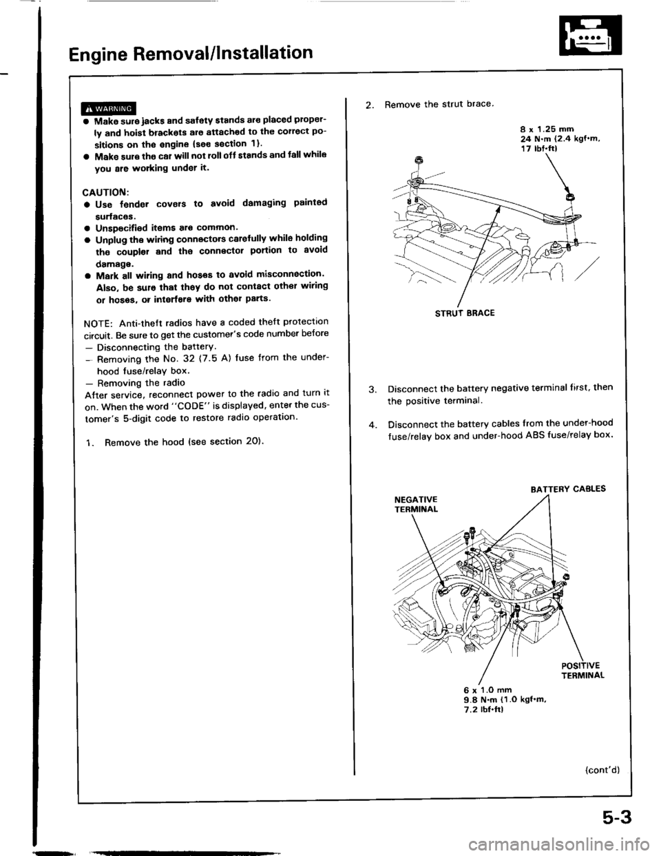
2. Remove the strut brace
8 x 1.25 mm24 N.m (2.4 kgf.m,17 rbt.ft)
Disconnect the battery negative terminal lirst. then
the positive terminal.
Disconnect the battery cables from the undel-hood
fuse/relay box and under-hood ABS fuse/relay box.
6 x l.O mm9.8 N.m (1 .O kgf'm,7.2 rbl.ftl
{cont'd)
STRUT ERACE
BATTERY CABLES
5-3
Page 116 of 1413

Cylinder Head
Removal
Engine removal is not required or this procedure.
CAUTION: To avoid damaging tho cylinder head, wail
u[tilths.nginc coolant tsmperaturo drops bolow 100"F(38'Cl bafore loos6ning tho retaining bolts.
NOTE;
. Inspect the timing belt before removing the cylinder
head.
Turn the crankshaft pulley so that the No. 1 piston is
at top dead center (TDc) {page 6-51).
Mark all emissions hoses betore disconnecting them.
Anti-theft radios have a coded theft protection circuit.
Be sure to get the customer's code number before- Disconnecting the battery.- Removing the No.32 (7.5 A) fuse trom the under-
hood fuse/relay box.- Removing the radio.
After service, reconnect power to the radio 8nd turn it
on.
When the word "CODE" is displaved. enter the cus-
tomer's 5-digit code to restore radio operation,
Disconnect the negative terminal from the battery.
Drain the engine coolant (see page 10-5).
. Remove the radiator cap to speed draining.
Relieve fuel pressure (see section 111.
l@ Do not 3moke whilo working on fuel
a
a
'1.
systgm. ko6p opon tlamo ot Spark away trom work
aroa. Drain fugl only into an approved containsr,
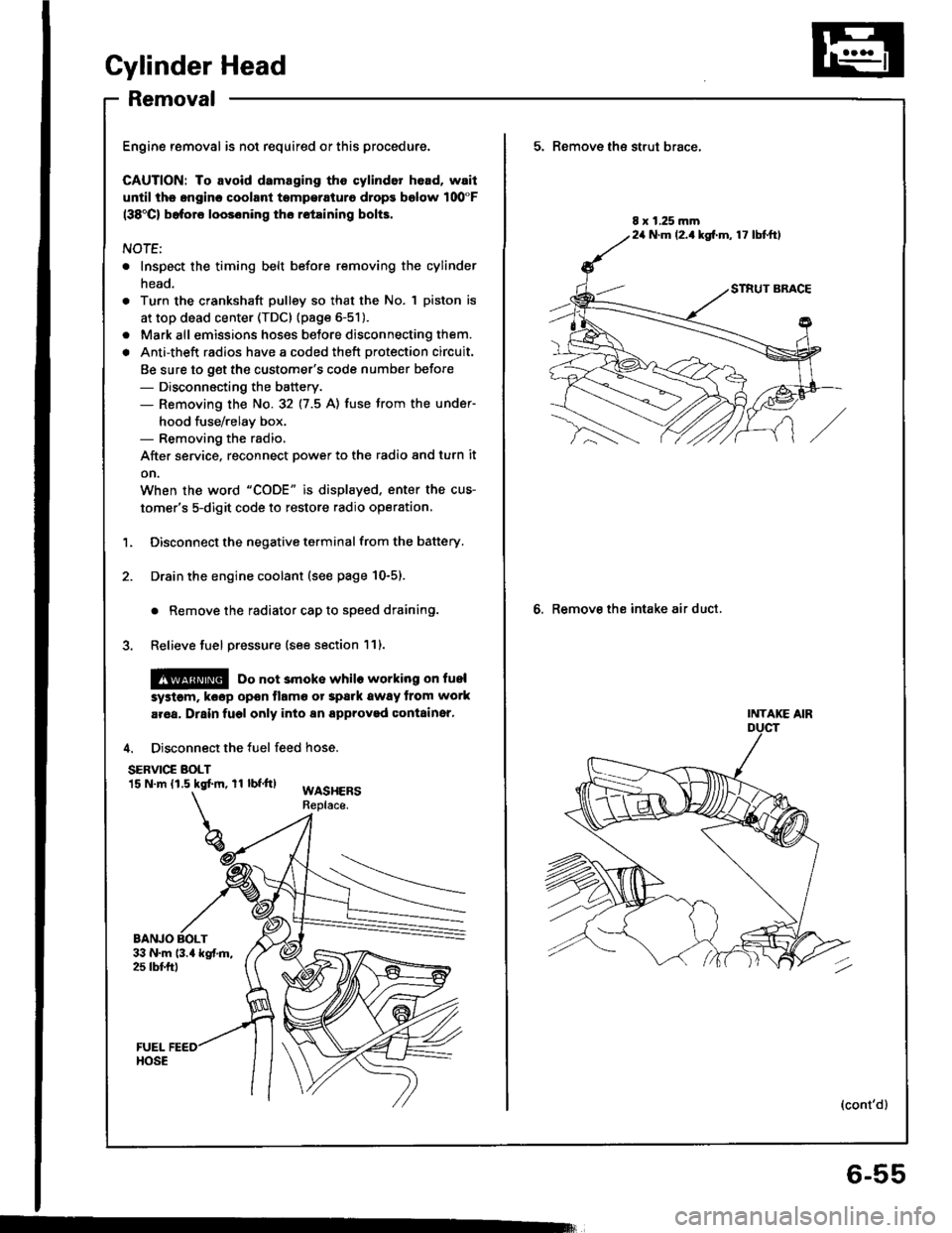
4. Disconnect the fuel feed hose.
SERVIC€ BOLT15 N.m (1.5 kgtm, rl bf.tt)WASHERSReplace.
BANJO BOLT
5. Remove th€ strut brace,
6. Remove the intake air duct.
8 x 1.25 mm24 N.m (2.1kg[.m, 17 lbtftl
INTAKE AIR
(cont'd)
6-55
Page 653 of 1413

Steering Gearbox
Removal (cont'dl
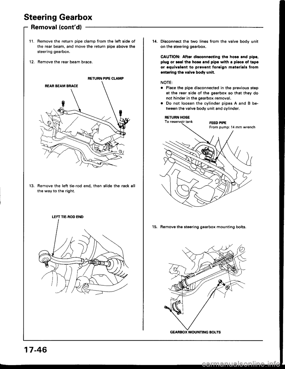
Remove the return pipe clamp from the left side of
the rear beam. and move the return piDe above the
steering gearbox.
Remove the rear beam brace.
Remove the left tie-rod end, then slide the rack
the way to the right.
11.
12.
RETURN PIPE CLAMP
13.
I.TFT TIE-ROD END
14. Disconnect the two lines from th€ valve bodv unit
on the steering gea.box.
CAUTION: Aftor dkconnccting tho ho3o and pip.,
plug or r.d thc ho3. rnd pipc whh I pioco of tapo
or .quivll.nt to prcvont torcign m!tori!|3 f.om
ritrdng thc vdv. body unit.
NOTE:
. Place the pipe disconnected in the previous step
at the rear side of the gearbox so that they do
not hinder in the gearbox removal.
. Do not loosen the cylinder pipes A and B be-
tween the valve body unit and cylinder,
RETUR]T HOSE
15. Remove the steering gearbox mounting bolts.
GEARBOX MOU NNG BOLTS
17-46
Page 671 of 1413

Steering Gearbox
Installation (cont'd)
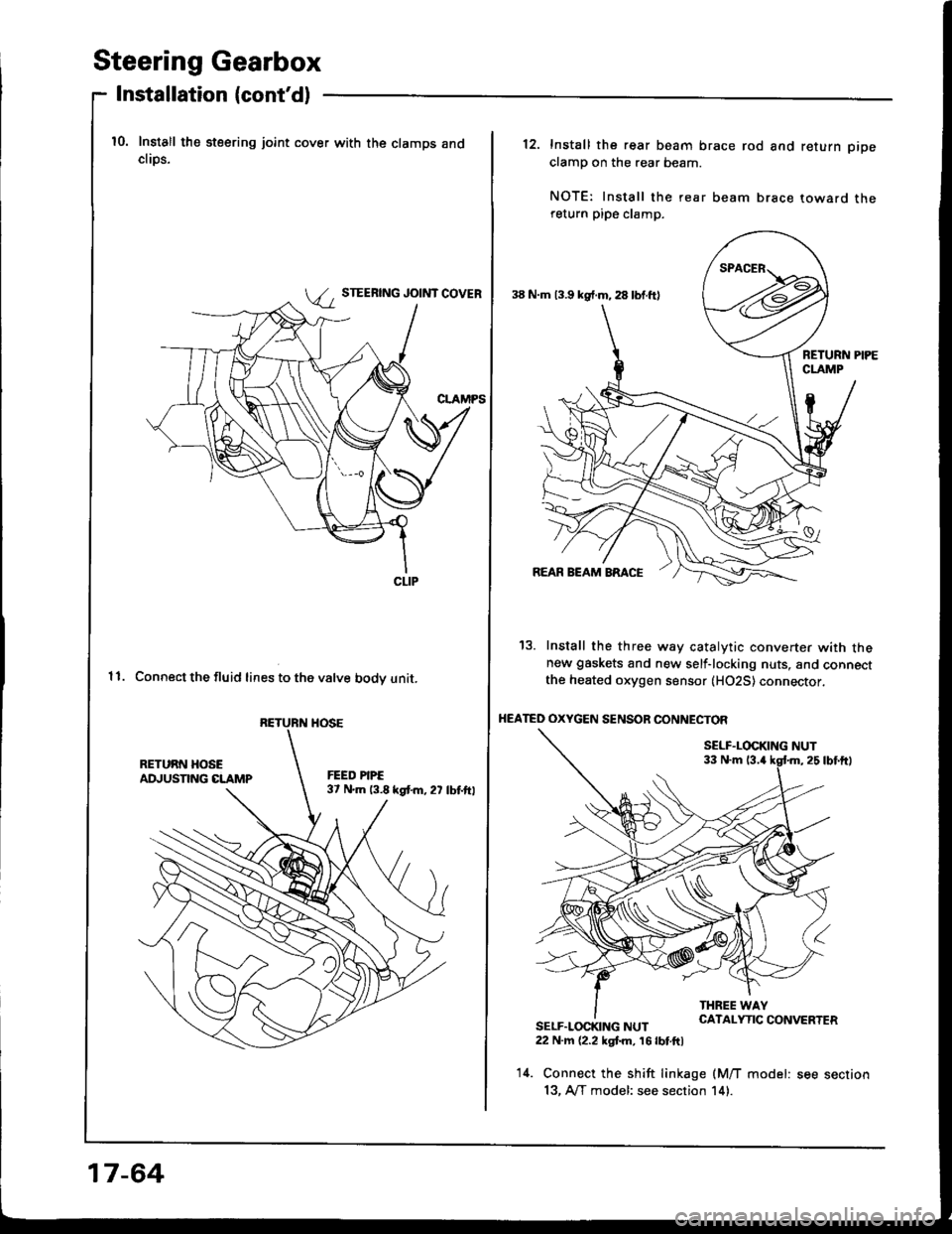
10. Install the steering joint cover with the clamps andcliDs.
STEERING JOINT COVER
11. Connect the fluid lines to the valve bodv unit.
CLIP
RETURN HOSE
17-64
38 N.m 13.9 kg{.m, 28 lbf.ft)
12. Install the rear beam brace rod and return pipe
clamp on the rear beam.
NOTE: Install the rear beam brace toward thereturn pipe clamp.
13. Install the three way catalytic converter with thenew gaskets and new self-locking nuts, and connectthe heated oxygen sensor (H02S) connector,
HEATED OXYGEN SENSOR CONNECTOF
SELF.LOCKING NUT33 N.m 13.4
SELF.LOCKING NUT22 N.m (2.2 kgt m, 16 lbt.ftl
14. Connect the shift linkage (M/T model: see section
13, A/T model: see section 14).