cruise control HONDA INTEGRA 1994 4.G Workshop Manual
[x] Cancel search | Manufacturer: HONDA, Model Year: 1994, Model line: INTEGRA, Model: HONDA INTEGRA 1994 4.GPages: 1413, PDF Size: 37.94 MB
Page 40 of 1413
Lubrication Points
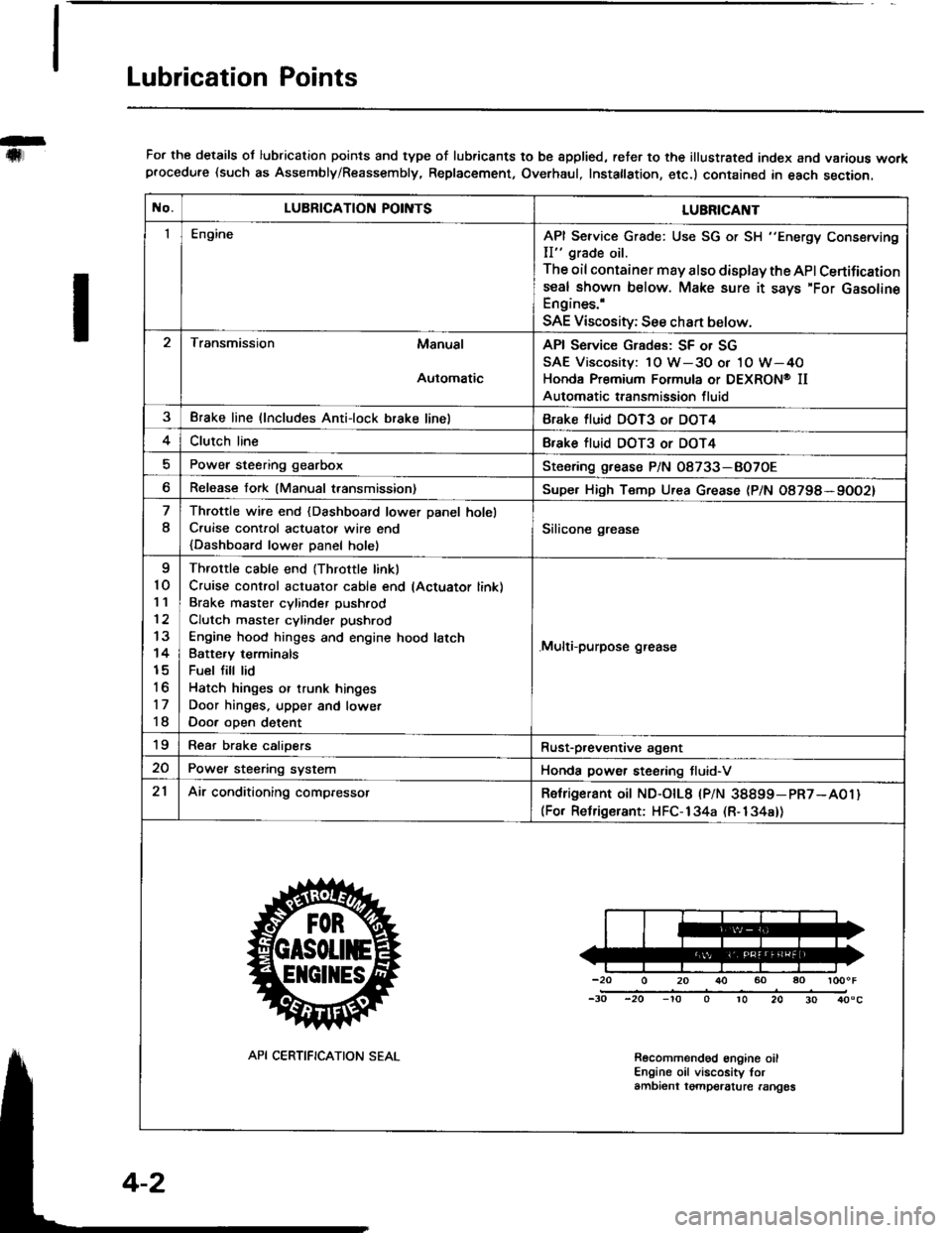
For the details ol lubrication points and type of lubricants to be spplied, reter to the illustrated index and various workprocedure (such as Assembly/Reassembly, Replacement, Overhaul, Instatlation, etc.) contained in each section.
No.LUBRICATION POII\ITSLUBRICAI\IT
IEngineAPI Service Grade: Use SG or SH "Energy Conserving
II" grade oil.
The oil container may also display the API Certifications€al shown below. Make sure it says'For GasolineEngines.'
SAE Viscosity; See chan below.
Transmission Manual
Automatic
API Service Grades: SF or SG
SAE Viscosity: 1O W-3O or 1O W-4O
Honda Premium Formula or DEXRON@ II
Automatic transmission fluid
3Brake line (lncludes Anti-lock brake linelBrake fluid DOT3 or DOT4
4Clutch lineBfake tluid DOT3 or DOT4
Power steering gearboxSteoring grease P/N 08733-BO7OE
Release fork (Manual transmission)Supe. High Temp Urea Grease (P/N O8798*9OO2)
8
Throttle wire end {Dashboard lower Danel holel
C.uise cont.ol actuatot wire end
{Dashboard lower Danel holel
Silicone grease
I
10'I '�l
12
13
14
15
to
17
18
Throttle cable end (Throttle linkl
Cruise control actuator cable end lActuator link)
Brake master cvlinder Dushrod
Clutch master cylinder pushrod
Engine hood hinges and engine hood latch
Batte.v terminals
Fuel fill lid
Hatch hinges or trunk hinges
Door hinges. upper and lowet
Door oDen detent
.Multi-purpose grease
19Rear brake calioersRust-p,eventive agant
20Power steering systemHonda power steering tluid-V
21Air conditioning compressorRetrigerant oit ND-otL8 |PlN 38899-pR7-A01)(For Relrigerant: HFC-134a (R-134a))
-20 0 20 r}() 60 ao loooF
-30 -20 -'to o 10 20 30 40"c
Recolnmendod engine oilEngine oil viscosity torambient tgmpelalure rangos
API CERTIFICATION SEAL
Page 50 of 1413
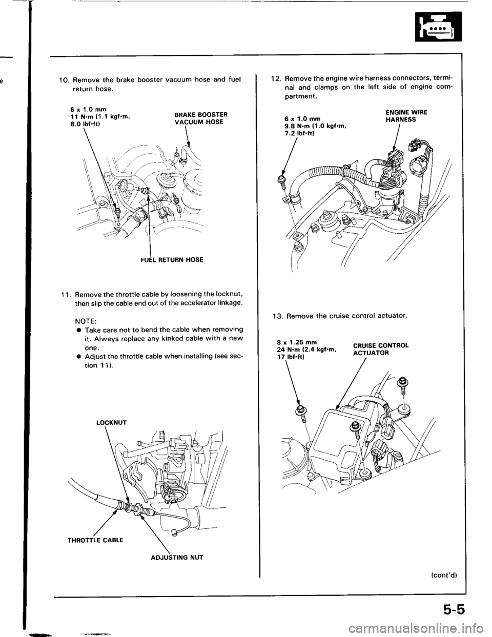
1O. Remove the brake booster vacuum hose and fuel
return hose.
6 x 1.O mm11 N.m {1.1 kgl'm,8.O rbt.ltl
BRAKE BOOSTERVACUUM HOSE
't 1.
BETURN HOSE
Remove the throttle cable by loosening the locknut.
then slip the cable end out of the accelerator linkage.
NOTE:
a Take care not to bend the cable when removing
it. Always replace any kinked cable with a new
one,
a Adjust the throttle cable when installing (see sec-
tion 1 1).
LOCKNUT
AOJUSTING NUT
5-5
't2.Remove the engine wire harness connectors, termi-
nal and clamps on the left side ot engine com-
oartment.
6 x 1.0 mm9.8 N.m {1 .O kgf.m,7.2 tbt.ftl
ENGINE WIREHABNESS
13. Remove the cruise control actualor.
CRUISE CONTROLACTUATOR
8 x 1.25 mm24 N.m (2,4 kgl.m,17 lbf.Irl
Page 73 of 1413
Timing Belt
Removal
I
NOTE:
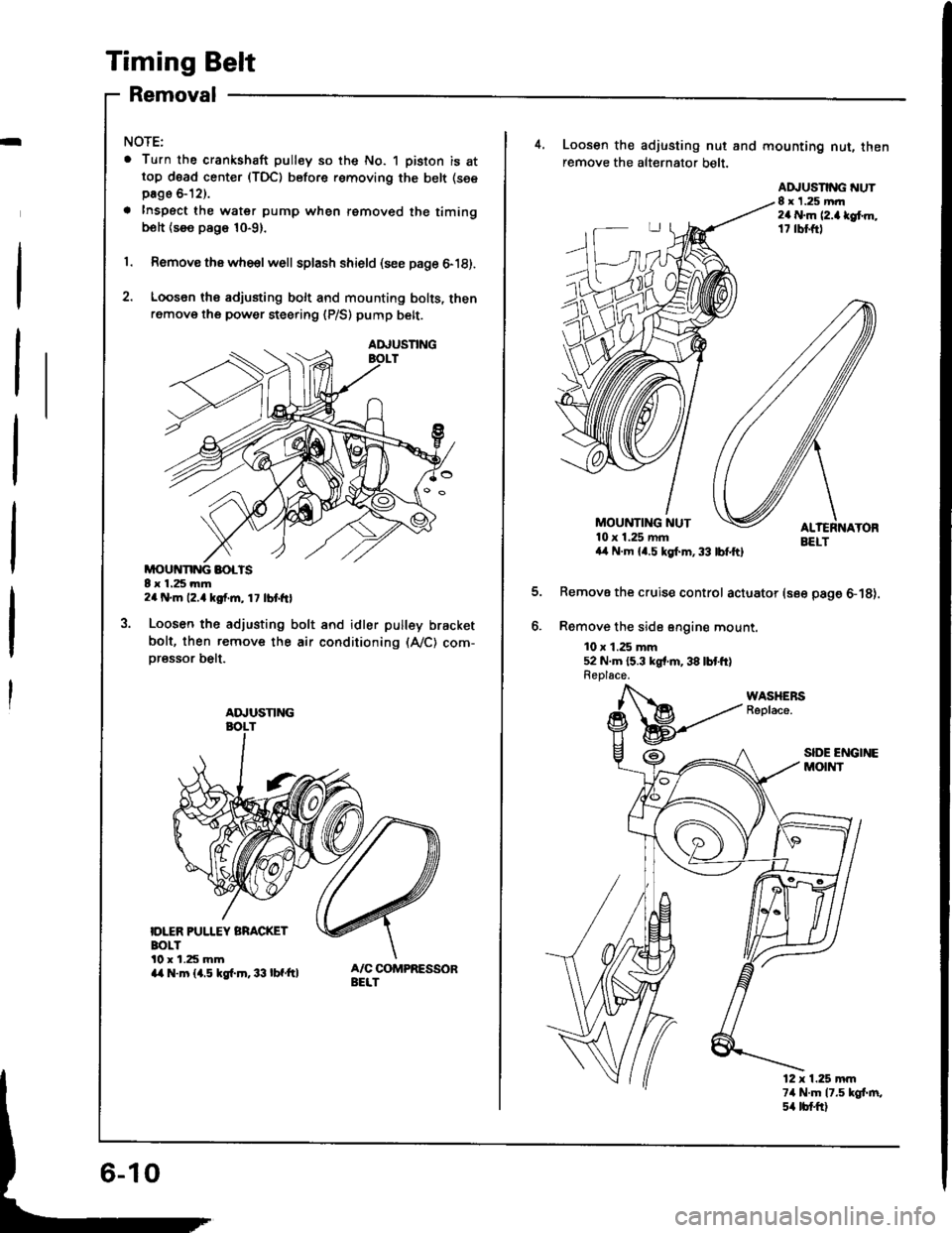
. Turn the crankshaft pulley so the No. 1 piston is attop d6ad center (TDC) before removing the belt (see
page &12).
a Inspect the water pump when removed the timingbolt {see page 10-9}.
1. Remove thawhe€lwell splash shield (see page 6-18).
2. Loosen ths adjusting bolt and mounting bolts, thenremove the power steering {P/S) pump belt.
MOUivNNG BOLTS8 x 1.25 mm2a N.m 12.4 kgf.m, 1 7 lbt frl
Loosen the adjusting bolt and idler pulley bracket
bolt, then remove the air conditioning (A,/C) com-
oressor belt.
IDLER PUI.IEY BRACKETBOLTl0 r 1.25 mma/a N.m {1.5 kgf.m.33 lbf'ft}
AA,USNNG
ADJUSTING
4, Loosen the adjusting nut and mounting nut, thenremove the alt€rnator belt.
EELTa,l N.m {4.5 kgl.m,33 lbfftl
Remove the cruise control actuator (see page 6-18).
Remove the sid6 sngine mount.
10 x 1.25 mm52 N.m {5.3 kgr'm,38 lbtft}Replace.
MOUNTING NUT10 x 1.25 mm
ADJUSNNG NUT8 x 1.25 mrr2a N.m l2.a lef.m,17 rbl.ftl
12 x 1.25 mm74 N.m 17.5 kgt m,s4 tb{.ftl
Page 80 of 1413
Cylinder Head
Removal (cont'dlI
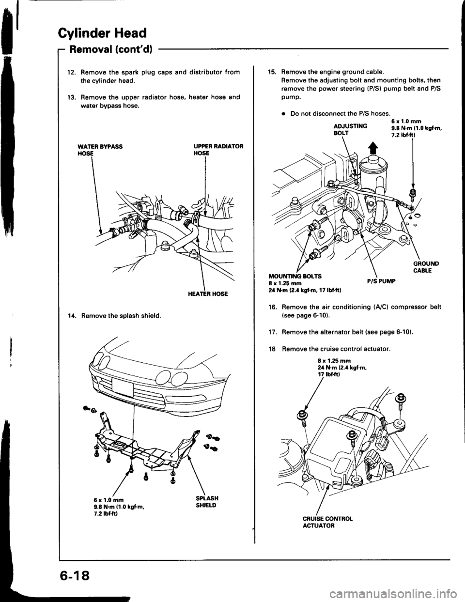
12.R€move the spark plug caps and distributor from
the cvlinder head.
Remove the upper radiator hose, heater hose and
water bypass hose.
UPPER RAI'IAYOR
14. Remove th6 solash shield.
WATER BYPASS
9.8 N.m {1.0 kgt m.t.2 tbr.frt
sHtEut
15. Remove the engine ground cable.
Remove the adjusting bolt and mounting bolts, then
remove the power steering (P/S) pump belt 8nd P/S
pump.
. Do not disconnect the P/S hoses.
6x1.0mmADJUSTINGBOLT9.8 N.m 11.0 tgfm,7.2 tbf.ftl
8 x 1.25 mm24 .m (2.akstm, 17lbf.ftl
P/S PUMP
Remov€ the air conditioning (Ay'Cl compressor(see pags 6-10).
R€move the alternator belt (see page 6-10).
Ramove the cruise control actuator.
8 x 1.25 mm2a N.m 12.4 kgt m,
belt
17.
t8
ACTUATOR
Page 110 of 1413
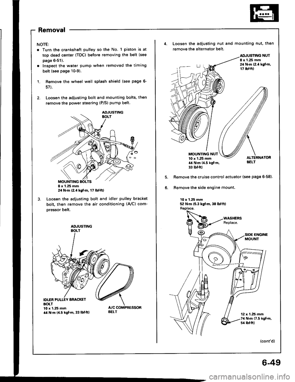
Removal
NOTE:
. Turn the crankshaft pulley so the No. 1 piston is at
top dead center {TDC) before removing the belt (see
page 6-51).
. Inspect the water pump when removed the timing
belt {see page 10-9).
Remove the wheel well splash shield (see page 6-
57 ).
Loosen the adiusting bolt and mounting bolts, then
remove the power steering (P/S) pump belt.
I x 1.25 mm2a N.m l2.a kgt.m, 17 lbt ttl
Loosen the adjusting bolt and idler pulley bracket
bolt, then remove the air conditioning (Ay'C) com-
oresso. belt.
D1INBOLT10 x 1.25 mmira N.m (4.5 kgf.m, 33 lbf'ttl
AOJUSTING
ADJUSNNG
BELT
4. Loosen the adiusting nut and mounting nut, then
remove the alternator belt.
NUTI x 1.25 mm24 N.m {2.a lgf.rn,17 tbf.ftl
MOUNTING NUT10 x 1.25 mm4,t N.m lia.5 kgl.m,33 tbt ftl
Remove the cruise control actuator (see page G58).
Bemove the side engine mount.
10 x 1.25 mm52 N.m 15.3 kgt m, 38 lbtftl
CNGINCMOUNT
12 x 1.25 mm74 N.m (7.5 kgt m,s4 lbf.trl
(cont'd)
6-49
Page 119 of 1413
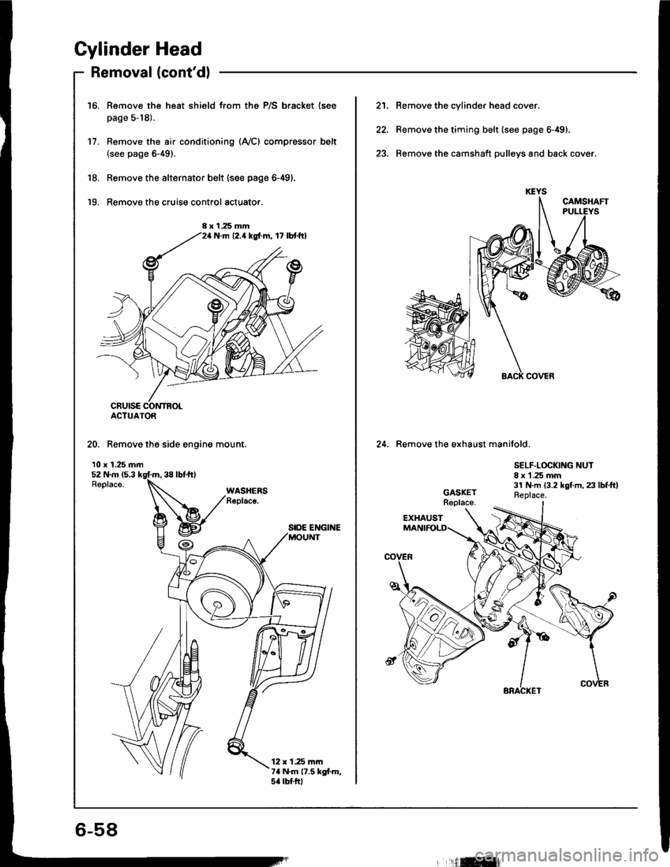
Cylinder Head
Removal (cont'dl
Remove the heat shield from the P/S bracket (see
page 5-18).
Remove the air conditioning (Ay'Cl compressor belt(see page 6-49).
Remove the alternator belt {s€e page 6-49).
Remove the cruise control actuato..
16.
17.
'18.
'19.
ACTUATOR
20. Remove the side engine mount.
10 x 1.25 mm
SIDE ENGINE
12 x 1.25 mrn7a N.m 17.5 kgl.m,5a rbtftl
8 x 1.25 mmN.m 12.4 kgf.m, 17 lbtftl
21. Remove the cylinder head cover.
22. Remove the timing belt (see page 6-49).
23. Remove the camshaft pulleys and back cover.
24. Remove the exhaust manifold.
SELF.LOCKING NUT8 x 1 .25 mm31 N.m {3.2 kgt m, 23 lbf.ftlReplace.
6-58
'ilffi{
Page 631 of 1413
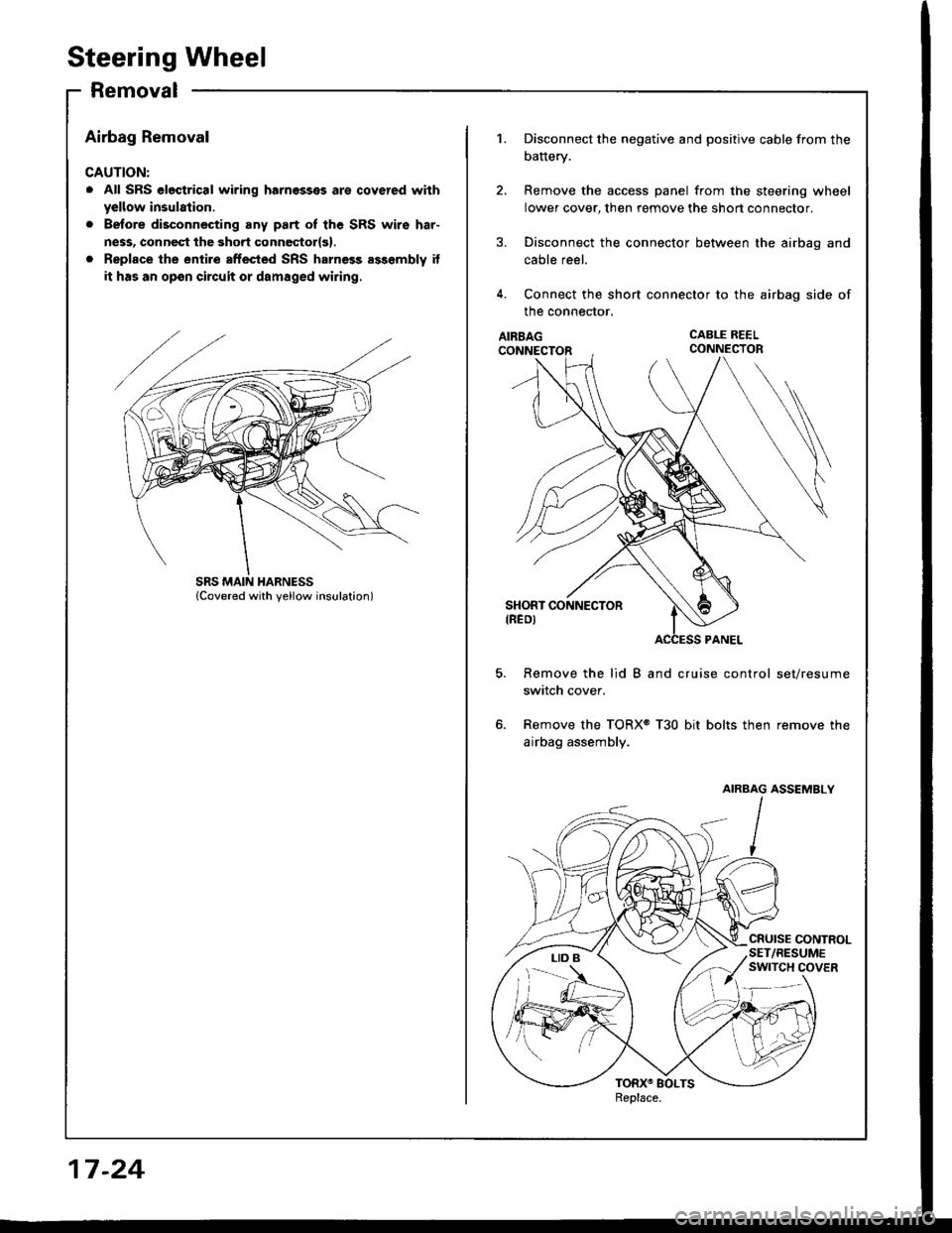
Steering Wheel
Removal
Airbag Removal
CAUTION:
. All SRS electrical wiring harnosses are covered with
yellow insulation.
. Before disconnecting any part oI the SRS wiro har-
ness, connect the 3hort connector{g}.
. Replace the entire sffected SRS harness assembly it
it has an opon circuit or damaged wiring.
17-24
1.
AIRBAGCONNECTOR
CABLE REELCONNECTOR
Disconnect the negative and positive cable from the
battery.
Remove the access panel from the steering wheel
lower cover, then remove the shon connector.
Disconnect the connector between the airbag and
cable reel.
Connect the shon connector to the airbag side of
the connector.
Remove the lid B and cruise control set/resume
switch cover.
Remove the TORX@ T30 bit bolts then remove the
airbag assembly.
AIRBAG ASSEMBLY
Page 632 of 1413
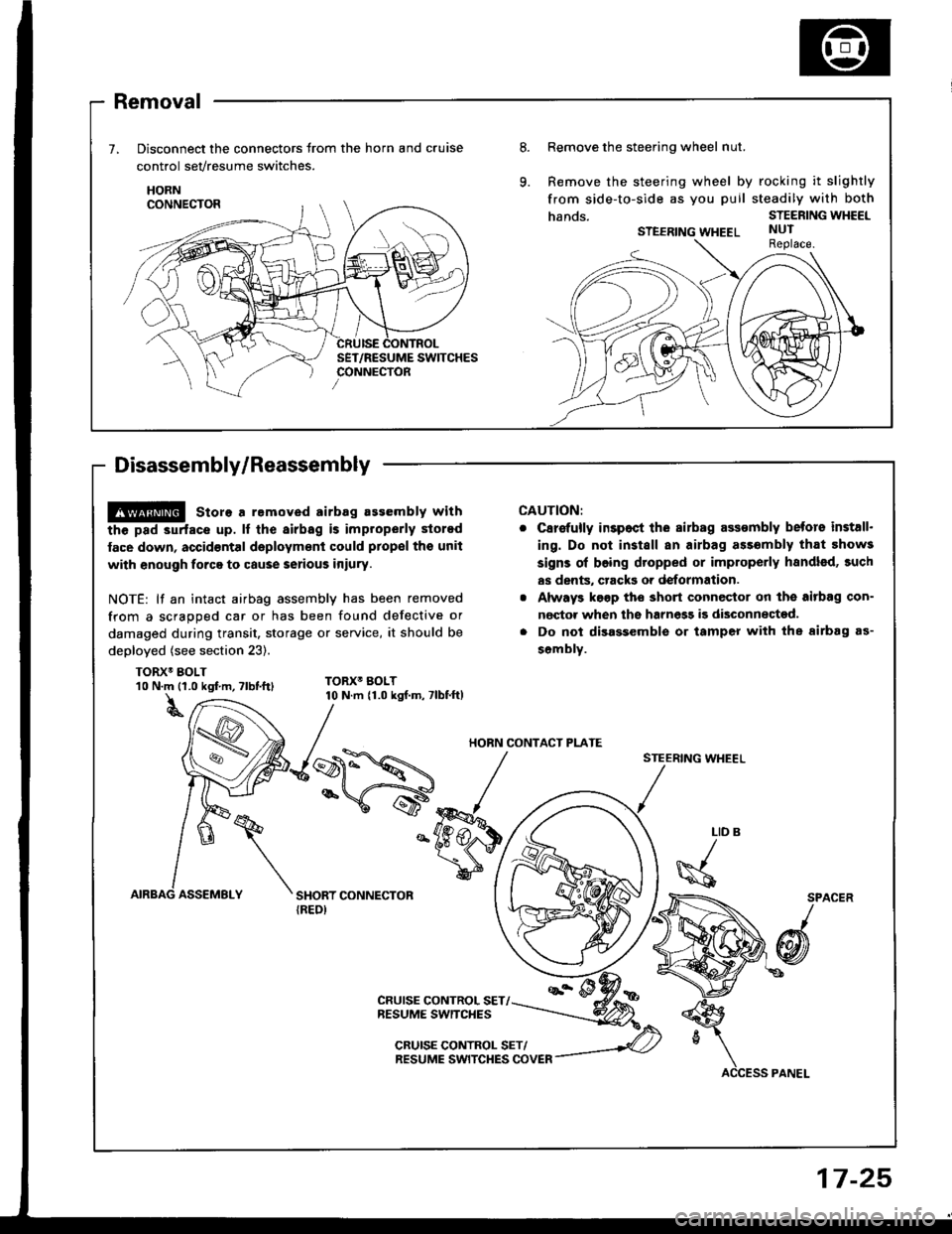
Removal
Disconnect the connectors trom the horn and cruise
control sevresume switches.
HORN
Disassembly/Reassembly
8.Remove the steering wheel nut.
Remove the steering wheel by rocking it slightly
from side-to-side as you puil steadily with both
hands.STEERING WHEEL
STEERING WHEELNUTReplace.
@ store a removed airbag assembly with
the pad 3urfacs up. lf the airbag is improperly stored
face down, accid€ntal daployment could prop€l tho unit
with enough forca to cause serious iniury.
NOTE: lf an intact airbag assembly has been removed
from a scragoed car or has been found defective or
damaged during transit. storage or service, it should be
deployed (see section 23).
TORX6 BOLT
CAUTION:
C8r€{ully inspoct ihe sirbag assombly betors install.
ing. Do not install an airbag ass6mbly that 5how3
signs ol boing dtopped or improperly handled, such
as dents, crack3 or deformation.
Always k€gp tho short connector on the aitbag con-
nector when ths harnegg i9 disconnected.
Do not disassemble or tamper with the airbag as-
sombly.
STEERING WHEEL
10 N.m {1.0 kgf m, Tlbt.ttl
t
TORX6 BOLT10 N.m {1.0 kgf.m, 7lbf.ft)
LID
\s
SPACER
/
@
CRUISE CONTROL SET/NESUME SWITCHES
CRUISE CONTROL SET/RESUME SWITCHES COVER
HORN CONTACT PI-ATE
17-25
Page 633 of 1413
Steering Wheel
Installation
Airbag installation
CAUTION:
. B€fore inrtalling the stooring wheel, align tho front
who6l3 etraight ahead.
. Bo sure to install the harness wires so that thGy are
not pinched or intorfsring with othor car parts.
. Do not roplace thc original stsoring wheel with any
othor design. since it will maks it impo$ibla to prop-
erly install the airbag. {Only use genuine HONDA
replscomont parts)
. After rols3embly. confirm thai the whoels are still
straight ahoad 8nd that steoring wheel spoke anglo
is correct. lf minor spoke anglo adiustment is noc€s-
srry, do so qnly by adlustment ol th€ tie-rods, not byromoving and repositioning the steering wh€€|.
@ contirm ihat the airbag assombly is
socurely attachsd to the stooring wheel; oth€rwise,
scvoro porsonal iniury could r€sult during airbag
doploym6nt.
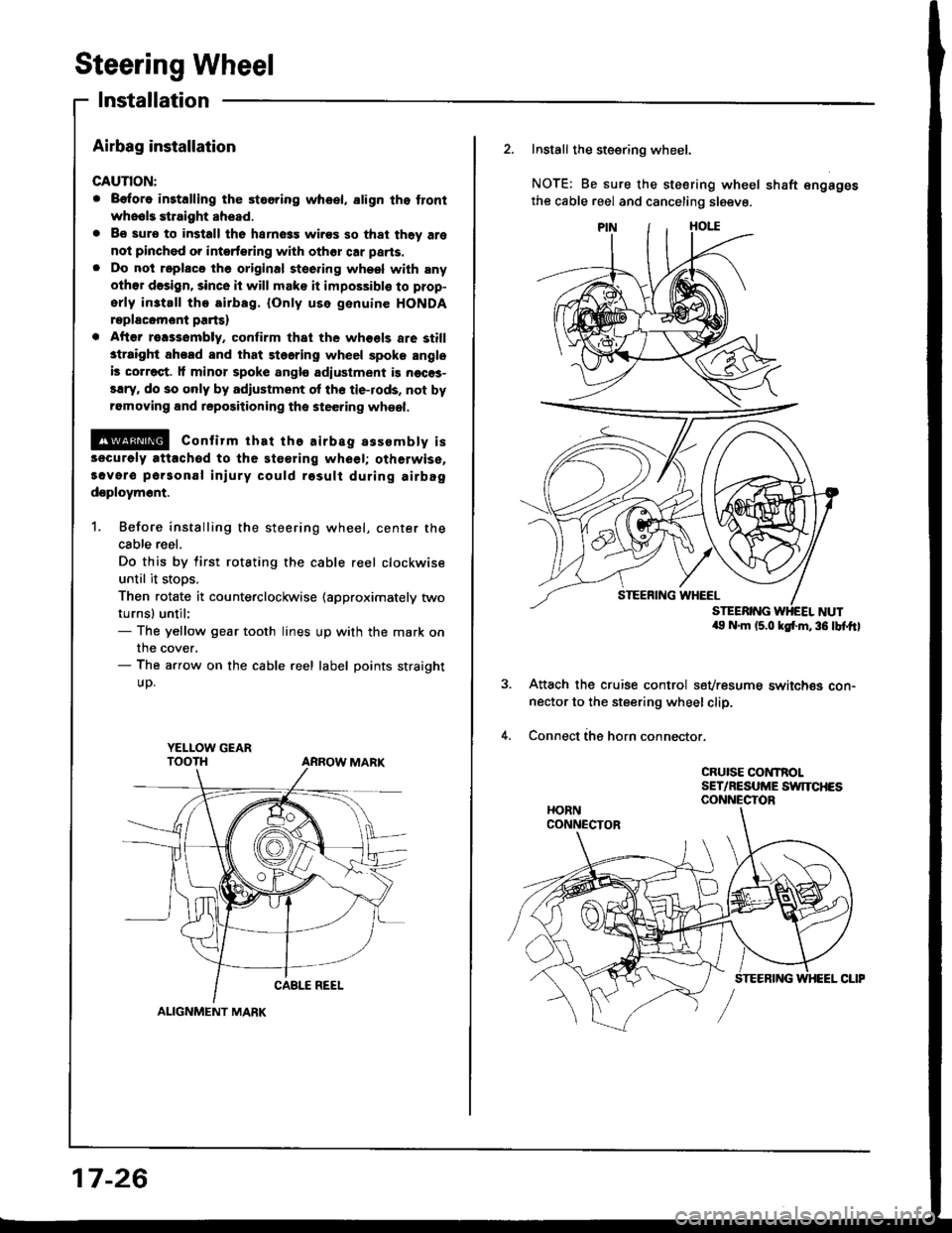
1. Before installing the steering wheel, center the
cable reel.
Do this by tirst rotating the cable reel clockwise
until it stoos.
Then rotate it counterclockwise (approximately two
turnsl until:- The yellow gear tooth lines up with the mark on
the cover.- The arrow on the cable reel label points straight
UD.
YELI-OW GEAR
ALIGNMENT MARK
17-26
2. Install the steering wheel.
NOTE: Be sure the steering wheel shaft engages
the cable reel and canceling sleeve.
a9 N.m (5.0 ksf'm,36 lbf.ftl
Attach the cruise control sevresume switch€s con-nector to the steering wheel clip.
Connect ihe horn connector.
CRUISE CONTROLSET/NESUME SWITCHESCONNECTOR
Page 634 of 1413
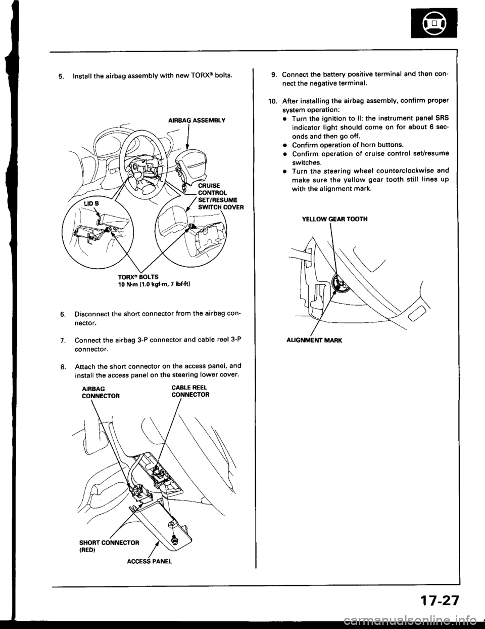
5. Install the airbag assembly with new TORXo bolts.
TORXO BOLTS10 N.m {1.0 kgf'm.7 lbf ftl
Disconnect the short connector trom the airbag con-
nector.
Connect the airbag 3-P connector and cable reel 3-P
connector.
Attach the short connector on the access panel. and
install the access panel on the steering lower cover.
CABLE REEI-CONNECTOR
7.
YELLOW GEAR TOOTH
ALIGNMENT MARK
10.
Connect the battery positive terminal and th€n con-
nect the nsgative terminal.
After installing the sirbag assembly, confirm proper
system opera(on:
. Turn the ignition to ll: the instrum€nt pan6l SRS
indicator light should come on for about 6 sec-
onds and then go off,
. Confirm operation of horn buttons.
. Confirm oDeration of cruise control sevresume
switches.
a Turn the steering wheel countetclockwise and
make su.e the yellow gear tooth still lines up
with the alignment mark.
17-27