distributor HONDA INTEGRA 1994 4.G Workshop Manual
[x] Cancel search | Manufacturer: HONDA, Model Year: 1994, Model line: INTEGRA, Model: HONDA INTEGRA 1994 4.GPages: 1413, PDF Size: 37.94 MB
Page 68 of 1413
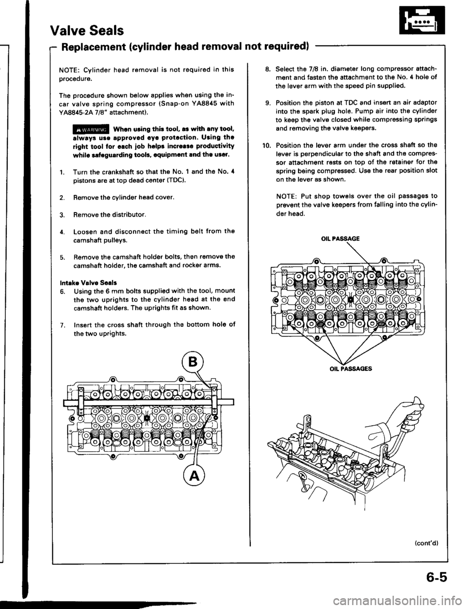
Valve Seals
Replacement (cylinder head removal not requiredl
NOTE: Cylinder head removal is not required in this
procedure.
The procodure shown below applies when using the in-
car valve spring compressor (Snap-on YA8845 with
Y AAA$-2A 718" attachment).
@@ whcn u3ing this tool, a: with any tool,
always u!€ agproved cyr Protcction. Using th.
right tool for cach iob hclps incraa3. produstivity
whilo 3ltrgu8rding tool!, cquipmcnt lnd the u3c1'
1. Turn the crankshaft so that the No. I and the No' 4
pistons are at top d€ad center (TDC).
2. Remove the cylinder head cover.
3. Remove the distributor.
4. Loosen and disconnect the timing belt from the
c8mshaft pulleys.
5. Remove the camshaft holde, bolts, then r€move the
camshaft holder, the camshaft and rocksr arms.
lntakc V!lv6 Sclls
6. Using the 6 mm bolts supplied with the tool, mount
the two up.ights to the cylinder head 8t the end
camshaft holde.s. The uprights fit as shown.
7. Insort the cross shaft through the bottom hole ot
the two up.ights.
6-5
OIL PASSAGE
OIL PASSAGES
Select the 7E in. diameter long compressor attach-
ment and fasten the attachment to the No. 4 hole of
the lever arm with the speed pin supplied.
Position the piston at TDC and insert an air adaptor
into th€ spark plug hole. Pump air into the cylinder
to keep the valv€ closed while cgmpressing springs
and removing the valve keepers.
Position the lever arm under the cross shaft so the
lever is psrpendicular to the shEft and ths compres-
sor attachment rests on toD of the rstainer for th€
spring being compressed. Use the rear position slot
on the lever as shown.
NOTE: Put shop towels over the oil passag€s to
prevent the valve keepers from falling into the cylin-
der h€ad.
(cont'd)
Page 80 of 1413
Cylinder Head
Removal (cont'dlI
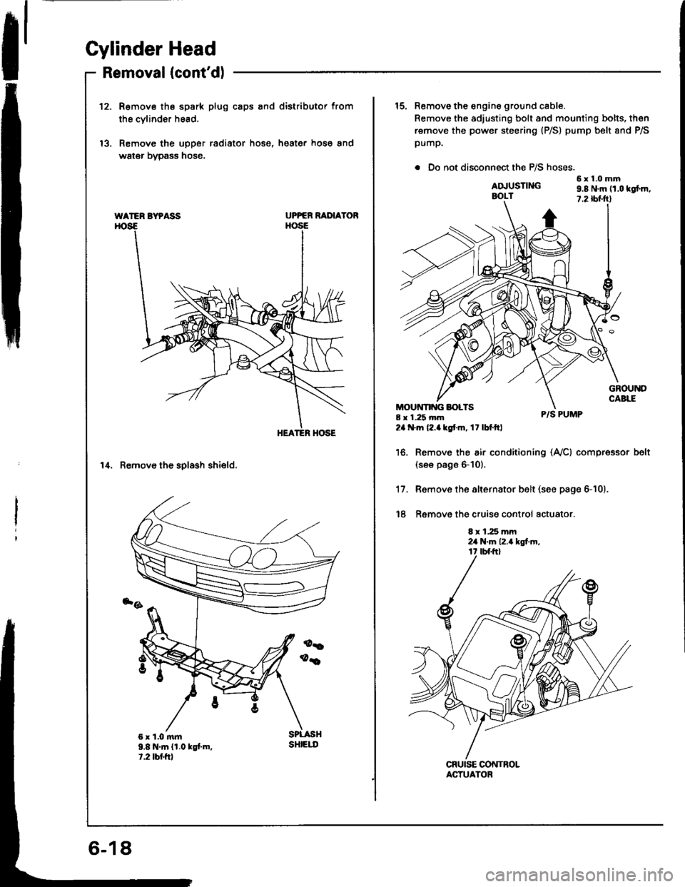
12.R€move the spark plug caps and distributor from
the cvlinder head.
Remove the upper radiator hose, heater hose and
water bypass hose.
UPPER RAI'IAYOR
14. Remove th6 solash shield.
WATER BYPASS
9.8 N.m {1.0 kgt m.t.2 tbr.frt
sHtEut
15. Remove the engine ground cable.
Remove the adjusting bolt and mounting bolts, then
remove the power steering (P/S) pump belt 8nd P/S
pump.
. Do not disconnect the P/S hoses.
6x1.0mmADJUSTINGBOLT9.8 N.m 11.0 tgfm,7.2 tbf.ftl
8 x 1.25 mm24 .m (2.akstm, 17lbf.ftl
P/S PUMP
Remov€ the air conditioning (Ay'Cl compressor(see pags 6-10).
R€move the alternator belt (see page 6-10).
Ramove the cruise control actuator.
8 x 1.25 mm2a N.m 12.4 kgt m,
belt
17.
t8
ACTUATOR
Page 118 of 1413
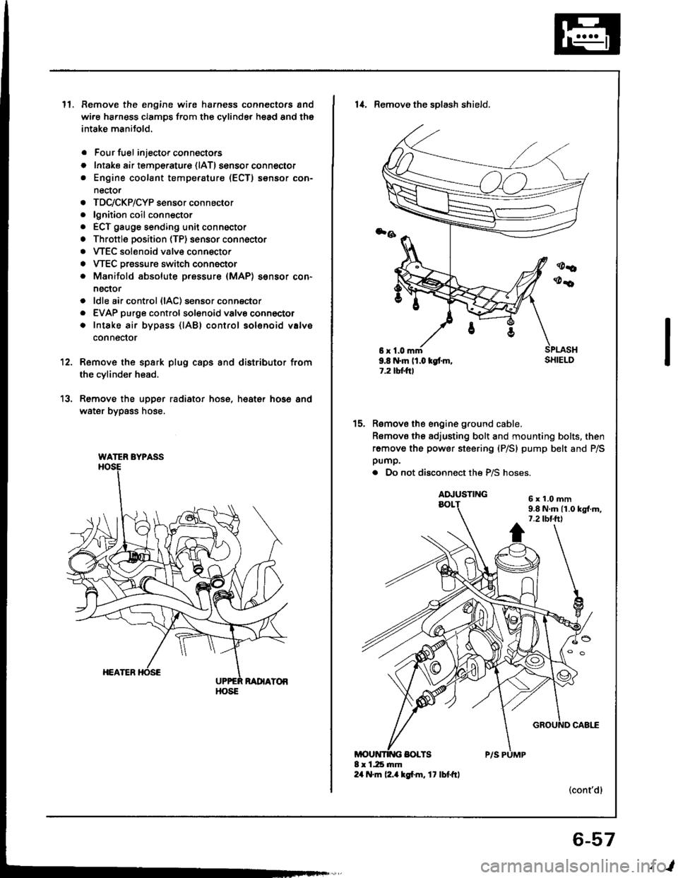
ll.Remove the engine wire harness connectors and
wi.e ha.ness clamps from the cylinder head and the
intake manitold.
Four fuel injector connectors
Intake air tempe.ature {lAT) sensor connector
Engine coolant temperature (ECT) sensor con-
nector
TDC/CKP/CYP sensor connector
lgnition coil conn€ctor
ECT gauge sending unit connector
Throttle position (TP) sensor connector
VTEC solenoid valve connector
VTEC Dressure switch connector
Manifold absolute pressure (MAP) sensor con-
nector
ldle air control {lAC) sensor connector
EVAP purge controlsol€noid valvo connector
Intake air bypass {lABl control solenoid valve
conneclor
a
o
a
o
a
a
a
a
a
a
a
a
a
12.
13.
Remove the spsrk plug caps and distributor from
the cylinder head.
Remove the upper radiator hose, heat€r hose and
water bypass hose.
WATER BYPASS
HOSE
6r1.0mm9.8 N.m (1.0 kgt m,1.2 tbtftl
14. Remove the sDlash shield.
Remove the engine ground cable.
Romovo the adjusting bolt and mounting bolts, then
remove the power steering (P/S) pump belt and P/Spump.
. Do not disconnect the P/S hoses.
(cont'dl
15.
6x1.0mm9.8 N.m 11.0 kgl.m,7.2 tbt.ttl
6-57
,l
Page 126 of 1413
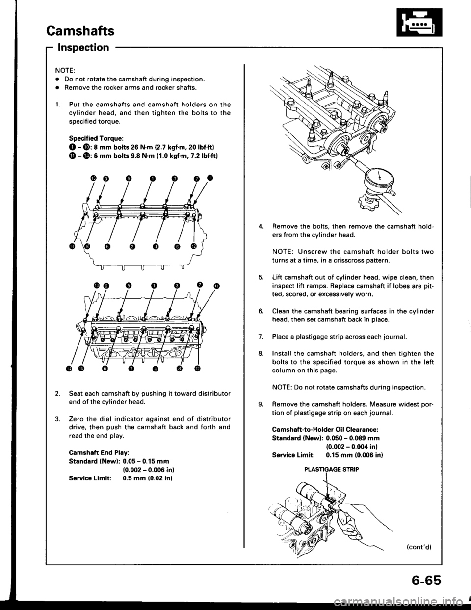
Camshafts
Inspection
4,
5.
9.
1.
Remove the bolts, then remove the camshaft hold-
ers from the cvlinder head.
NOTE: Unscrew the camshaft holder bolts two
turns at a time, in a crisscross pattern.
Lift camshaft out of cylinder head. wipe clean, then
inspect lift ramps. Replace camshaft if lobes are pit-
ted, scored, or excessively worn.
Clean the camshaft bearing surfaces in the cylinder
head. then set camshaft back in place.
Place a plastigage strip across each journal.
Install the camshaft holders, and then tighten the
bolts to the specified torque as shown in the left
column on this page.
NOTE: Do not rotate camshafts during inspection.
Remove the camshaft holders. Measure widest Dor-
tion of plastigage strip on each journal.
Camshaft-to-Holder Oil Clearance:
Standard {New): 0.050 - 0.089 mm
{0.002 - o.Ooil in)
Sswice Limit: 0.15 mm (0.006 in)
(cont'dl
NOTE:
. Do not rotate the camshaft during inspection.
. Remove the rocker arms and rocker shafts.
1. Put the camshafts and camshaft holders on the
cylinder head, and then tighten the bolts to the
soecified torque.
Specified Torque:
O - @: 8 mm bolts 26 N.m {2.7 kgl.m,20 lbt'ftl(D -(D:6 mm bolts 9.8 N.m {1.0 kgt.m, 7.2 lbf'ftl
Seat each camshaft by pushing it toward distributor
end of the cylinder head.
Zero the dial indicator against end of distributor
drive, then push the camshaft back and forth and
read the end play.
Camshaft End Play:
Standard (New): 0.05 - 0.15 mm
10.002 - 0.006 inl
Sawics Limit: 0.5 mm (0.02 inl
oooo@
Page 248 of 1413
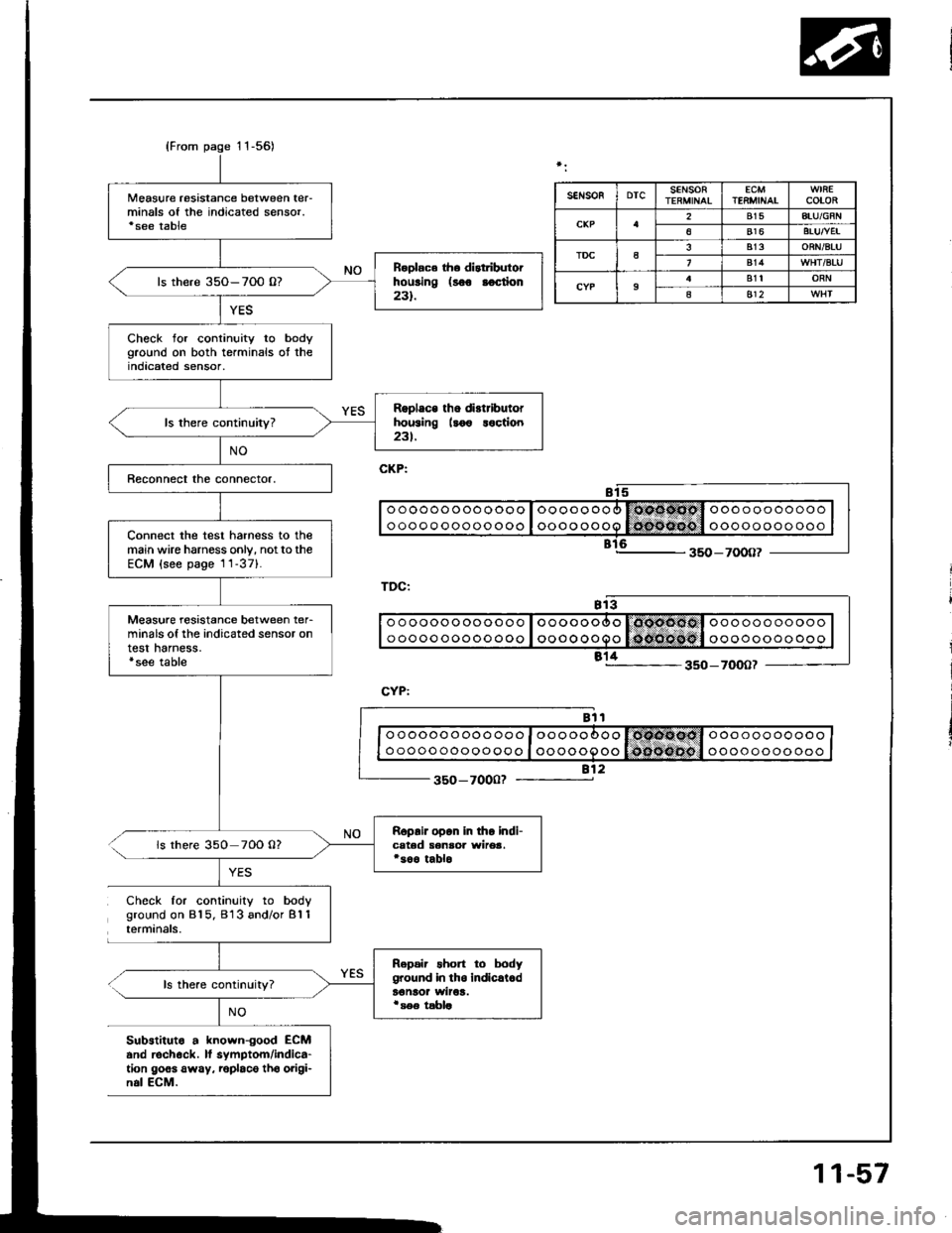
{From page 11-56)
Measure resistance between ter-minals of the indicated sensor.'see table
R.olac6 th. distributorhousing (8oo aoction231.ls there 35O-7O0 0?
Check for continuity to bodyground on both terminals ot theindicated sensor,
Rgplace tho di.tributorhousing llo€ loction23t.
Connect the test harness to themain wire harness only, notto theECM (see page 1 1-371.
Measure resistance between ter-minals of the indicated sensor ontest harness.'see table
Roprir opon in tho indi-cated senaoa wirea.*soo tablols there 350 70O 0?
Repair short to bodyground in tho indicrl.dt€naor wiroa.i s€e tabla
SEIiSOFDTCSENSORECMTENMINAICOLOR
2815ATU/GFN
6816BTUTVEI
TDCa813ORN/BTU
814
9B1tORN
as12
o o ooooo oo ooo o I oooooooo l6coocl o oo ooo ooooo
o oooo ooooo ooo I oooo oooo lo{nofioo't oooooooo ooo
812350-7000?
Check for continuity to bodyground on 815. 813 and/or B'l 1terminals.
ls there continuity?
NO
Substituto a known-good ECMand rechock. lf symptom/indica-tion goes away. roplaco tho origi-n.l ECM.
11-57
Page 1107 of 1413

Electrical
Special Tools
Troubleshooting
Tips and Precautions ................................ 23-3Five-stop Tloubleshooting ..............,...-..-... Z3-sSchematic Symbols ................................_. 23-6wire Color Cod€s ..................................... 23-6Relay and Control Unit Locations
Engine Compartment .........,............ ... --. 23-7Dsshboard and Door ..,,......................... 23-gDashboard and Floor ............................. 23-t OOuaner Panel .....-.....23-12Connector ldentification and WireHarness Routing ........ 23-i 3
Index to Circuits and Systems
Airbag ............... ...-..-... 2g-26sAir Conditioning ....,.. Section 2lAltelnator ......_.............. 23-99Anti-lock Brake Systsm (ABS) Section 19Automatic Transmission Section 14Battery .............. .......... 23-66Chafging System ........... 23-98rCigalstte Lighter .....................-...-......-..-.. Z3-2O4Cfock ................. ..........23-197rcruise Controf .......--..-... 23-242Distributor .................... 23-87Fan Controls ................. 23-1ogFuel and Emissions ... Section 1i*Fuses
Under-dash Fuse/Relay Box ................... 23-48Undor-hood ABS Fuse/Retay Box ............ 23-51Under-hood Fuse/Relay Box,.................. 23-52rGauges
Engine Coolant Temperature {ECT)Gauge ................ ..23-126Fuef cauge ............... 2g-123'Gauge Assembly ....--.23-113Speedometer .....-...,,. 23-114Tachometer .....,.....-.. 23-114Ground Distribution ........ 23-60Heater ,,,........,.... ..... Section 2lrHorn ................. ........... 23-199*fgnition Switch ............. 23-70fgnition Syst6m .......-..-.. 23-A7lgnition Timing .............. 23-89Indicator Lights"A/T Gear Position .............. ................... 23-1 32B1ak6 System ...,..,..-.23-127Engine Oil Pressura .............................. _ 23-1 51Low Fuel ............ ......23-125Malfunction Indicator Lamp {MlL} ...,,. Section I l
tfnteglated Control Unit ...29-144*lnterlock System ...................................... 23-1 3gLights, Exteriol
Back-up Lights ........... 23-179Brake Lights .............. 23-t8ltDaytime Running Lights {Csnada} ........... 23-156Front Palking Lights ............................. 23-1 65Flont Side Marker Lights ....................... 23-165Front Turn Signal Lights ........................ 23-1 65*Hazard Warning Lights .........................- 2g-1A4Headlights ................. 23-t6tLicense Plate Lights .............................. 23-1 69Taillights(Harchback) .......... 23-166
{Sedan) .............. .. 23-167Lights. Inteliol
Cargo Area Light {Hatchback) ...... -.. -.. -... 23-177Ceifing Light ........-..-.23-175
Dash Lights Blightness Controt .............. 23-t70Glove Box Lighr ................................... 23-1 69Spotfighr ............ ....-.23-174Trunk Light (Sedanl ............... .............. - 23.-177*Lighting Sysrem .......-.-... 23-152:Moonroof ,,.,.......,..,,,,,.-.23-211PGM-FI Systom ........ S€crion 11Power Distribution .,.-..--..23-54Power Door Locks .............,,..................... 23-233Power Mirors ..,..,....-...- 23-216Power Relays ...........,..... 23-68Power Windows ............ 29-222*Rear Window Defogger ........,... ..........,..... - 23-20,6Reminder Systems
Key-in Remindel System ....,.............,.... 23-1 50Lights-on Reminder System ................... 23-l 5f*Maintenance Reminder system ..,,.... -.. - -. 23-.1 2gSeat Belt Reminder System ..................- 23-125*Side Markel/Turn Signal/Hazard
Ffasher System .,..,..-.23.-1A4Spark Pfugs .........-...-..... 23-97Starting System ....,,.....-. 23-73*Stereo Sound System ...,.......................,,.. 23-l gg
Supplemental Restraint System {SRS} ......... 23-265Vehicfe Speed Sensor {VSS) .............--..-.... 23-122*Wiper/Washer Systom ...............--.........-..- Zg-254
rRead SRS pi€cautions on Page 23-271 betore workingin these areas.
-+
Page 1182 of 1413
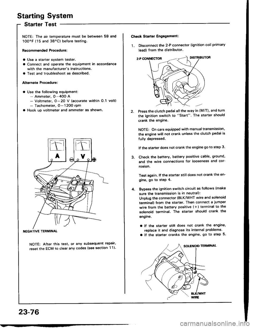
Starting System
Startel Test
NOTE: The air temDerature must be between 59 8nd
10OoF (15 and 38oC) before testing.
Recommendsd Procodure:
a Use a staner svstem tester.
a Connect and operate the equipment in accordance
with the manutacturer's instructions.
a Test and troubleshoot as described.
Altohato Procedure:
a Use the following equipment:- Ammeter. 0-4OO A- Voltmeter, O- 20 V {accurate within 0.1 volt)
- Tachometer, O- 120O rpm
a Hook up voltmeter and ammeter as shown'
NEGATIVE TERMINAL
NOTE: After this test, or any subsequent repair,
reset the ECM to clear any codes (see section 1 1)
23-76
2.
Chock Stan€r Engag6ment:
1. Disconnect the 2-P connector (ignition coil primary
lead) from the distributor.
Press the clutch pedal allthe way in (M/T), and turn
the ignition switch to "Start". The starter should
crank the engine.
NOTE: On cars equipped with manual transmission,
the engine will not crank unless the clutch pedal is
fully depressed.
lf the staner does not crank the engine go to step 3.
Check the baftery, battery positive cable, ground,
and the wire connections for looseness and cor-
rosion,
Test again. lf the starter still does not crank the en-
gine, go to step 4.
Bvpass the ignition switch citcuit as follows {make
sure the transmission is in neutral):
Unplug the connector (BLK/WHT wire and solenoid
terminsl) trom the starter. Then connect a jumper
wire from the battery positive ( + ) terminal to the
solenoid terminal. The starter should crank the
engrne.
a lf the starter still does not crank the engine,
replace it and diagnose its internal problems.
a lf the starter cranks the engine, go to step 5.
J.
4.
Page 1193 of 1413
lgnition System
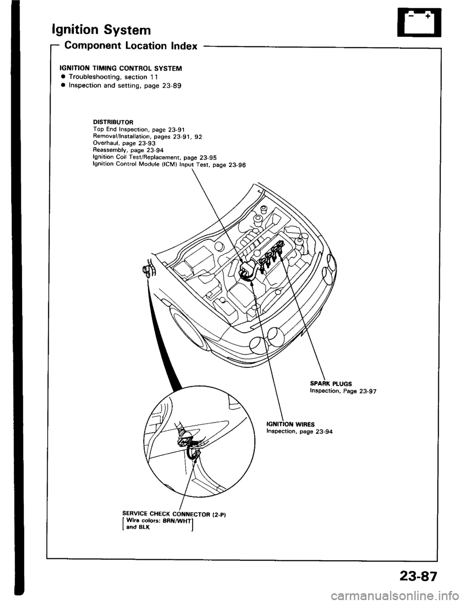
Gomponent Location Index
IGNITION TIMING CONTROL SYSTEMa Troubleshooting, section I1a Inspection and setting, page 23-89
DISTRIBUTORTop End Inspection, page 23-91Removal/lnstallation, pages 23-91, 92Overhaul, page 23-93Reassemblv, page 23,94lgnition Coil Test/Replacement, page 23-95lgnition Control Module {lCM} Inpur Test, page 23-96
WIRESInspection, psge 23-94
SPARK PLUGSfnspection, Page 23-97
23-87
Page 1196 of 1413
lgnition System
lgnition Timing lnspection and
Setting (cont'd)
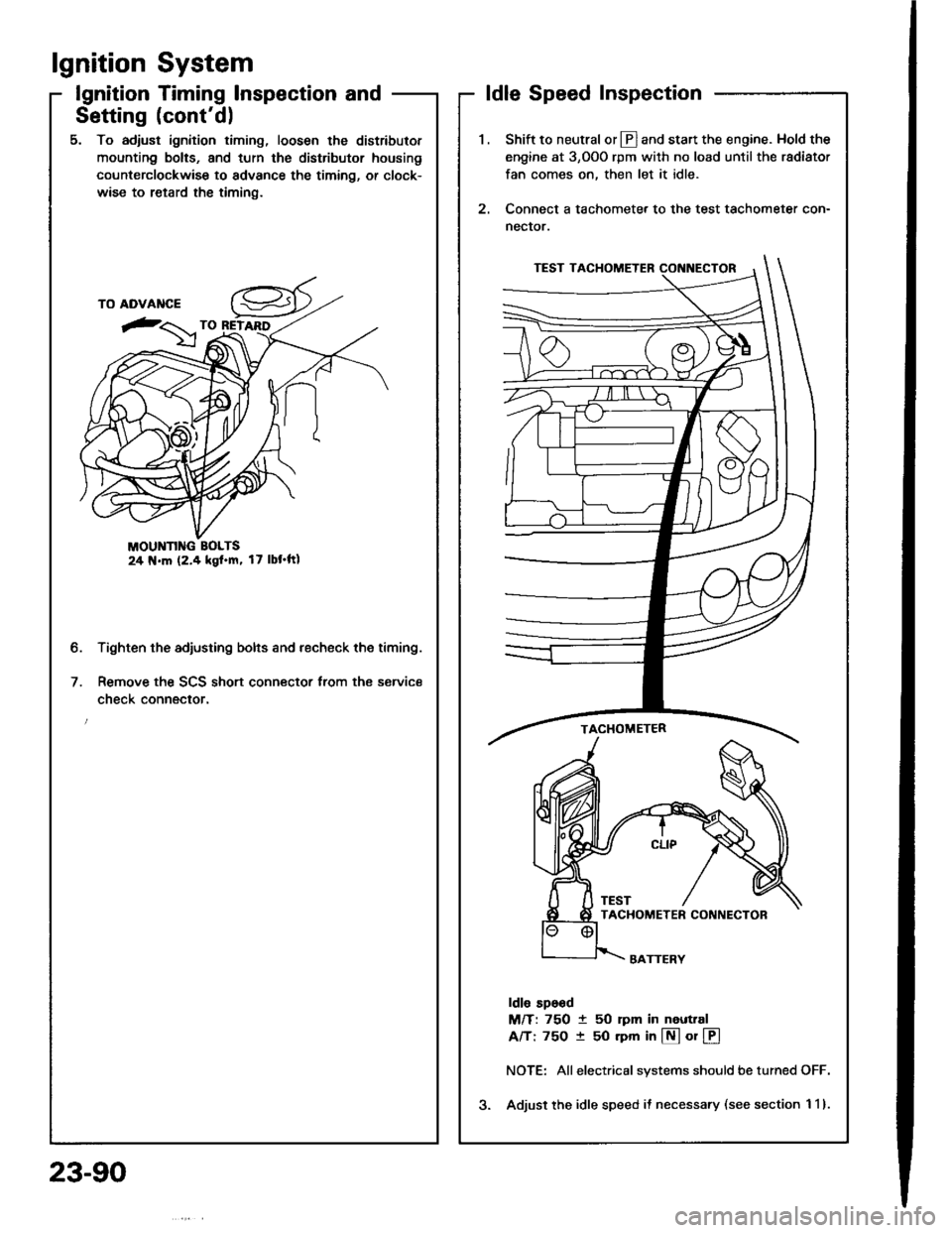
5. To adjust ignition timing, loosen the distributor
mounting bolts, and turn the distributor housing
counterclockwise to advance the timing, or clock-
wise to retard the timing.
MOUNN G BOLTS24 N.m (2.4 kgl.m, 17 lbt'ftl
Tighten the adjusting bolts and recheck the timing.
Remove the SCS short connector trom the service
check connector.
2.
ldle Speed Inspection
Shift to neutral or Ll] and start the engine. Hold the
engine at 3,OOO rpm with no load until the radiator
fan comes on, then let it idle.
Connect a tachometer to the test tachometer con-
nector.
ldle sp6od
M/T: 750 t 50 rpm in neuttal
A/T: 75O t 50 rpm in @ or @
NOTE: Allelectrical systems should be turned OFF.
Adjust the idle speed il necessary (see section 1 1).
b.
23-90
Page 1197 of 1413
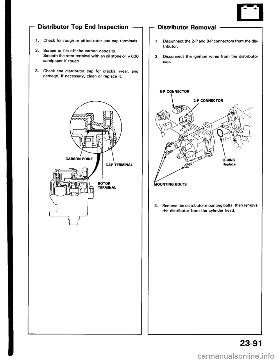
Distributor Top End Inspection
1.
2.
Check for rough or pitted rotor and cap tefminals.
Scrape or file oft the carbon deposits.
Smooth the rotor terminal with an oil stone or #600sandpaper i{ rough.
Check the distributor cap Jor cracks, wear, and
dSmage, lf necessary, clean or replace it.
2
Distributor Removal
1.
2.
Disconnect the 2-P and 8-P connectors from the dis-
tributor.
Disconnect the ignition wires from the distributor
cap.
3. Remove the distributor mounting bolts, then remove
the distributor Irom the cvlinder head.
23-91