driveshaft HONDA INTEGRA 1994 4.G Workshop Manual
[x] Cancel search | Manufacturer: HONDA, Model Year: 1994, Model line: INTEGRA, Model: HONDA INTEGRA 1994 4.GPages: 1413, PDF Size: 37.94 MB
Page 31 of 1413
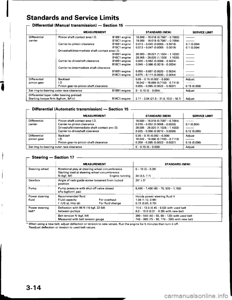
Standards and Service Limits
Differential (Manual transmissionlSection 15
Differential (Automatic transmissionlSection 15
Steering - Section 17
' When using a new belt, adjust detlection or tension to new values. Run the engine lor 5 minutes then turn it off.Readiust detlection or tension to used belt values.
M€ASUREMENTSTANDARD INEW) SERVICE LIMIT
DifferentialPinion shaft contact area LD. 81881 engine818C1 engineCarrier'to-pinion clearance 81881 engineB18C t engineDriveshafvintermediate shaft contact area LD.81881 engine818C1 engineCarrier to driveshaft clearance 81881 engineBlSC'l engineCarrier-to-intermediate shatt clearanceB188l engine818C1 engine
18.000 - 18.016 (0.7087 - 0.7093)18.000 18.018 (0.7087 - 0.7094)0.0r3 0.045 (0.0005 - 0.0018)0.0'13 - 0.047 (0.0005 0.0019)
28.000 - 28.021 \1.1024-1.1032128.005 - 28.025 (1.1026 1.'1033)0.020 - 0.062 (0.0008 0.0024)0.045 , 0.086 {0.0018 - 0.0034)
0.050 - 0.087 (0.0020 0.0034)0.075 - 0.111 (0.0030 - 0.0044)
o. t aron,0.1 {0.006}
Differentialprnron gearEacklasht. D.Pinion geaFto-pinion shaft clearance
0.05 0.15 (0.002 0.006)'18.042 - 18.066 (0.7103 0.7113)0.055 - 0.095 (0.0022 0.0037)
Adjust
0.15 {0.006)
Sel ring-to-bearing outer race clearance 81881 engin€0 - 0.10 (0 0.004)Adjust
Differential taper roller bearing preloadStarting torque N.m {kgfcm, lbf.in) Bl8Cl engine2.1r - 3.04 {21.5 - 3 r.0, 13.0- 18.7)Adjust
MEASUREMENTSTANDARO INEWISERVICE LIM]T
Difterentialcarfl€rPinion shatt contact area l.D.Carrier-to-oinion clearanceDriveshafvintermediate shaft contact are l.D.Carrier-to-driveshatt clearance
18.000 - 18.018 {0.7087 - 0.7094)0.016 - 0.052 {0.0006 - 0.0020)28.00s 28.025 {1.1026 - 1.1033)0.025 - 0.066 (0.0010 - 0.0026)
0.1 {0.004)
0.12 (0.005)
Differentialprnron gearBacklasht.D.Pinion gear-to-pinion shaft clearance
0.05 - 0.15 (0.002 - 0.006)18.042 - 18.066 (0.7r03 - 0.7113)0.059 - 0.095 (0.0023 - 0.0037)
Adjust
0.15 (0.006)
Set ring-to-bearing outer race clearance0 - 0.r5 (0 - 0.006)Adjust
MEASUREMENTSTANDARD INEWI
Steering wheelRotational play at steering wheel circumferenceStaning losd at steering wheel circumferenceN {kgf, lbfl Engine running
0 - 10 {0 - 0.39)
34 \3.5,7.71
GearboxAngle of rack-guide-screw loosened from lockedposition20" i 5'
PurnpPump pressure with shut-off valve closedkPa (kgtlcm,, psi)6,400 7.400 165 75. 920 - 1. r00)
Power steeringtluidRecommended fluidFluid capacity For overhaulf (US qt, lmp q0 For fluid change
Honda power steering fluid V1.06 (1.12,0.98)
0.79 (0.83,0.70)
Power steeringbelt*Deflection with 98 N (1okgt,22lhfl
between pulleys11.5- 13.5 (0.45 0.53)with used belt8.0 - 10.010.31 0.39)with new belt
Belt tension N lkgf, lbl)Measured with belt tension gauge390 - 540 (40 - 55, 88 - 120) with used belt740 880175 90. 170 200) with new belt
Page 54 of 1413
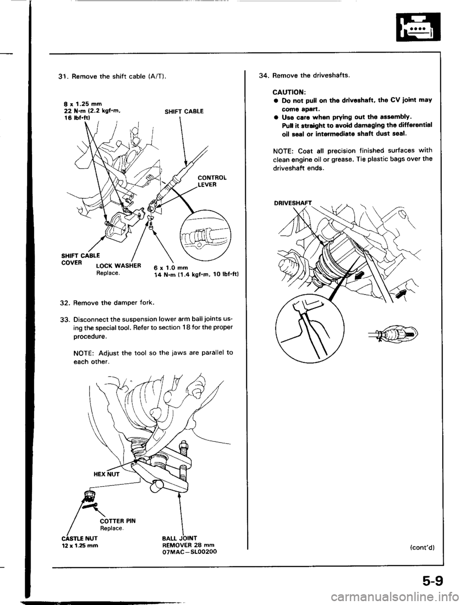
31. Remove the shift cable
I x 1.25 mm22 f.m 12.2 kgl'rn'16 tbl.ftl
(A/T).
SHIFT CABLE
32.
33.
CONTROLLEVER
SHIFT CAALEcovER locx usiea6 x 1.0 mm14 N.m t1.4 kgf.m, 10 lbl'ftlReplace.
Remove the damper tork.
Disconnect the suspension lower arm balljoints us-
ing the special tool. Refer to section 1 8 tor the proper
procedure.
NOTE: Adjust the tool so the iaws are parallel to
each other.
REMOVER 28 mmoTMAC-S10020012 x 1.25 mm
5-9
34. Remove the driveshatls.
CAUTION:
a Do not pull on tho ddv$halt, tho CV ioint mav
como apan.
a Uso caro whsn prying out tho assombly.
Pult it slraight to avoid damaging th6 differantial
oil soal or intormodiato shaft dust seal.
NOTE: Coat all precision tinished surfaces with
clean engine oil or grease. Tie plastic bags over the
driveshaft ends.
(cont'd)
Page 60 of 1413
![HONDA INTEGRA 1994 4.G Workshop Manual Insrall the left front mount, then tighten the bolts in
the numbered sequence as shown (O-@),
O 12 x 1.25 ]n]n83 N.m 18.5 kst.m,61 lbt.ftlReplace.
@ 12 r 1.25 mm59 N.m {6.0 kgl.n,43 tb{.ftlReplace.
@ HONDA INTEGRA 1994 4.G Workshop Manual Insrall the left front mount, then tighten the bolts in
the numbered sequence as shown (O-@),
O 12 x 1.25 ]n]n83 N.m 18.5 kst.m,61 lbt.ftlReplace.
@ 12 r 1.25 mm59 N.m {6.0 kgl.n,43 tb{.ftlReplace.
@](/img/13/6067/w960_6067-59.png)
Insrall the left front mount, then tighten the bolts in
the numbered sequence as shown (O-@),
O 12 x 1.25 ]n]n83 N.m 18.5 kst.m,61 lbt.ftlReplace.
@ 12 r 1.25 mm59 N.m {6.0 kgl.n,43 tb{.ftlReplace.
@ 10 r 1.25 mm44 N.m (4.5 kgf.m, 33 lbt.ftl
k-
5-15
a Check that the sp.ing clip on the end of each
driveshaft clicks into place.
GAUTION: Uso oow spring clips.
a Bleed air trom the cooling system at the bleed bolt
with the heater valve open (see page 10-5).
a Adjust the th.ottle cable (see section 1 1).
a Check the clutch pedal tree play lsee section 12).
a Check that the transmission shifts into gear
smoothlv,
a Adiust the tension of the following drive belts.
Alternator belt {s€e section 23).
P/S pump belt {see section 17).
A/C comoressor belt (see section 22).
a Inspect tor fuel leakage (see section 1 1).
. After assembling fuel line parts, turn on the ig-
nition switch (do not operate th€ starter) so
that the Juel pump operates for approximat€-
lV two seconds and the tuel line pressurizes.
Repeat this operation two or three times and
check for fuel leakage at any point in the fuel
line.
(cont'd)
Page 330 of 1413
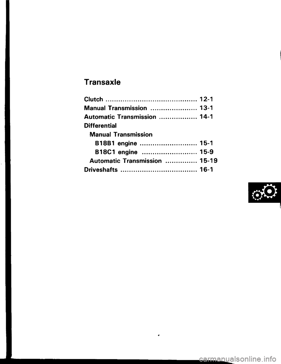
Transaxle
Clutch
Manual Transmission ......................
Automatic Transmission ..................
Differential
Manual Transmission
81881 engine
818C1 engine
Automatic Transmission ...............
Driveshafts
12-1
13-1
14-1
15-1
15-9
15-19
16-1
Page 390 of 1413
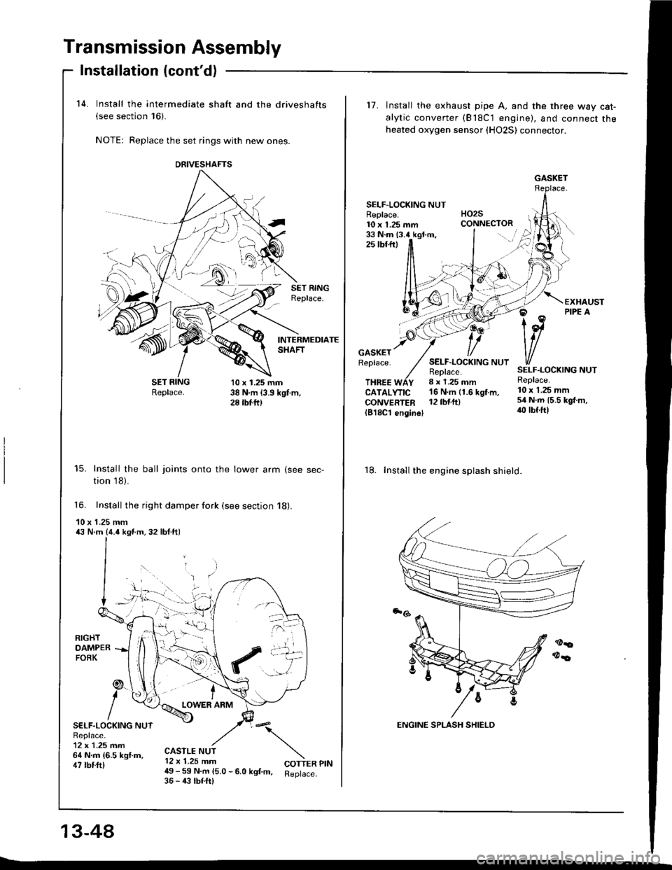
Transmission Assembly
14. Install the intermediate shaft and the driveshafts(see section 16)-
NOTE: Replace the set rings with new ones.
Installation (cont'd)
-Sl
SET RINGReplace.
INTERMEDIATESHAFT
Replace.10 x 1.25 mm38 N.m (3.9 kgt m,28 tbtft)
15. Install the ball joints onto the lower arm (see sec-
tion 18).
16. Install the right damper fork (see section 18).
10 x 1.25 mm43 N.m {4.o ksf.m.32 lbf.ft)
RIGHTDAMPERFOBK
SELF.LOCKING NUTReplace.12 x 1.25 mm64 N.m {6.5 kgf.m,47 tbtft)
tLOWER ARM
:\
COTTER PIN
CASTLE NUT12 x 1.25 mm49 - 59 N.m 15.0 - 6.0 kgf m. Reptace.36 - 43 tbf.frl
13-44
DNIVESHAFTS
::.t
L
17. lnstall the exhaust pipe A, and the three way cat-
alytic converter (Bl8C'1 engine), and connect theheated oxygen sensor (HO2S) connector.
SELF-LOCKING NUTHO2SCONNECTORReplace.10 x 1.25 mm33 N.m (3.4 kgt.m,2s tbtftt
GASKETReplace.SELF.LOCKING NUTReplace.8 x 1.25 mm
SELF.LOCKING NUTReplace.THREE WAYCATALYTICCONVERTER1818C'l enginel
16 N'm 11.6 kgt m, 10 x 1 25 mm
l2tbt.ftl 54 N.m 15.5 kgt m,iro lbf.ftl
18. Install the engine splash shield.
GASKET
Page 493 of 1413
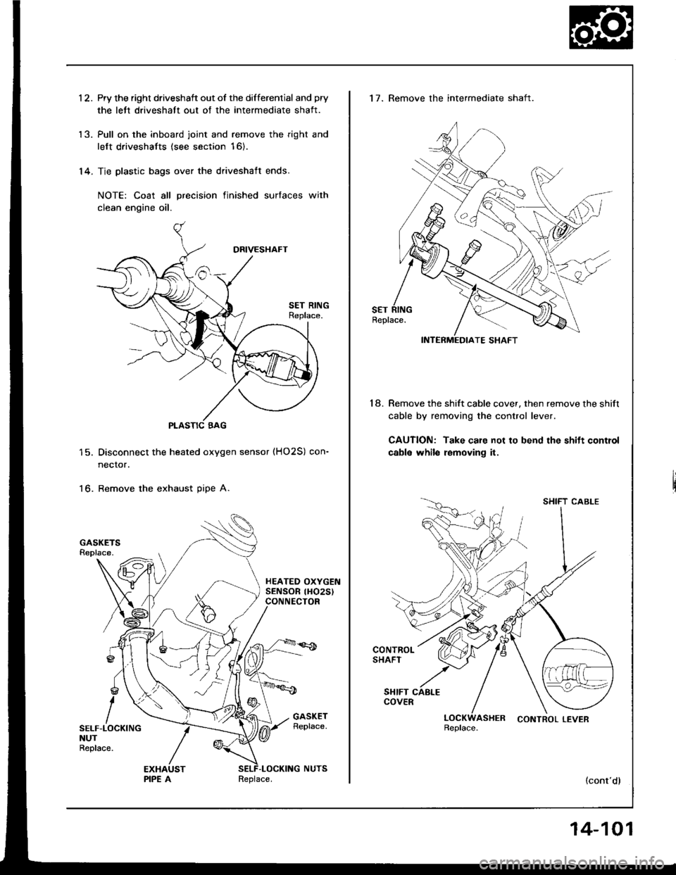
1 2. Pry the right driveshaft out of the differential and pry
the lett driveshatt out of the intermediate shaft.
'13. Pull on the inboard joint and remove the right and
left driveshafts (see section 16).
'14. Tie plastic bags over the driveshaft ends.
NOTE: Coat all precision finished surfaces with
clean engine oil.
PLASTIC BAG
Disconnect the heated oxygen sensor (HO2S) con-
necror.
Remove the exhaust pipe A.16.
SELF-LOCKINGNUTReplace.
Replace.
14-101
17. Remove the intermediate shaft.
Remove the shift cable cover, then remove the shift
cable by removing the control lever.
CAUTION: Take care not to bend the shift control
cabls whilo removing it.
18.
SHIFT CABLE
LOCKWASHER CONTROLLEVERReplace.
(cont'dl
Page 556 of 1413
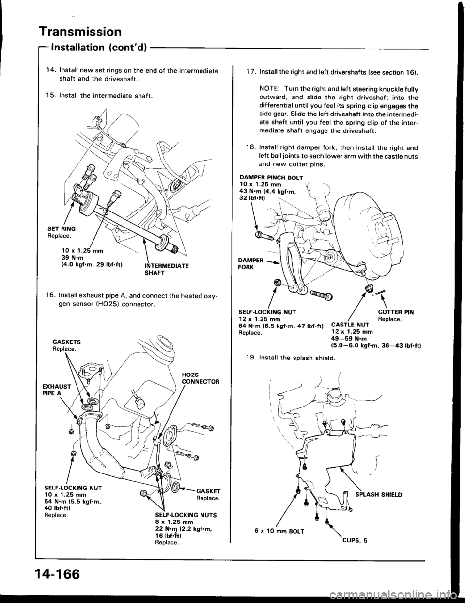
Transmission
Installation {cont'd)
14.
15.
Install new set rings on the end of the intermediate
shaft and the driveshaft.
Install the intermediate shaft.
SET RINGBeplace.
16.
10 x 139 N.m14.O kgf.m, 29 lbf.ftl
Install exhaust pipe A. and connect the heated oxv-gen sensor {HO2S) connector.
SELF-LOCKING NUT10 x 1.25 mm54 N.m (5.5 kgl.m,40 rbt.trlReplace.
GASKETReplace.
SELF.LOCKING NUTSI x 1.25 mm22 N.m 12.2 kgl'n,16 lbt.trlRepl6ce.
SHAFT
14-166
DAMPER PINCH BOLT10 x 1.25 mm43 N.m 14.4 kgf.m,32 tbr.ftl
1 7. Install the right and left drivershafts (see section l6l.
NOTE: Turn the right and left steering knuckle fullyoutward, and slide the right driveshaft into the
differential until you feel its spring clip engages theside geaf. Slide the left driveshaft into the intermedi-
ate shaft until you teel the spring clip of the inter-mediate shaft engage the driveshaft.
18. Install right damper fork, then install the right andlett balljoints to each lower arm with the castle nuts
and new cotter Dins.
\
COTTERReplace.CASTLE NUT12 x 1.25 mm49-59 N.m{5.O-6.0 ksf.m, 36-43
SELF.LOCKING NUT12 x 1 .25 mm64 N.m (6.5 kgl.h, 47 lbt.ftlReplace.
rbt'ft1
19. Install the splash shield.
6 x 10 mm BOLT
cltPs, 5
Page 595 of 1413
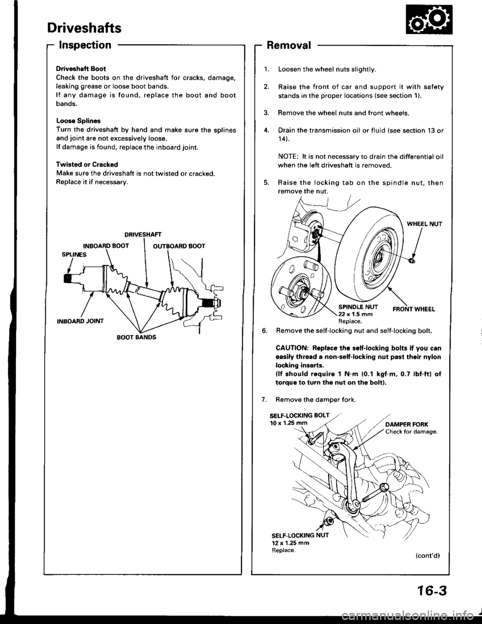
Driveshafts
Inspection
Driveshaft Boot
Check the boots on the driveshaft for cracks,
leaking grease or loose boot bands.
lf any damage is found, replace the boot
Danos.
Looso Splines
Turn the driveshaft by hand and make sure the splines
and joint are not excessivelV loose.
lf damage is found, replace the inboard joint,
Twistod or Cracked
Make sure the driveshaft is not twisted or cracked.
Replace it if necessarv.
damage,
and boot
Removal
Loosen the wheel nuts slightly.
Raise the front of car and support it with safety
stands in the proper locataons (see section 1),
Remove the wheel nuts and front wheels,
Drain the transmission oil or fluid (see section 13 or
14).
NOTE: lt is not necessary to drain the differential oil
when the left driveshaft is removed.
Raise the locking tab on the spindle nut, then
remove the nut.
WHEEL NUT
6. Remove the self-locking nut and self-locking bolt.
GAUTION: Roplaco th€ s€lt.locking bolts if you can
sasily thread a non€elf-locking nut prst thoir nylon
locking inserts.(lf should require I N.m (0.1 kgt.m, 0.7 lbf.ft) ol
torqus to turn lhs nut on the bolt).
Remove the damDer fork.
SELF.LOCKING BOLT
10 x 1.25 mm
SELF-LOCKING NUT
12 x 1.25 mmReplace.(cont'dl
DBIVESTIAFT
EOOT BANDS
Replace.
16-3
Page 596 of 1413
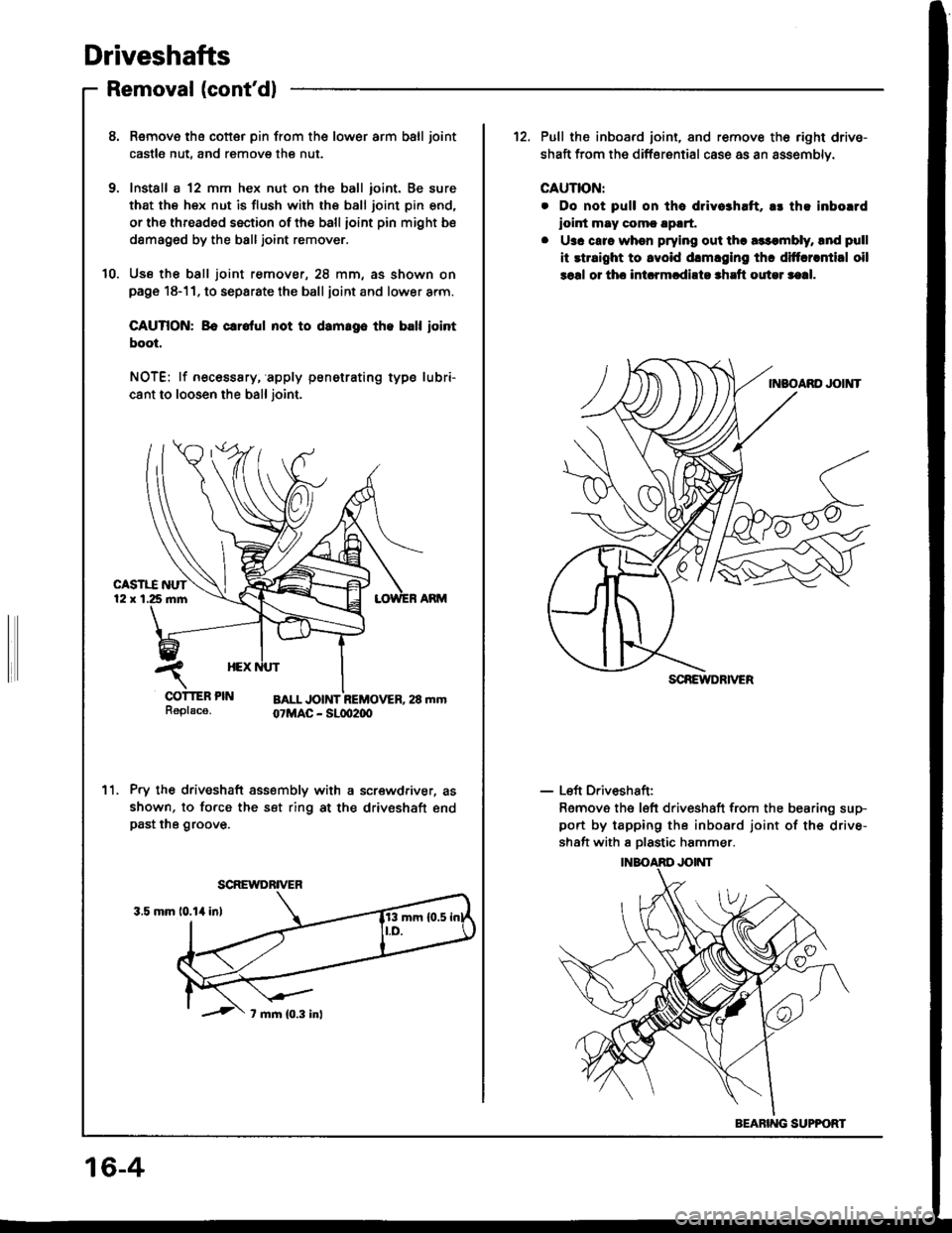
Driveshafts
Removal (cont'dl
8. Remove tha cotter pin from the lower arm ball joint
castle nut, and remove the nut.
9. Install a 12 mm hex nut on the ball ioint. Be sure
that the hex nut is flush with the ball joint pin end,
or the threaded section of the ball ioint pin might be
damag6d by the balljoint remover.
10. Use th€ ball joint remover, 28 mm, as shown onpage 18-11. to separate the ball joint and lower arm.
CAUTION: Bo crrolul not to damrgo th. ball iointboot.
NOTE: lf necesssry, apply penetrating type lubri-
cant to loosen the ball joint.
Pry the driveshaft assembly with a screwdriver, as
shown, to force the set ring at the driveshaft endpast the groove.
11.
SCREWDRIVER
12. Pull the inboard joint, and remove th6 right drive-
shaft from the differential case as an assemblv.
CAUTION:
. Do not pull on tha dlivo3haft, a! th! inborrd
ioint may comc !p!rt,
. U3c carc when prying out tha a$qnbly, lnd pull
it rtraight to lvoid drmlging thc diftcrrntial oil
soal or thc int.rmcdirto shrft outel saal.
- Left Driveshaft:
Remove the left driveshaft from the bearing sup-
port by tapping the inboard joint of the drive-
shaft with I Dlastic hammer.
SCREIYDRIVER
BEARING SUPPOFT
16-4
Page 597 of 1413
KNUCKLE
DRIVESHAFT
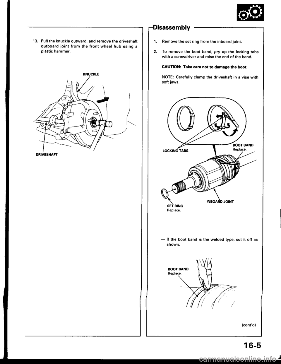
13. Pull the knuckle outward, and remove the driveshaft
outboard joint from the front wheel hub using I
Dlastic hammer.
Remove the set ring from the inboard joint.
To remove the boot band, pry up the locking tabs
with a screwdriver and raise the end of the band,
CAUTION: Taks caro not to damagc thc boot.
NOTE: Carefully clamp the driveshaft in a vise with
soft iaws.
SET RINGReplace.
- lf the boot band is the welded type, cut it off as
snown,
1.
16-5